1995 JEEP YJ service
[x] Cancel search: servicePage 1678 of 2158
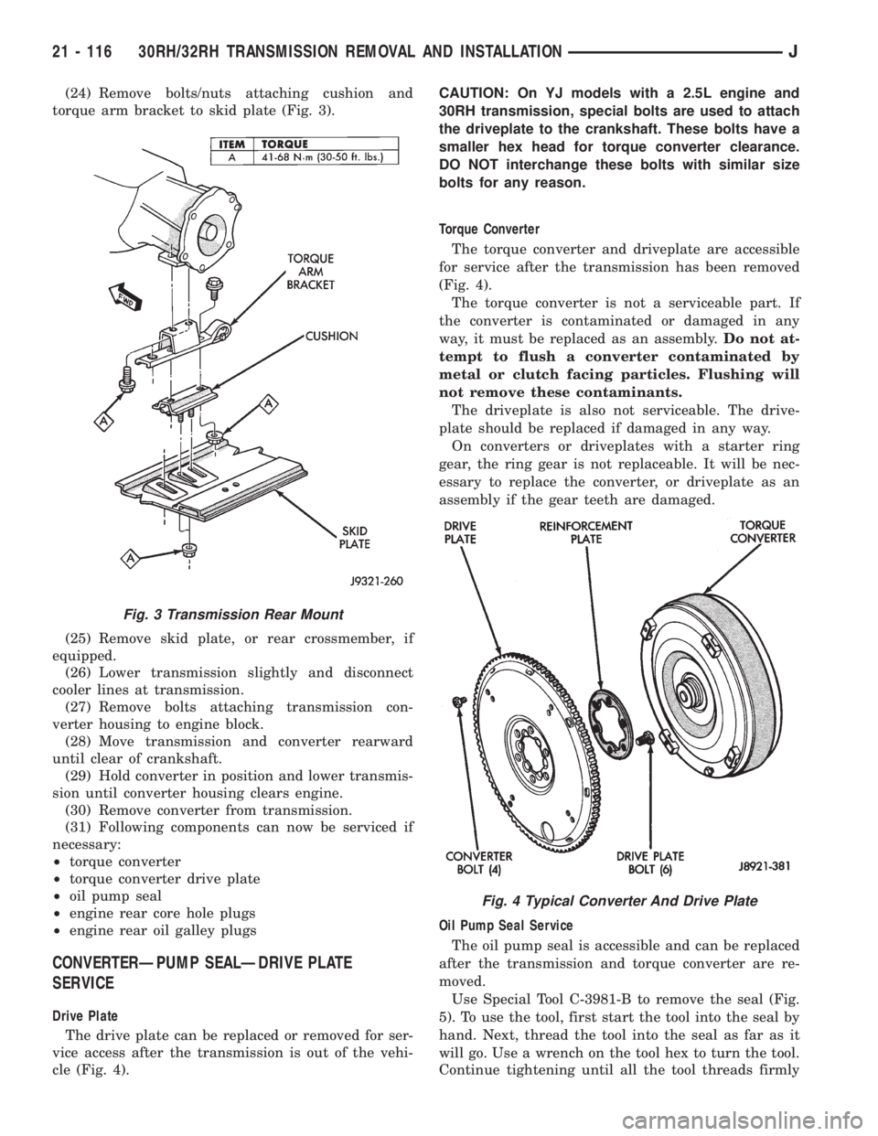
(24) Remove bolts/nuts attaching cushion and
torque arm bracket to skid plate (Fig. 3).
(25) Remove skid plate, or rear crossmember, if
equipped.
(26) Lower transmission slightly and disconnect
cooler lines at transmission.
(27) Remove bolts attaching transmission con-
verter housing to engine block.
(28) Move transmission and converter rearward
until clear of crankshaft.
(29) Hold converter in position and lower transmis-
sion until converter housing clears engine.
(30) Remove converter from transmission.
(31) Following components can now be serviced if
necessary:
²torque converter
²torque converter drive plate
²oil pump seal
²engine rear core hole plugs
²engine rear oil galley plugs
CONVERTERÐPUMP SEALÐDRIVE PLATE
SERVICE
Drive Plate
The drive plate can be replaced or removed for ser-
vice access after the transmission is out of the vehi-
cle (Fig. 4).CAUTION: On YJ models with a 2.5L engine and
30RH transmission, special bolts are used to attach
the driveplate to the crankshaft. These bolts have a
smaller hex head for torque converter clearance.
DO NOT interchange these bolts with similar size
bolts for any reason.
Torque Converter
The torque converter and driveplate are accessible
for service after the transmission has been removed
(Fig. 4).
The torque converter is not a serviceable part. If
the converter is contaminated or damaged in any
way, it must be replaced as an assembly.Do not at-
tempt to flush a converter contaminated by
metal or clutch facing particles. Flushing will
not remove these contaminants.
The driveplate is also not serviceable. The drive-
plate should be replaced if damaged in any way.
On converters or driveplates with a starter ring
gear, the ring gear is not replaceable. It will be nec-
essary to replace the converter, or driveplate as an
assembly if the gear teeth are damaged.
Oil Pump Seal Service
The oil pump seal is accessible and can be replaced
after the transmission and torque converter are re-
moved.
Use Special Tool C-3981-B to remove the seal (Fig.
5). To use the tool, first start the tool into the seal by
hand. Next, thread the tool into the seal as far as it
will go. Use a wrench on the tool hex to turn the tool.
Continue tightening until all the tool threads firmly
Fig. 3 Transmission Rear Mount
Fig. 4 Typical Converter And Drive Plate
21 - 116 30RH/32RH TRANSMISSION REMOVAL AND INSTALLATIONJ
Page 1681 of 2158
30RH/32RH TRANSMISSION OVERHAUL
INDEX
page page
Adapter/Extension Housing Inspection and Park
Lock Component Overhaul................ 127
Front Clutch Overhaul..................... 134
Front Servo and Band Overhaul............. 146
Governor and Park Gear Overhaul........... 127
Oil Pump Overhaul....................... 131
Overhaul Service Information................ 125
Overrunning ClutchÐLow-Reverse DrumÐRear
Support Overhaul....................... 125
Planetary Gear Train Overhaul.............. 141Rear Clutch Overhaul..................... 138
Rear Servo and Band Overhaul.............. 146
Transmission Assembly and Adjustment Procedures. 155
Transmission Assembly Tips................ 155
Transmission Case Cleaning and Inspection.... 125
Transmission Disassembly.................. 119
Valve Body Assembly and Adjustment......... 153
Valve Body Disassembly and Inspection....... 147
TRANSMISSION DISASSEMBLY
(1) Clean transmission exterior with steam gun or
with solvent. Wear eye protection during cleaning
process.
(2) Remove throttle and shift levers from valve
body manual shaft and throttle lever shaft.
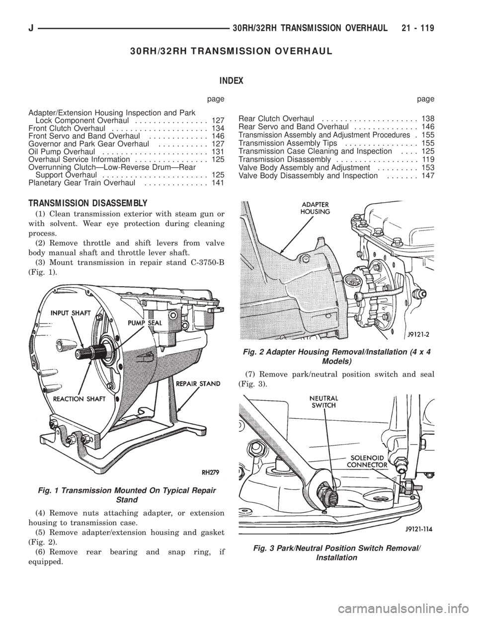
(3) Mount transmission in repair stand C-3750-B
(Fig. 1).
(4) Remove nuts attaching adapter, or extension
housing to transmission case.
(5) Remove adapter/extension housing and gasket
(Fig. 2).
(6) Remove rear bearing and snap ring, if
equipped.(7) Remove park/neutral position switch and seal
(Fig. 3).
Fig. 1 Transmission Mounted On Typical Repair
Stand
Fig. 2 Adapter Housing Removal/Installation (4 x 4
Models)
Fig. 3 Park/Neutral Position Switch Removal/
Installation
J30RH/32RH TRANSMISSION OVERHAUL 21 - 119
Page 1687 of 2158
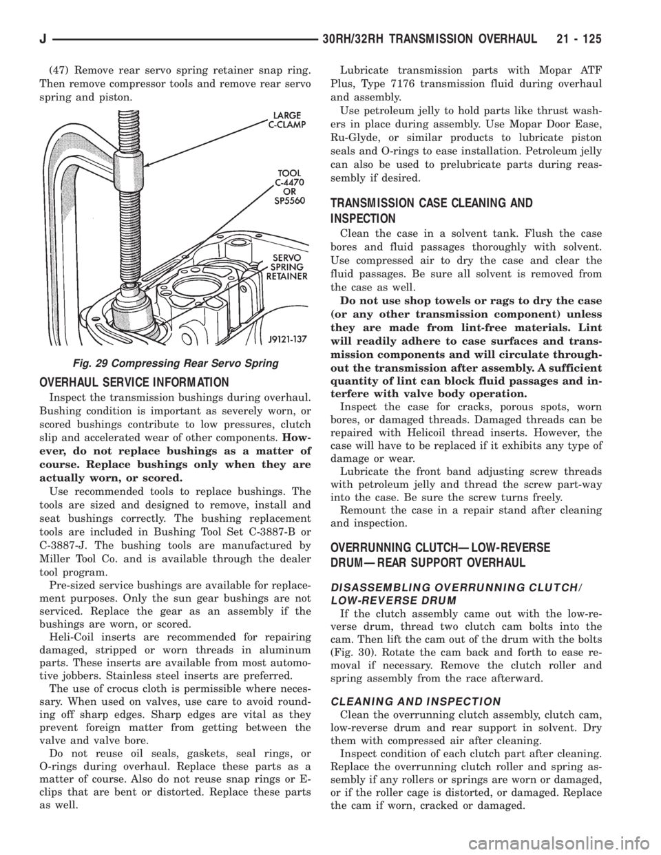
(47) Remove rear servo spring retainer snap ring.
Then remove compressor tools and remove rear servo
spring and piston.
OVERHAUL SERVICE INFORMATION
Inspect the transmission bushings during overhaul.
Bushing condition is important as severely worn, or
scored bushings contribute to low pressures, clutch
slip and accelerated wear of other components.How-
ever, do not replace bushings as a matter of
course. Replace bushings only when they are
actually worn, or scored.
Use recommended tools to replace bushings. The
tools are sized and designed to remove, install and
seat bushings correctly. The bushing replacement
tools are included in Bushing Tool Set C-3887-B or
C-3887-J. The bushing tools are manufactured by
Miller Tool Co. and is available through the dealer
tool program.
Pre-sized service bushings are available for replace-
ment purposes. Only the sun gear bushings are not
serviced. Replace the gear as an assembly if the
bushings are worn, or scored.
Heli-Coil inserts are recommended for repairing
damaged, stripped or worn threads in aluminum
parts. These inserts are available from most automo-
tive jobbers. Stainless steel inserts are preferred.
The use of crocus cloth is permissible where neces-
sary. When used on valves, use care to avoid round-
ing off sharp edges. Sharp edges are vital as they
prevent foreign matter from getting between the
valve and valve bore.
Do not reuse oil seals, gaskets, seal rings, or
O-rings during overhaul. Replace these parts as a
matter of course. Also do not reuse snap rings or E-
clips that are bent or distorted. Replace these parts
as well.Lubricate transmission parts with Mopar ATF
Plus, Type 7176 transmission fluid during overhaul
and assembly.
Use petroleum jelly to hold parts like thrust wash-
ers in place during assembly. Use Mopar Door Ease,
Ru-Glyde, or similar products to lubricate piston
seals and O-rings to ease installation. Petroleum jelly
can also be used to prelubricate parts during reas-
sembly if desired.
TRANSMISSION CASE CLEANING AND
INSPECTION
Clean the case in a solvent tank. Flush the case
bores and fluid passages thoroughly with solvent.
Use compressed air to dry the case and clear the
fluid passages. Be sure all solvent is removed from
the case as well.
Do not use shop towels or rags to dry the case
(or any other transmission component) unless
they are made from lint-free materials. Lint
will readily adhere to case surfaces and trans-
mission components and will circulate through-
out the transmission after assembly. A sufficient
quantity of lint can block fluid passages and in-
terfere with valve body operation.
Inspect the case for cracks, porous spots, worn
bores, or damaged threads. Damaged threads can be
repaired with Helicoil thread inserts. However, the
case will have to be replaced if it exhibits any type of
damage or wear.
Lubricate the front band adjusting screw threads
with petroleum jelly and thread the screw part-way
into the case. Be sure the screw turns freely.
Remount the case in a repair stand after cleaning
and inspection.
OVERRUNNING CLUTCHÐLOW-REVERSE
DRUMÐREAR SUPPORT OVERHAUL
DISASSEMBLING OVERRUNNING CLUTCH/
LOW-REVERSE DRUM
If the clutch assembly came out with the low-re-
verse drum, thread two clutch cam bolts into the
cam. Then lift the cam out of the drum with the bolts
(Fig. 30). Rotate the cam back and forth to ease re-
moval if necessary. Remove the clutch roller and
spring assembly from the race afterward.
CLEANING AND INSPECTION
Clean the overrunning clutch assembly, clutch cam,
low-reverse drum and rear support in solvent. Dry
them with compressed air after cleaning.
Inspect condition of each clutch part after cleaning.
Replace the overrunning clutch roller and spring as-
sembly if any rollers or springs are worn or damaged,
or if the roller cage is distorted, or damaged. Replace
the cam if worn, cracked or damaged.
Fig. 29 Compressing Rear Servo Spring
J30RH/32RH TRANSMISSION OVERHAUL 21 - 125
Page 1698 of 2158
Replace the clutch discs if warped, worn, scored,
burned or charred, or if the facing is flaking off. Re-
place the steel plates if heavily scored, warped, or
broken. Be sure the driving lugs on the plates are in
good condition. The lugs must not be bent, cracked or
damaged in any way.
Replace the clutch spring and spring retainer if ei-
ther is distorted, warped or broken.
Check the lug grooves in the clutch retainer. The
steel plates should slide freely in the slots. Replace
the retainer if the grooves are worn or damaged.
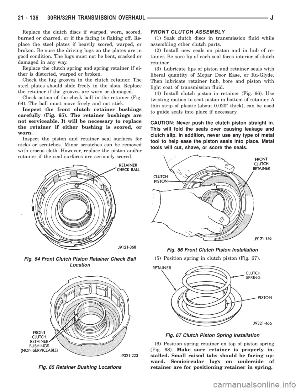
Check action of the check ball in the retainer (Fig.
64). The ball must move freely and not stick.
Inspect the front clutch retainer bushings
carefully (Fig. 65). The retainer bushings are
not serviceable. It will be necessary to replace
the retainer if either bushing is scored, or
worn.
Inspect the piston and retainer seal surfaces for
nicks or scratches. Minor scratches can be removed
with crocus cloth. However, replace the piston and/or
retainer if the seal surfaces are seriously scored.FRONT CLUTCH ASSEMBLY
(1) Soak clutch discs in transmission fluid while
assembling other clutch parts.
(2) Install new seals on piston and in hub of re-
tainer. Be sure lip of each seal faces interior of clutch
retainer.
(3) Lubricate lips of piston and retainer seals with
liberal quantity of Mopar Door Ease, or Ru-Glyde.
Then lubricate retainer hub, bore and piston with
light coat of transmission fluid.
(4) Install clutch piston in retainer (Fig. 66). Use
twisting motion to seat piston in bottom of retainer. A
thin strip of plastic (about 0.0209thick), can be used
to guide seals into place if necessary.
CAUTION: Never push the clutch piston straight in.
This will fold the seals over causing leakage and
clutch slip. In addition, never use any type of metal
tool to help ease the piston seals into place. Metal
tools will cut, shave, or score the seals.
(5) Position spring in clutch piston (Fig. 67).
(6) Position spring retainer on top of piston spring
(Fig. 68).Make sure retainer is properly in-
stalled. Small raised tabs should be facing up-
ward. Semicircular lugs on underside of
retainer are for positioning retainer in spring.
Fig. 64 Front Clutch Piston Retainer Check Ball
Location
Fig. 65 Retainer Bushing Locations
Fig. 66 Front Clutch Piston Installation
Fig. 67 Clutch Piston Spring Installation
21 - 136 30RH/32RH TRANSMISSION OVERHAULJ
Page 1703 of 2158
PLANETARY GEAR TRAIN OVERHAUL
PLANETARY GEARTRAIN DISASSEMBLY
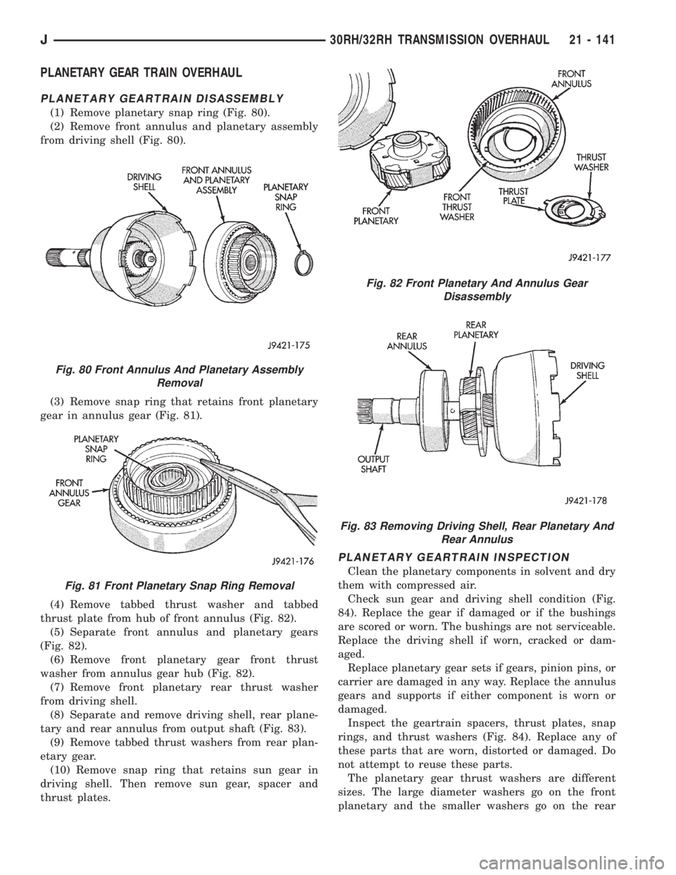
(1) Remove planetary snap ring (Fig. 80).
(2) Remove front annulus and planetary assembly
from driving shell (Fig. 80).
(3) Remove snap ring that retains front planetary
gear in annulus gear (Fig. 81).
(4) Remove tabbed thrust washer and tabbed
thrust plate from hub of front annulus (Fig. 82).
(5) Separate front annulus and planetary gears
(Fig. 82).
(6) Remove front planetary gear front thrust
washer from annulus gear hub (Fig. 82).
(7) Remove front planetary rear thrust washer
from driving shell.
(8) Separate and remove driving shell, rear plane-
tary and rear annulus from output shaft (Fig. 83).
(9) Remove tabbed thrust washers from rear plan-
etary gear.
(10) Remove snap ring that retains sun gear in
driving shell. Then remove sun gear, spacer and
thrust plates.
PLANETARY GEARTRAIN INSPECTION
Clean the planetary components in solvent and dry
them with compressed air.
Check sun gear and driving shell condition (Fig.
84). Replace the gear if damaged or if the bushings
are scored or worn. The bushings are not serviceable.
Replace the driving shell if worn, cracked or dam-
aged.
Replace planetary gear sets if gears, pinion pins, or
carrier are damaged in any way. Replace the annulus
gears and supports if either component is worn or
damaged.
Inspect the geartrain spacers, thrust plates, snap
rings, and thrust washers (Fig. 84). Replace any of
these parts that are worn, distorted or damaged. Do
not attempt to reuse these parts.
The planetary gear thrust washers are different
sizes. The large diameter washers go on the front
planetary and the smaller washers go on the rear
Fig. 80 Front Annulus And Planetary Assembly
Removal
Fig. 81 Front Planetary Snap Ring Removal
Fig. 82 Front Planetary And Annulus Gear
Disassembly
Fig. 83 Removing Driving Shell, Rear Planetary And
Rear Annulus
J30RH/32RH TRANSMISSION OVERHAUL 21 - 141
Page 1712 of 2158
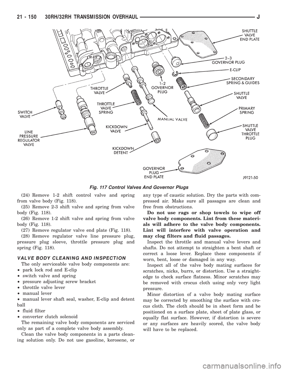
(24) Remove 1-2 shift control valve and spring
from valve body (Fig. 118).
(25) Remove 2-3 shift valve and spring from valve
body (Fig. 118).
(26) Remove 1-2 shift valve and spring from valve
body (Fig. 118).
(27) Remove regulator valve end plate (Fig. 118).
(28) Remove regulator valve line pressure plug,
pressure plug sleeve, throttle pressure plug and
spring (Fig. 118).
VALVE BODY CLEANING AND INSPECTION
The only serviceable valve body components are:
²park lock rod and E-clip
²switch valve and spring
²pressure adjusting screw bracket
²throttle valve lever
²manual lever
²manual lever shaft seal, washer, E-clip and detent
ball
²fluid filter
²converter clutch solenoid
The remaining valve body components are serviced
only as part of a complete valve body assembly.
Clean the valve body components in a parts clean-
ing solution only. Do not use gasoline, kerosene, orany type of caustic solution. Dry the parts with com-
pressed air. Make sure all passages are clean and
free from obstructions.
Do not use rags or shop towels to wipe off
valve body components. Lint from these materi-
als will adhere to the valve body components.
Lint will interfere with valve operation and
may clog filters and fluid passages.
Inspect the throttle and manual valve levers and
shafts. Do not attempt to straighten a bent shaft or
correct a loose lever. Replace these components if
worn, bent, loose or damaged in any way.
Inspect all of the valve body mating surfaces for
scratches, nicks, burrs, or distortion. Use a straight-
edge to check surface flatness. Minor scratches may
be removed with crocus cloth using only very light
pressure.
Minor distortion of a valve body mating surface
may be corrected by smoothing the surface with cro-
cus cloth. The cloth should be in sheet form and be
positioned on a surface plate, sheet of plate glass, or
equally flat surface. However, if distortion is severe
or any surfaces are heavily scored, the valve body
will have to be replaced.
Fig. 117 Control Valves And Governor Plugs
21 - 150 30RH/32RH TRANSMISSION OVERHAULJ
Page 1717 of 2158
justment must be performed properly and in the cor-
rect sequence. The correct sequence is line pressure
adjustment first and throttle pressure adjustment
last.
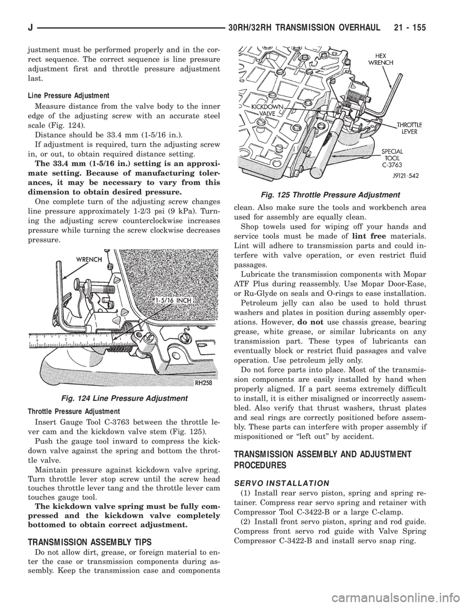
Line Pressure Adjustment
Measure distance from the valve body to the inner
edge of the adjusting screw with an accurate steel
scale (Fig. 124).
Distance should be 33.4 mm (1-5/16 in.).
If adjustment is required, turn the adjusting screw
in, or out, to obtain required distance setting.
The 33.4 mm (1-5/16 in.) setting is an approxi-
mate setting. Because of manufacturing toler-
ances, it may be necessary to vary from this
dimension to obtain desired pressure.
One complete turn of the adjusting screw changes
line pressure approximately 1-2/3 psi (9 kPa). Turn-
ing the adjusting screw counterclockwise increases
pressure while turning the screw clockwise decreases
pressure.
Throttle Pressure Adjustment
Insert Gauge Tool C-3763 between the throttle le-
ver cam and the kickdown valve stem (Fig. 125).
Push the gauge tool inward to compress the kick-
down valve against the spring and bottom the throt-
tle valve.
Maintain pressure against kickdown valve spring.
Turn throttle lever stop screw until the screw head
touches throttle lever tang and the throttle lever cam
touches gauge tool.
The kickdown valve spring must be fully com-
pressed and the kickdown valve completely
bottomed to obtain correct adjustment.
TRANSMISSION ASSEMBLY TIPS
Do not allow dirt, grease, or foreign material to en-
ter the case or transmission components during as-
sembly. Keep the transmission case and componentsclean. Also make sure the tools and workbench area
used for assembly are equally clean.
Shop towels used for wiping off your hands and
service tools must be made oflint freematerials.
Lint will adhere to transmission parts and could in-
terfere with valve operation, or even restrict fluid
passages.
Lubricate the transmission components with Mopar
ATF Plus during reassembly. Use Mopar Door-Ease,
or Ru-Glyde on seals and O-rings to ease installation.
Petroleum jelly can also be used to hold thrust
washers and plates in position during assembly oper-
ations. However,do notuse chassis grease, bearing
grease, white grease, or similar lubricants on any
transmission part. These types of lubricants can
eventually block or restrict fluid passages and valve
operation. Use petroleum jelly only.
Do not force parts into place. Most of the transmis-
sion components are easily installed by hand when
properly aligned. If a part seems extremely difficult
to install, it is either misaligned or incorrectly assem-
bled. Also verify that thrust washers, thrust plates
and seal rings are correctly positioned before assem-
bly. These parts can interfere with proper assembly if
mispositioned or ``left out'' by accident.
TRANSMISSION ASSEMBLY AND ADJUSTMENT
PROCEDURES
SERVO INSTALLATION
(1) Install rear servo piston, spring and spring re-
tainer. Compress rear servo spring and retainer with
Compressor Tool C-3422-B or a large C-clamp.
(2) Install front servo piston, spring and rod guide.
Compress front servo rod guide with Valve Spring
Compressor C-3422-B and install servo snap ring.
Fig. 124 Line Pressure Adjustment
Fig. 125 Throttle Pressure Adjustment
J30RH/32RH TRANSMISSION OVERHAUL 21 - 155
Page 1727 of 2158
AW-4 AUTOMATIC TRANSMISSION
CONTENTS
page page
AW-4 AUTOMATIC TRANSMISSION........ 165
AW-4 IN-VEHICLE SERVICE.............. 182
AW-4 TRANSMISSION DIAGNOSIS......... 176
AW-4 TRANSMISSION OVERHAUL......... 201AW-4 TRANSMISSION REMOVAL AND
INSTALLATION....................... 198
GENERAL INFORMATION................ 165
GENERAL INFORMATION
INDEX
page page
Components and Operation................. 166
Description............................. 165
First/Second/Third/Reverse Components....... 168
Fourth Gear Overdrive Components.......... 167
Geartrain Operation and Application Charts..... 169Hydraulic System........................ 169
Recommended Fluid and Capacity........... 166
Torque Converter........................ 167
Transmission Identification.................. 166
Transmission Ranges and Shift Lever Positions . . 166
DESCRIPTION
AW-4 Transmission Overhaul
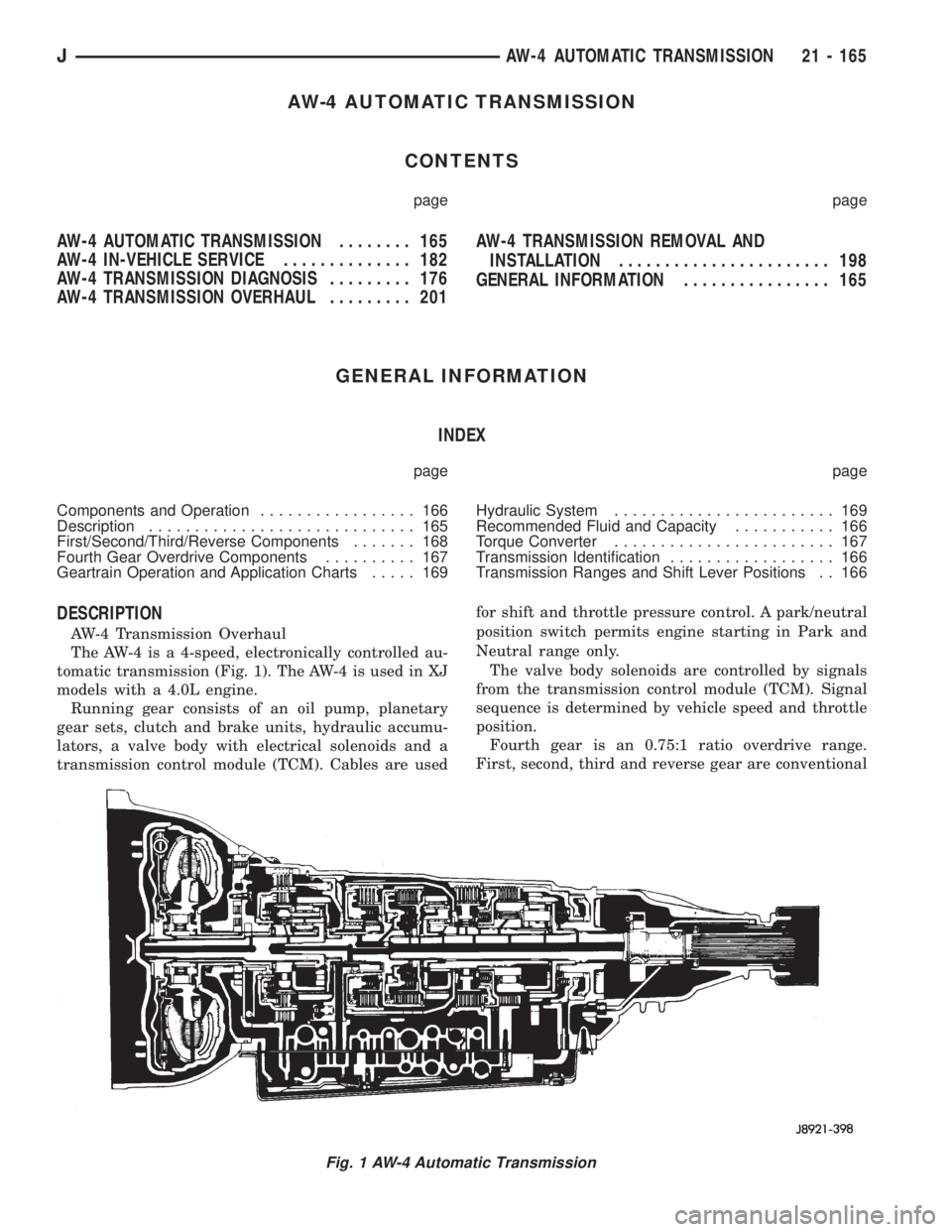
The AW-4 is a 4-speed, electronically controlled au-
tomatic transmission (Fig. 1). The AW-4 is used in XJ
models with a 4.0L engine.
Running gear consists of an oil pump, planetary
gear sets, clutch and brake units, hydraulic accumu-
lators, a valve body with electrical solenoids and a
transmission control module (TCM). Cables are usedfor shift and throttle pressure control. A park/neutral
position switch permits engine starting in Park and
Neutral range only.
The valve body solenoids are controlled by signals
from the transmission control module (TCM). Signal
sequence is determined by vehicle speed and throttle
position.
Fourth gear is an 0.75:1 ratio overdrive range.
First, second, third and reverse gear are conventional
Fig. 1 AW-4 Automatic Transmission
JAW-4 AUTOMATIC TRANSMISSION 21 - 165