1995 JEEP YJ battery
[x] Cancel search: batteryPage 2022 of 2158
EXTERIOR COMPONENTS
INDEX
page page
Battery TrayÐYJ......................... 110
Body Side Step MoldingÐYJ................ 115
Body Stripes/DecalsÐYJ................... 116
Cowl Grille and ScreenÐYJ................ 109
Cowl Weatherstrip SealÐYJ................ 109
Exterior Nameplates (Adhesive-Backed)ÐYJ.... 120
External Spare/Wheel Tire CarrierÐYJ........ 133
Fender FlareÐYJ........................ 114
Fender Inner Splash ShieldsÐYJ............. 116
Fender Splash ApronsÐYJ................. 115
FendersÐYJ............................ 110
Fuel Filler Protector/NozzleÐYJ............. 121
Half Metal Door Mirror (External)ÐYJ......... 121
Hard Top Liftgate GlassÐYJ................ 124
Hard Top RepairÐYJ..................... 127
Hard Top Roof VentÐYJ................... 127
Hard TopÐYJ........................... 126Hood AlignmentÐYJ...................... 107
Hood Insulator PanelÐYJ.................. 107
Hood Safety LatchÐYJ.................... 109
HoodÐYJ.............................. 107
Liftgate Glass Weatherstrip Seal ReplacementÐYJ. 125
Radiator Grille AppliqueÐYJ................ 104
Soft Top Service InformationÐYJ............. 127
Soft Top ServiceÐYJ..................... 129
Sport BarÐYJ........................... 132
Tailgate AdjustmentÐYJ................... 121
Tailgate HingeÐYJ....................... 121
Tailgate Latch and Release HandleÐYJ........ 122
Tailgate Latch StrikerÐYJ.................. 123
Tailgate Lock CylinderÐYJ................. 122
Tailgate Weatherstrip SealÐYJ.............. 123
TailgateÐYJ............................ 121
Wheelhouse Splash LinersÐYJ.............. 115
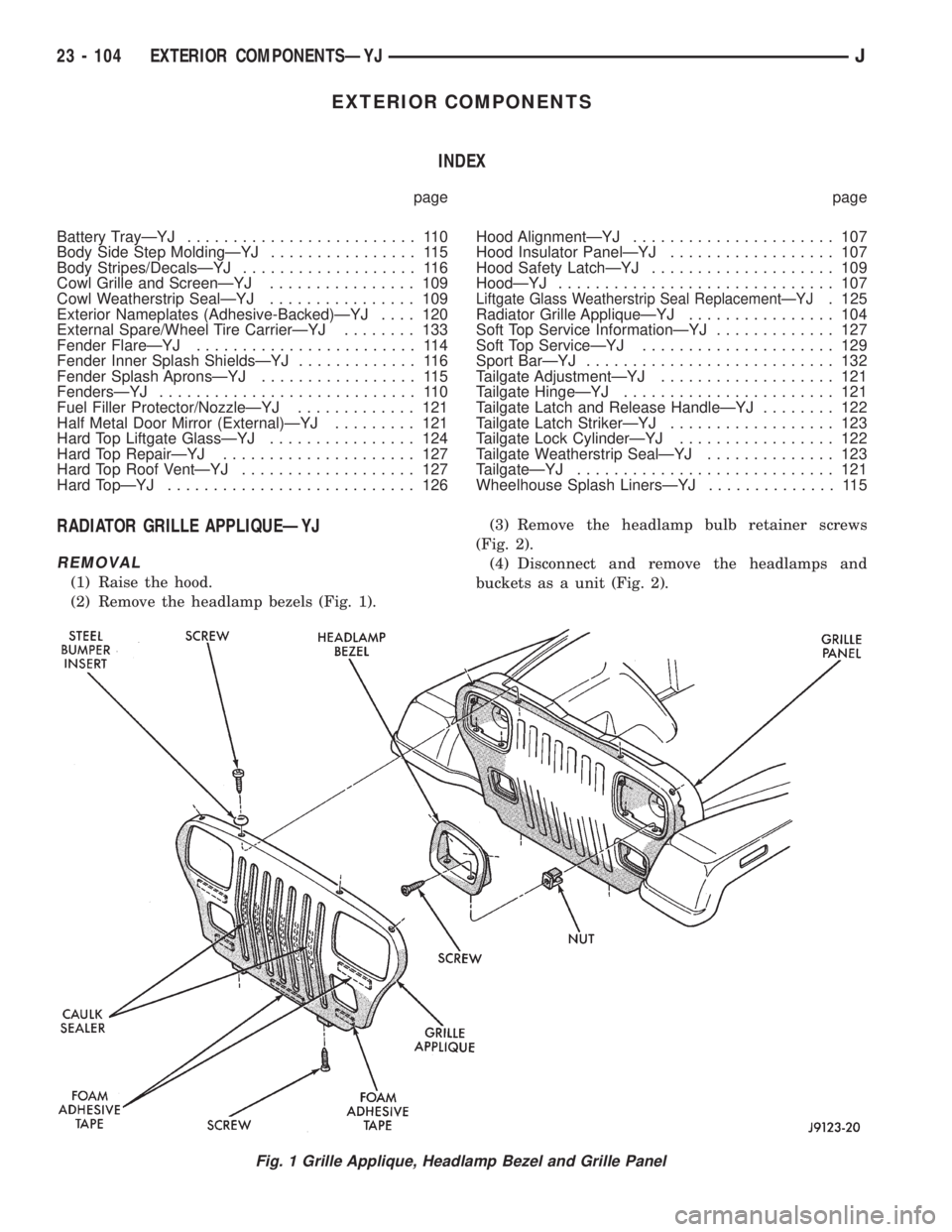
RADIATOR GRILLE APPLIQUEÐYJ
REMOVAL
(1) Raise the hood.
(2) Remove the headlamp bezels (Fig. 1).(3) Remove the headlamp bulb retainer screws
(Fig. 2).
(4) Disconnect and remove the headlamps and
buckets as a unit (Fig. 2).
Fig. 1 Grille Applique, Headlamp Bezel and Grille Panel
23 - 104 EXTERIOR COMPONENTSÐYJJ
Page 2028 of 2158
BATTERY TRAYÐYJ
REMOVAL
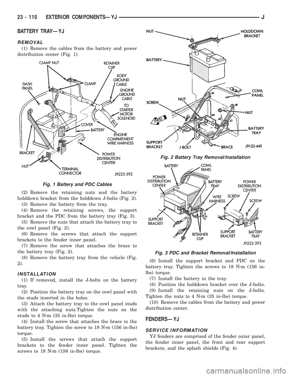
(1) Remove the cables from the battery and power
distribution center (Fig. 1).
(2) Remove the retaining nuts and the battery
holddown bracket from the holddown J-bolts (Fig. 2).
(3) Remove the battery from the tray.
(4) Remove the retaining screws, the support
bracket and the PDC from the battery tray (Fig. 3).
(5) Remove the nuts that attach the battery tray to
the cowl panel (Fig. 2).
(6) Remove the screws that attach the support
brackets to the fender inner panel.
(7) Remove the screw that attaches the brace to
the battery tray (Fig. 2).
(8) Remove the battery tray from the vehicle (Fig.
2).
INSTALLATION
(1) If removed, install the J-bolts on the battery
tray.
(2) Position the battery tray on the cowl panel with
the studs inserted in the holes.
(3) Attach the battery tray to the cowl panel studs
with the attaching nuts.Tighten the nuts on the
studs to 4 Nzm (35 in-lbs) torque.
(4) Install the screw that attaches the brace to the
battery tray. Tighten the screw to 18 Nzm (156 in-lbs)
torque.
(5) Install the screws that attach the support
brackets to the fender inner panel. Tighten the
screws to 18 Nzm (156 in-lbs) torque.(6) Install the support bracket and PDC on the
battery tray. Tighten the screws to 18 Nzm (156 in-
lbs) torque.
(7) Install the battery in the tray.
(8) Position the holddown bracket over the J-bolts.
(9) Install the retaining nuts on the J-bolts.
Tighten the nuts to 4 Nzm (35 in-lbs) torque.
(10) Remove the cables from the battery and power
distribution center.
FENDERSÐYJ
SERVICE INFORMATION
YJ fenders are comprised of the fender outer panel,
the fender inner panel, the front and rear support
brackets, and the splash shields (Fig. 4).
Fig. 1 Battery and PDC Cables
Fig. 2 Battery Tray Removal/Installation
Fig. 3 PDC and Bracket Removal/Installation
23 - 110 EXTERIOR COMPONENTSÐYJJ
Page 2031 of 2158
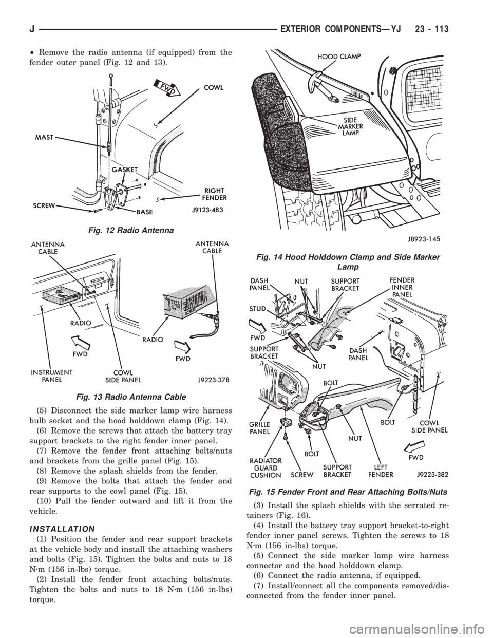
²Remove the radio antenna (if equipped) from the
fender outer panel (Fig. 12 and 13).
(5) Disconnect the side marker lamp wire harness
bulb socket and the hood holddown clamp (Fig. 14).
(6) Remove the screws that attach the battery tray
support brackets to the right fender inner panel.
(7) Remove the fender front attaching bolts/nuts
and brackets from the grille panel (Fig. 15).
(8) Remove the splash shields from the fender.
(9) Remove the bolts that attach the fender and
rear supports to the cowl panel (Fig. 15).
(10) Pull the fender outward and lift it from the
vehicle.
INSTALLATION
(1) Position the fender and rear support brackets
at the vehicle body and install the attaching washers
and bolts (Fig. 15). Tighten the bolts and nuts to 18
Nzm (156 in-lbs) torque.
(2) Install the fender front attaching bolts/nuts.
Tighten the bolts and nuts to 18 Nzm (156 in-lbs)
torque.(3) Install the splash shields with the serrated re-
tainers (Fig. 16).
(4) Install the battery tray support bracket-to-right
fender inner panel screws. Tighten the screws to 18
Nzm (156 in-lbs) torque.
(5) Connect the side marker lamp wire harness
connector and the hood holddown clamp.
(6) Connect the radio antenna, if equipped.
(7) Install/connect all the components removed/dis-
connected from the fender inner panel.
Fig. 12 Radio Antenna
Fig. 13 Radio Antenna Cable
Fig. 14 Hood Holddown Clamp and Side Marker
Lamp
Fig. 15 Fender Front and Rear Attaching Bolts/Nuts
JEXTERIOR COMPONENTSÐYJ 23 - 113
Page 2095 of 2158
HEATING AND AIR CONDITIONING TEST PROCEDURES
INDEX
page page
A/C Compressor Clutch..................... 15
A/C Compressor Clutch Relay................ 15
A/C Compressor Clutch Relay................ 16
Air Conditioning ControlsÐXJ Vehicles......... 15
Air Conditioning ControlsÐYJ Vehicles......... 16
Blower Motor............................ 17
Blower Motor Switch....................... 16Compressor Clutch........................ 16
Fin Sensing Cycling Clutch Switch............. 15
Heater Diagnosis......................... 17
Low-Pressure High-Pressure Cut-Off Switch..... 15
Low-Pressure High-Pressure Cut-Off Switch..... 16
Thermostatic Control....................... 16
AIR CONDITIONING CONTROLSÐXJ VEHICLES
The A/C Compressor Clutch is controlled by several
components: the Pressure Cut-Off Switch, Cycling
Clutch Switch, Clutch Relay and Powertrain Control
Module (PCM).
Powertrain Control Module may delay A/C clutch
engagement up to 30 seconds.
Refer to Group 8W Wiring Diagrams for wiring and
terminals. Use volt ohmmeter to test switches.
A/C COMPRESSOR CLUTCH
The clutch assembly consists of a stationary elec-
tromagnetic coil, hub bearing pulley assembly, and
clutch plate. When the coil is energized the plate is
magnetically engaged with the pulley and turns the
compressor shaft.
A/C COMPRESSOR CLUTCH TEST
(1) Unplug clutch coil connector.
(2) Connect a jumper wire from the battery posi-
tive post to the clutch coil terminal. The clutch
should engage, if not leave jumper wire connected
and go to next step.
(3) Connect a jumper wire from clutch coil frame to
chassis ground. The clutch should engage if not re-
pair clutch coil ground or replace coil.
A/C COMPRESSOR CLUTCH RELAY
The A/C compressor clutch relay controls the 12-
volt source to the A/C clutch. The relay is activated
when the PCM receives a A/C request signal from the
fin-sensed cycling clutch switch. The PCM then sends
a ground signal to the relay. The relay is activated
and sends 12-volts to the clutch coil which energizes
the clutch. The relay is located in the power distribu-
tion center.
COMPRESSOR CLUTCH RELAY TEST
For test procedure refer to Powertrain Diagnostic
Service Manual for A/C clutch relay circuit test.
LOW-PRESSURE HIGH-PRESSURE CUT-OFF
SWITCH
The pressure cut-off switch is located on the filter
drier and is wired in series with compressor clutch.
The switch interrupts the power to the compressor
clutch circuit when the pressure drops to 193 kPa (28
psi) or increases above 3100 to 3375 kPa (450 to 490
psi).
PRESSURE CUT-OFF SWITCH TEST
(1) Verify system has correct refrigerant charge.
(2) Turn ignition switch to RUN, A/C blower switch
to ON and control set to MAX.
(3) Unplug pressure cut-off switch and test feed
circuit from select switch. It should be battery volt-
age if not, repair open to select switch.
(4) Test for continuity between the switch termi-
nals. If continuity is not present recover refrigerant
from the system. Replace switch, evacuate and re-
charge system.
FIN SENSING CYCLING CLUTCH SWITCH
The switch is attached to the evaporator coil with
the temperature sensing probe inserted into the coil
fins. This switch prevents condensate water on the
evaporator coil from freezing. It does this by sending
signals to the PCM to cycling the compressor clutch
on and off.
FIN-SENSED CYCLING CLUTCH SWITCH TEST
Test area ambient temperature should be around
21ÉC (70ÉF) for test.
(1) Verify system has correct refrigerant charge.
(2) Start Engine and turn on A/C.
(3) If the compressor clutch cycles ON and OFF 2
to 3 times per minute the cycling clutch switch is
normal. The ambient temperature should be between
20ÉC-30ÉC (68ÉF-90ÉF). Above 32ÉC (90ÉF) the com-
pressor clutch may stay engaged (non cycling) due to
the high heat load, this condition is normal. If the
compressor clutch fails to engage go to next step.
(4) Disconnect wiring harness connector from
switch. With a volt meter test feed circuit from cut-
JHEATING AND AIR CONDITIONING 24 - 15
Page 2096 of 2158
off switch for battery voltage. If no voltage is present
test pressure cut-off switch. If voltage is present go
to next step.
(5) With ohmmeter test harness connector ground
circuit for continuity to ground. If circuit is open, (no
continuity) repair ground circuit. If circuit test OK
and clutch does not engage refer to Powertrain Diag-
nostic Service Manual for A/C clutch circuit test.
AIR CONDITIONING CONTROLSÐYJ VEHICLES
The air conditioning circuit consists of 3 segments;
battery supply, blower motor and compressor clutch.
The 3 segments have a common connection point at
the blower switch.
The power supply circuit extends from the HTR/
FAN fuse to the blower switch. From the blower
switch, battery feed is routed to the blower motor
and compressor clutch circuit.
Refer to Group 8W Wiring Diagrams for wiring
schematic and terminals. Use volt ohmmeter to test
switches.
COMPRESSOR CLUTCH
The clutch assembly consists of a stationary elec-
tromagnetic coil, hub bearing pulley assembly, and
clutch plate. When the coil is energized the plate is
magnetically engaged with the pulley and turns the
compressor shaft.
COMPRESSOR CLUTCH TEST
(1) Unplug clutch coil connector.
(2) Connect jumper wire from battery positive post
to clutch coil connector. The clutch should engage, if
not leave jumper wire connected and go to next step.
(3) Connect jumper wire from clutch coil frame to
chassis ground. The clutch should engage, if not re-
pair clutch coil ground or replace coil.
A/C COMPRESSOR CLUTCH RELAY
The A/C compressor clutch relay controls the 12-
volt source to the A/C clutch. The relay is activated
when the PCM receives a A/C request signal. The
PCM then sends a ground signal to the relay. The re-
lay is activated and sends 12-volts to the clutch coil
which energizes the clutch. The relay is located in
the power distribution center.
COMPRESSOR CLUTCH RELAY TEST
For test procedure refer to Powertrain Diagnostic
Service Manual for A/C clutch relay circuit test.
LOW-PRESSURE HIGH-PRESSURE CUT-OFF
SWITCH
The pressure cut-off switch is located on the filter
drier and is wired in series with compressor clutch.
The switch interrupts the power to the compressorclutch circuit when the pressure drops to 193 kPa (28
psi) or increases above 3100 to 3375 kPa (450 to 490
psi).
PRESSURE CUT-OFF SWITCH TEST
(1) Turn ignition switch to RUN, A/C blower switch
to ON and control set to MAX.
(2) Unplug pressure cut-off switch connector and
test feed circuit from the thermostatic, should be bat-
tery voltage. If not, proceed to thermostatic control
tests.
(3) Test for continuity between the switch termi-
nals. If continuity is not present recover refrigerant
system, replace switch, evacuate and recharge sys-
tem.
THERMOSTATIC CONTROL
Cycling of the compressor and therefore the tem-
perature of the outlet air is regulated by the thermo-
static control. A thermal sensor extends from the
control to the evaporator housing. When the temper-
ature of the evaporator drops below the set tempera-
ture, the thermostatic control opens the clutch
circuit. The circuit remains open until evaporator
temperature rises above the set temperature.
THERMOSTATIC CONTROL TEST
(1) Turn ignition switch to RUN, A/C blower switch
to ON and thermostatic control set to MAX cool.
(2) Test thermostatic control feed terminal from
blower switch, should be battery voltage. If not re-
pair open from blower switch.
(3) Test thermostatic control output terminal to
pressure cut-out switch, should be battery voltage. If
not, replace thermostatic control.
BLOWER MOTOR SWITCH
The blower switch controls blower motor speed.
The blower motor segment consists of the 3 wires
from the blower switch to the motor. Through the
switch, the 3 wires connect the motor brushes to bat-
tery supply. When connected to battery feed, the sep-
arate brushes provide the 3 blower speeds LO, MED,
and HIGH.
BLOWER MOTOR SWITCH TEST
(1) Turn ignition to RUN position.
(2) Test battery side of fuse for battery voltage. If
not, repair open from ignition switch.
(3) Test A/C blower switch feed circuit from fuse
box should be battery voltage. If not, repair open
from fuse panel.
(4) Test A/C blower switch LO terminal with
blower switch in LO, should be battery voltage. If
not, replace switch.
(5) Test A/C blower switch MED terminal with
blower switch in MED, should be battery voltage. If
not, replace switch.
24 - 16 HEATING AND AIR CONDITIONINGJ
Page 2097 of 2158
(6) Test A/C blower switch HIGH terminal with
blower switch in HIGH, should be battery voltage. If
not, replace switch.
BLOWER MOTOR
The A/C blower motor is attached to the evaporator
housing mounted under the instrument panel. The
motor has a ground wire and 3 wires connect to the
motor brushes. When voltage is applied to the sepa-
rate brushes it provides the 3 blower speeds LO,
MED, and HIGH.
BLOWER MOTOR TEST
Turn ignition switch to RUN for voltage tests and
turn ignition switch to OFF for resistance test.
(1) Test A/C blower motor ground terminal should
be 0 ohms. If not, repair ground circuit.
(2) Test A/C blower motor connector LO terminal
with blower switch in LO, should be battery voltage.
If not repair open from blower switch. If the blower
motor is still inoperative replace motor.
(3) Test A/C blower motor connector MED terminal
with blower switch in MED, should be battery volt-
age. If not repair open from blower switch. If the
blower motor is still inoperative replace motor.
(4) Test A/C blower motor connector HIGH termi-
nal with blower switch in HIGH, should be battery
voltage. If not, repair open from blower switch. If the
blower motor is still inoperative, replace motor.
HEATER DIAGNOSIS
On LHD XJ vehicles a water valve controls coolant
flow to the heater core. The valve is vacuum oper-
ated. When vacuum is applied, the valve opens and
coolant is directed through the heater core and back
to the engine. When the water valve is closed (no
vacuum applied) coolant flow bypasses the heater
core back to the engine.
The heating system receives its battery feed from
the fuse box. On YJ vehicles the feed circuit runs to
the HEATER/OFF switch and then to the BLOWER
switch. On XJ vehicles the feed circuit runs to the
HEAT/MODE switch and then to the BLOWER
switch.
The blower speed is controlled by the blower switch
and blower resistors. With the switch in LO, battery
voltage is supplied to the motor through all of the re-
sistors. The motor runs slowly. When the blower
switch is moved to a higher speed, battery voltage in-
creases to the blower motor which increase its speed.
This is accomplished by bypassing some of the blower
resistors. When the switch is in HI, blower resistors
are bypassed and battery voltage is applied directly
to the blower motor.
The following chart has been developed for quick
reference.
Refer to the Group 8W Wiring Diagrams for com-
plete wiring schematic.
JHEATING AND AIR CONDITIONING 24 - 17
Page 2099 of 2158
COMPRESSOR SERVICE
DESCRIPTION
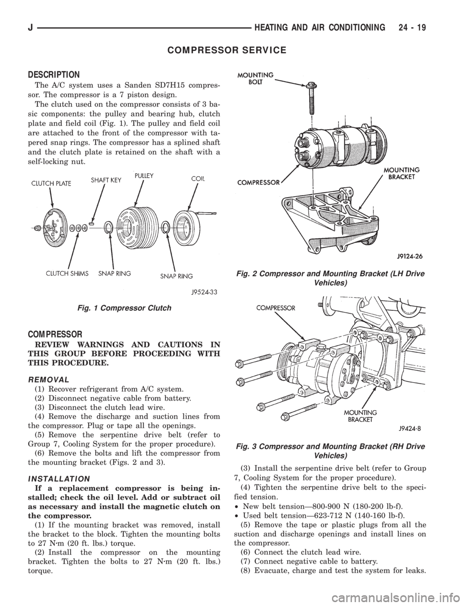
The A/C system uses a Sanden SD7H15 compres-
sor. The compressor is a 7 piston design.
The clutch used on the compressor consists of 3 ba-
sic components: the pulley and bearing hub, clutch
plate and field coil (Fig. 1). The pulley and field coil
are attached to the front of the compressor with ta-
pered snap rings. The compressor has a splined shaft
and the clutch plate is retained on the shaft with a
self-locking nut.
COMPRESSOR
REVIEW WARNINGS AND CAUTIONS IN
THIS GROUP BEFORE PROCEEDING WITH
THIS PROCEDURE.
REMOVAL
(1) Recover refrigerant from A/C system.
(2) Disconnect negative cable from battery.
(3) Disconnect the clutch lead wire.
(4) Remove the discharge and suction lines from
the compressor. Plug or tape all the openings.
(5) Remove the serpentine drive belt (refer to
Group 7, Cooling System for the proper procedure).
(6) Remove the bolts and lift the compressor from
the mounting bracket (Figs. 2 and 3).
INSTALLATION
If a replacement compressor is being in-
stalled; check the oil level. Add or subtract oil
as necessary and install the magnetic clutch on
the compressor.
(1) If the mounting bracket was removed, install
the bracket to the block. Tighten the mounting bolts
to 27 Nzm (20 ft. lbs.) torque.
(2) Install the compressor on the mounting
bracket. Tighten the bolts to 27 Nzm (20 ft. lbs.)
torque.(3) Install the serpentine drive belt (refer to Group
7, Cooling System for the proper procedure).
(4) Tighten the serpentine drive belt to the speci-
fied tension.
²New belt tensionÐ800-900 N (180-200 lb-f).
²Used belt tensionÐ623-712 N (140-160 lb-f).
(5) Remove the tape or plastic plugs from all the
suction and discharge openings and install lines on
the compressor.
(6) Connect the clutch lead wire.
(7) Connect negative cable to battery.
(8) Evacuate, charge and test the system for leaks.
Fig. 1 Compressor Clutch
Fig. 2 Compressor and Mounting Bracket (LH Drive
Vehicles)
Fig. 3 Compressor and Mounting Bracket (RH Drive
Vehicles)
JHEATING AND AIR CONDITIONING 24 - 19
Page 2103 of 2158
COMPONENT SERVICEÐXJ VEHICLES
INDEX
page page
A/C Recirculating Door Vacuum Motor
Replacement........................... 27
Blower Motor Resistors Replacement.......... 31
Blower Motor/Fan Replacement............... 24
Condenser Filter DrierÐ2.5L Engines.......... 27
CondenserÐ4.0L Engines................... 28
Description.............................. 23
Evaporator Coil........................... 30
Evaporator/Blower Housing.................. 29Expansion Valve.......................... 31
Filter DrierÐ4.0L Engines................... 28
Fin Sensing Cycling Clutch Switch............. 31
Heater and A/C Control Replacement.......... 23
Heater Core............................. 26
Heater Housing Replacement................ 26
Heater/Defroster/Instrument Panel Outlet Vacuum
Motor Replacement...................... 26
DESCRIPTION
The Climate Control System combines air condi-
tioning, heating and ventilating capabilities for vehi-
cles equipped with air conditioning. Vehicles without
air conditioning perform heating and ventilating
functions without the air conditioning evaporator.
Both systems consist basically of 2 parts:
²Blower and Air Inlet Assembly
²Heater Core and Air Distribution Assembly
These unit may be removed separately from under
the instrument panel for service.
HEATER AND A/C CONTROL REPLACEMENT
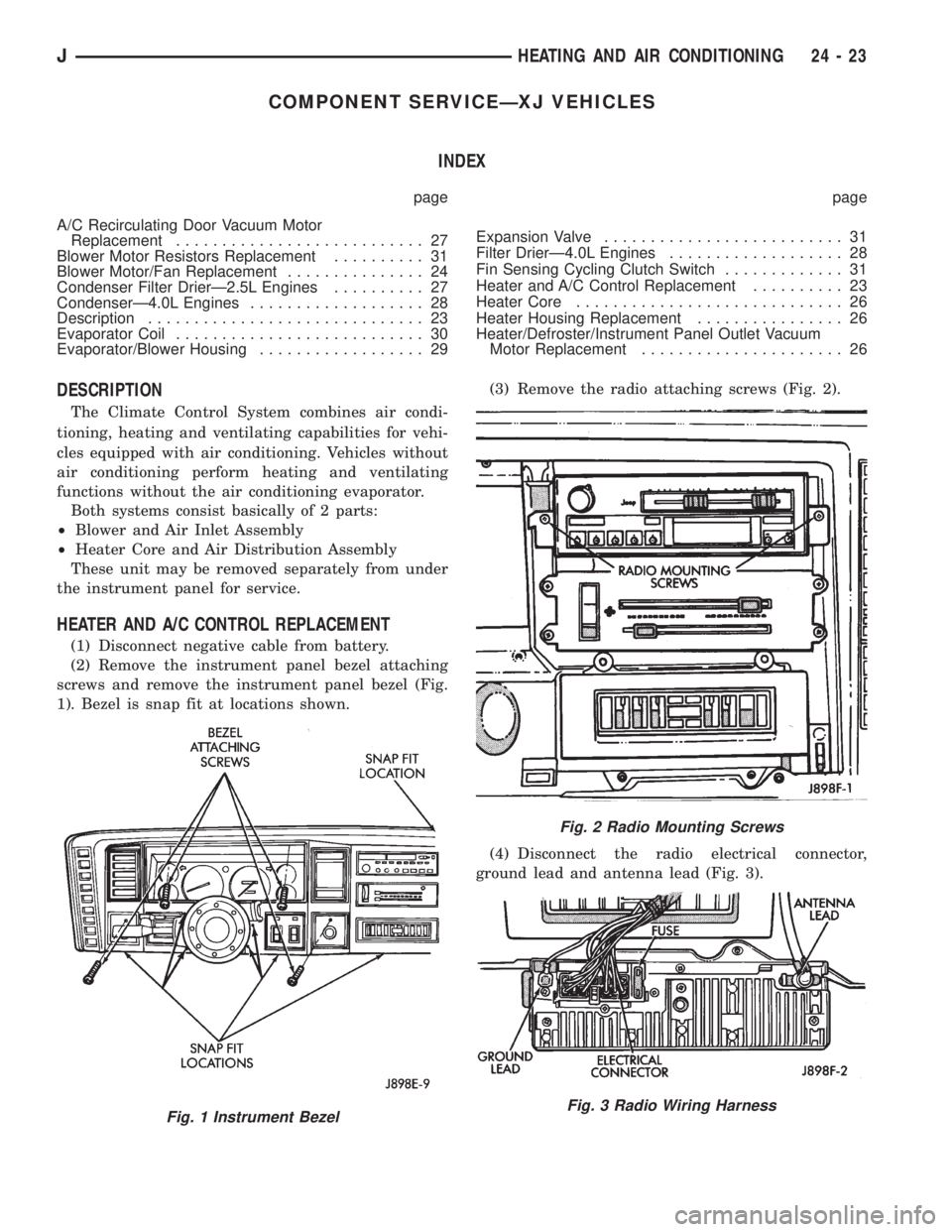
(1) Disconnect negative cable from battery.
(2) Remove the instrument panel bezel attaching
screws and remove the instrument panel bezel (Fig.
1). Bezel is snap fit at locations shown.(3) Remove the radio attaching screws (Fig. 2).
(4) Disconnect the radio electrical connector,
ground lead and antenna lead (Fig. 3).
Fig. 1 Instrument Bezel
Fig. 2 Radio Mounting Screws
Fig. 3 Radio Wiring Harness
JHEATING AND AIR CONDITIONING 24 - 23