1995 JEEP YJ battery
[x] Cancel search: batteryPage 1533 of 2158
AIRBAG MODULE REMOVEÐINSTALL
WARNING: THIS AIRBAG SYSTEM IS A SENSITIVE,
COMPLEX MECHANICAL UNIT. BEFORE ATTEMPT-
ING TO REMOVE OR INSTALL THE AIRBAG SYS-
TEM OR RELATED STEERING WHEEL AND
STEERING COLUMN COMPONENTS YOU MUST
FIRST DISARM THE AIRBAG FIRING MECHANISM.
FAILURE TO DO SO COULD RESULT IN ACCIDEN-
TAL DEPLOYMENT AND POSSIBLE PERSONAL IN-
JURY.
When removing a deployed airbag module,
rubber gloves, eye protection and long-sleeved
shirt should be worn. There may be deposits on
the airbag module and other interior surfaces,
which can cause irritation to the skin and eyes
in large doses.
(1) Disconnect battery negative cable and isolate.
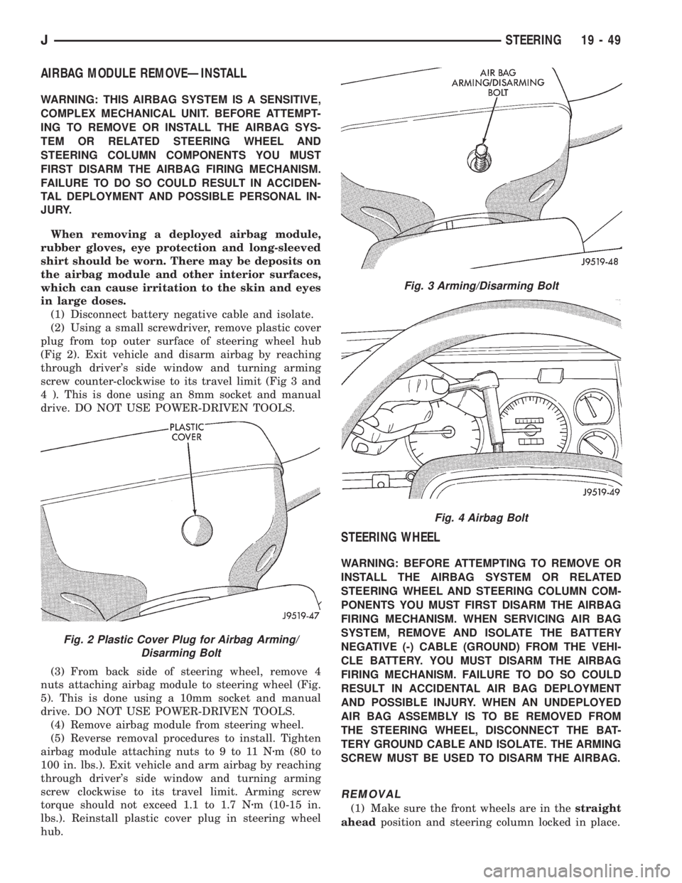
(2) Using a small screwdriver, remove plastic cover
plug from top outer surface of steering wheel hub
(Fig 2). Exit vehicle and disarm airbag by reaching
through driver's side window and turning arming
screw counter-clockwise to its travel limit (Fig 3 and
4 ). This is done using an 8mm socket and manual
drive. DO NOT USE POWER-DRIVEN TOOLS.
(3) From back side of steering wheel, remove 4
nuts attaching airbag module to steering wheel (Fig.
5). This is done using a 10mm socket and manual
drive. DO NOT USE POWER-DRIVEN TOOLS.
(4) Remove airbag module from steering wheel.
(5) Reverse removal procedures to install. Tighten
airbag module attaching nuts to 9 to 11 Nzm (80 to
100 in. lbs.). Exit vehicle and arm airbag by reaching
through driver's side window and turning arming
screw clockwise to its travel limit. Arming screw
torque should not exceed 1.1 to 1.7 Nzm (10-15 in.
lbs.). Reinstall plastic cover plug in steering wheel
hub.
STEERING WHEEL
WARNING: BEFORE ATTEMPTING TO REMOVE OR
INSTALL THE AIRBAG SYSTEM OR RELATED
STEERING WHEEL AND STEERING COLUMN COM-
PONENTS YOU MUST FIRST DISARM THE AIRBAG
FIRING MECHANISM. WHEN SERVICING AIR BAG
SYSTEM, REMOVE AND ISOLATE THE BATTERY
NEGATIVE (-) CABLE (GROUND) FROM THE VEHI-
CLE BATTERY. YOU MUST DISARM THE AIRBAG
FIRING MECHANISM. FAILURE TO DO SO COULD
RESULT IN ACCIDENTAL AIR BAG DEPLOYMENT
AND POSSIBLE INJURY. WHEN AN UNDEPLOYED
AIR BAG ASSEMBLY IS TO BE REMOVED FROM
THE STEERING WHEEL, DISCONNECT THE BAT-
TERY GROUND CABLE AND ISOLATE. THE ARMING
SCREW MUST BE USED TO DISARM THE AIRBAG.
REMOVAL
(1) Make sure the front wheels are in thestraight
aheadposition and steering column locked in place.
Fig. 2 Plastic Cover Plug for Airbag Arming/
Disarming Bolt
Fig. 3 Arming/Disarming Bolt
Fig. 4 Airbag Bolt
JSTEERING 19 - 49
Page 1534 of 2158
(2) Disconnect the battery negative (ground) cable
and isolate.
(3) Disarm the airbag (refer to group 8M, Electri-
cal for proper and safe procedures).
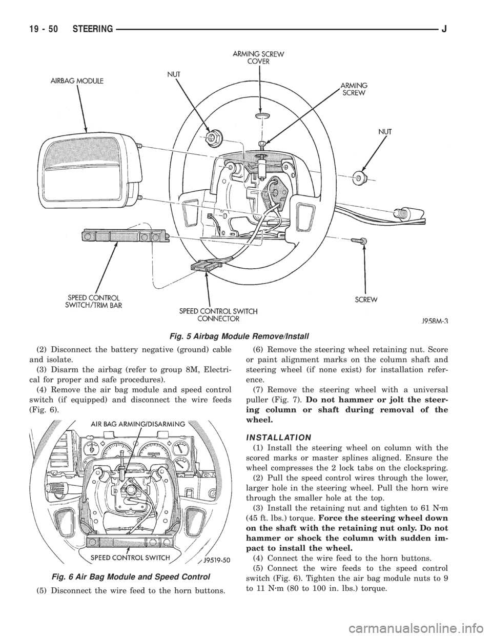
(4) Remove the air bag module and speed control
switch (if equipped) and disconnect the wire feeds
(Fig. 6).
(5) Disconnect the wire feed to the horn buttons.(6) Remove the steering wheel retaining nut. Score
or paint alignment marks on the column shaft and
steering wheel (if none exist) for installation refer-
ence.
(7) Remove the steering wheel with a universal
puller (Fig. 7).Do not hammer or jolt the steer-
ing column or shaft during removal of the
wheel.
INSTALLATION
(1) Install the steering wheel on column with the
scored marks or master splines aligned. Ensure the
wheel compresses the 2 lock tabs on the clockspring.
(2) Pull the speed control wires through the lower,
larger hole in the steering wheel. Pull the horn wire
through the smaller hole at the top.
(3) Install the retaining nut and tighten to 61 Nzm
(45 ft. lbs.) torque.Force the steering wheel down
on the shaft with the retaining nut only. Do not
hammer or shock the column with sudden im-
pact to install the wheel.
(4) Connect the wire feed to the horn buttons.
(5) Connect the wire feeds to the speed control
switch (Fig. 6). Tighten the air bag module nuts to 9
to 11 Nzm (80 to 100 in. lbs.) torque.
Fig. 5 Airbag Module Remove/Install
Fig. 6 Air Bag Module and Speed Control
19 - 50 STEERINGJ
Page 1535 of 2158
CLOCKSPRING
WARNING: BEFORE SERVICING AIR BAG SYSTEM,
REMOVE AND ISOLATE BATTERY NEGATIVE (-) CA-
BLE (GROUND) FROM VEHICLE BATTERY. WHEN
AN UNDEPLOYED AIR BAG ASSEMBLY IS TO BE
REMOVED FROM THE STEERING WHEEL, DISCON-
NECT THE BATTERY GROUND CABLE AND ISO-
LATE.
REMOVAL
(1) Place the front wheels in the straight ahead po-
sition before starting the repair.
(2) Disconnect battery negative cable and isolate.
(3) Remove the steering wheel and air bag, refer to
Steering Wheel Removal.
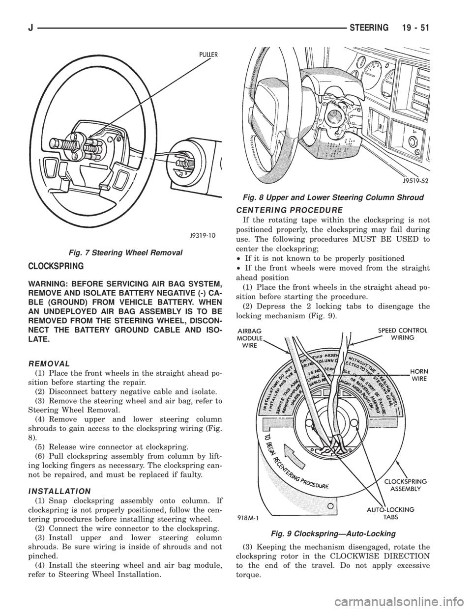
(4) Remove upper and lower steering column
shrouds to gain access to the clockspring wiring (Fig.
8).
(5) Release wire connector at clockspring.
(6) Pull clockspring assembly from column by lift-
ing locking fingers as necessary. The clockspring can-
not be repaired, and must be replaced if faulty.
INSTALLATION
(1) Snap clockspring assembly onto column. If
clockspring is not properly positioned, follow the cen-
tering procedures before installing steering wheel.
(2) Connect the wire connector to the clockspring.
(3) Install upper and lower steering column
shrouds. Be sure wiring is inside of shrouds and not
pinched.
(4) Install the steering wheel and air bag module,
refer to Steering Wheel Installation.
CENTERING PROCEDURE
If the rotating tape within the clockspring is not
positioned properly, the clockspring may fail during
use. The following procedures MUST BE USED to
center the clockspring;
²If it is not known to be properly positioned
²If the front wheels were moved from the straight
ahead position
(1) Place the front wheels in the straight ahead po-
sition before starting the procedure.
(2) Depress the 2 locking tabs to disengage the
locking mechanism (Fig. 9).
(3) Keeping the mechanism disengaged, rotate the
clockspring rotor in the CLOCKWISE DIRECTION
to the end of the travel. Do not apply excessive
torque.
Fig. 7 Steering Wheel Removal
Fig. 8 Upper and Lower Steering Column Shroud
Fig. 9 ClockspringÐAuto-Locking
JSTEERING 19 - 51
Page 1536 of 2158
(4) From the end of travel, rotate the rotor 2 1/2
full turns in the COUNTER CLOCKWISE direction.
The horn wire should end up at the top and the
squib wire at the bottom (Fig. 9).
(5) Install the steering wheel and air bag module,
refer to Steering Wheel Installation.
COLUMN ASSEMBLY REPLACEMENT
CAUTION: Bumping, jolting and hammering on the
steering column shaft and gear shift tube must be
avoided during all service procedures.
REMOVAL
(1) Make sure the front wheels are in thestraight
aheadposition.
(2) Observe Cautions and disconnect the negative
(ground) cable from the battery.
(3) Disarm airbag, refer to Arming/Disarming Air-
bag in this section.
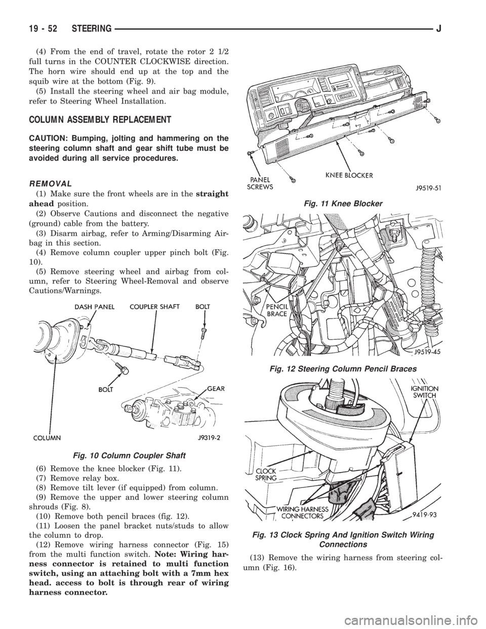
(4) Remove column coupler upper pinch bolt (Fig.
10).
(5) Remove steering wheel and airbag from col-
umn, refer to Steering Wheel-Removal and observe
Cautions/Warnings.
(6) Remove the knee blocker (Fig. 11).
(7) Remove relay box.
(8) Remove tilt lever (if equipped) from column.
(9) Remove the upper and lower steering column
shrouds (Fig. 8).
(10) Remove both pencil braces (fig. 12).
(11) Loosen the panel bracket nuts/studs to allow
the column to drop.
(12) Remove wiring harness connector (Fig. 15)
from the multi function switch.Note: Wiring har-
ness connector is retained to multi function
switch, using an attaching bolt with a 7mm hex
head. access to bolt is through rear of wiring
harness connector.(13) Remove the wiring harness from steering col-
umn (Fig. 16).
Fig. 10 Column Coupler Shaft
Fig. 11 Knee Blocker
Fig. 12 Steering Column Pencil Braces
Fig. 13 Clock Spring And Ignition Switch Wiring
Connections
19 - 52 STEERINGJ
Page 1538 of 2158
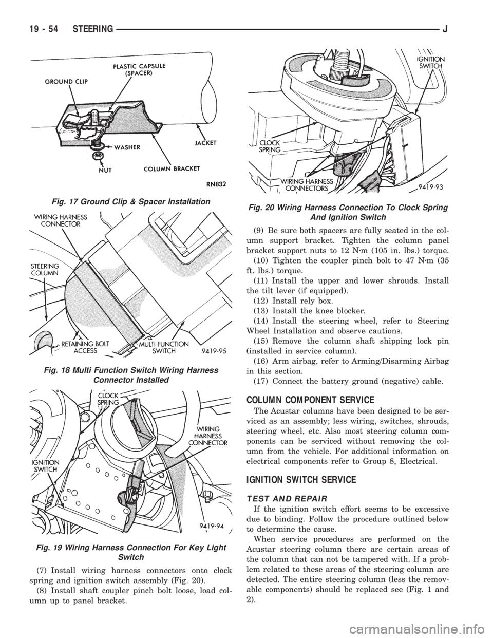
(7) Install wiring harness connectors onto clock
spring and ignition switch assembly (Fig. 20).
(8) Install shaft coupler pinch bolt loose, load col-
umn up to panel bracket.(9) Be sure both spacers are fully seated in the col-
umn support bracket. Tighten the column panel
bracket support nuts to 12 Nzm (105 in. lbs.) torque.
(10) Tighten the coupler pinch bolt to 47 Nzm (35
ft. lbs.) torque.
(11) Install the upper and lower shrouds. Install
the tilt lever (if equipped).
(12) Install rely box.
(13) Install the knee blocker.
(14) Install the steering wheel, refer to Steering
Wheel Installation and observe cautions.
(15) Remove the column shaft shipping lock pin
(installed in service column).
(16) Arm airbag, refer to Arming/Disarming Airbag
in this section.
(17) Connect the battery ground (negative) cable.
COLUMN COMPONENT SERVICE
The Acustar columns have been designed to be ser-
viced as an assembly; less wiring, switches, shrouds,
steering wheel, etc. Also most steering column com-
ponents can be serviced without removing the col-
umn from the vehicle. For additional information on
electrical components refer to Group 8, Electrical.
IGNITION SWITCH SERVICE
TEST AND REPAIR
If the ignition switch effort seems to be excessive
due to binding. Follow the procedure outlined below
to determine the cause.
When service procedures are performed on the
Acustar steering column there are certain areas of
the column that can not be tampered with. If a prob-
lem related to these areas of the steering column are
detected. The entire steering column (less the remov-
able components) should be replaced see (Fig. 1 and
2).
Fig. 17 Ground Clip & Spacer Installation
Fig. 18 Multi Function Switch Wiring Harness
Connector Installed
Fig. 19 Wiring Harness Connection For Key Light
Switch
Fig. 20 Wiring Harness Connection To Clock Spring
And Ignition Switch
19 - 54 STEERINGJ
Page 1542 of 2158
STEERING COLUMNÐYJ
INDEX
page page
Assembly............................... 63
Assembly............................... 71
Column Replacement...................... 58
Disassembly............................. 66DisassemblyÐColumn or Console Shift......... 60
Non-Tilt Steering Column................... 60
Steering Wheel........................... 58
Tilt Steering Column....................... 66
The column may be disassembled and reassembled.
Also most steering column components can be serviced
without removing the column from the vehicle. For ad-
ditional information, refer to Group 8H, Electrical.
CAUTION: Bumping, jolting and hammering on the
steering column shaft and gear shift tube must be
avoided during all service procedures.
CAUTION: Disconnect negative (ground) cable from the
battery before servicing any component on the column.
Safety goggles should be worn at all times
when involved with steering column service.
STEERING WHEEL
REMOVAL
(1) Make sure the front wheels are in thestraight
aheadposition.
(2) Disconnect the negative (ground) cable from the
battery.
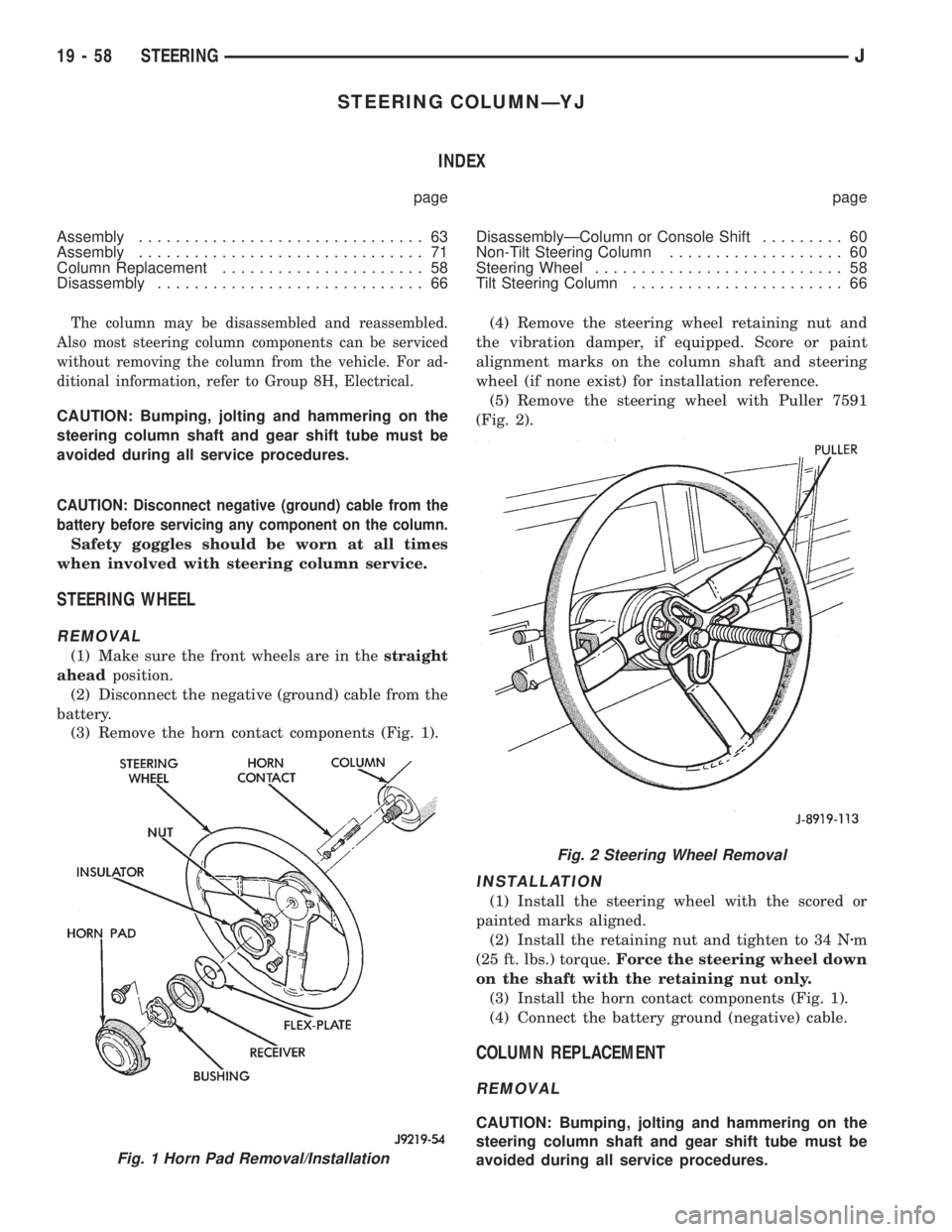
(3) Remove the horn contact components (Fig. 1).(4) Remove the steering wheel retaining nut and
the vibration damper, if equipped. Score or paint
alignment marks on the column shaft and steering
wheel (if none exist) for installation reference.
(5) Remove the steering wheel with Puller 7591
(Fig. 2).
INSTALLATION
(1) Install the steering wheel with the scored or
painted marks aligned.
(2) Install the retaining nut and tighten to 34 Nzm
(25 ft. lbs.) torque.Force the steering wheel down
on the shaft with the retaining nut only.
(3) Install the horn contact components (Fig. 1).
(4) Connect the battery ground (negative) cable.
COLUMN REPLACEMENT
REMOVAL
CAUTION: Bumping, jolting and hammering on the
steering column shaft and gear shift tube must be
avoided during all service procedures.
Fig. 1 Horn Pad Removal/Installation
Fig. 2 Steering Wheel Removal
19 - 58 STEERINGJ
Page 1543 of 2158
(1) Make sure the front wheels are in thestraight
aheadposition.
(2) Disconnect the negative (ground) cable from the
battery.
(3) Remove steering wheel from column, refer to
Steering Wheel-Removal.
(4) Column shift vehicles, disconnect the shift ca-
ble grommet by prying it from the shift lever.
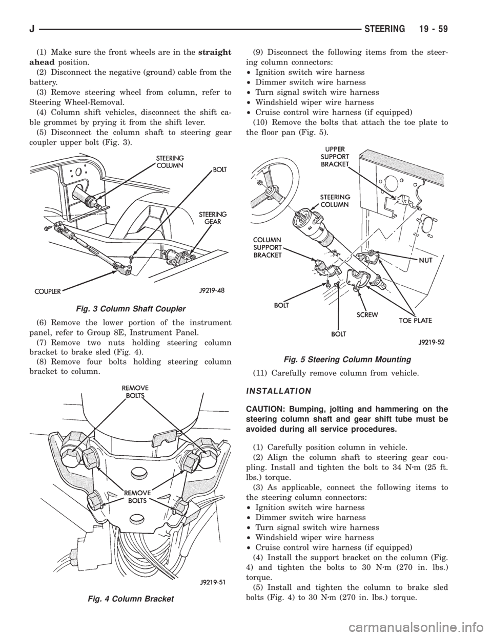
(5) Disconnect the column shaft to steering gear
coupler upper bolt (Fig. 3).
(6) Remove the lower portion of the instrument
panel, refer to Group 8E, Instrument Panel.
(7) Remove two nuts holding steering column
bracket to brake sled (Fig. 4).
(8) Remove four bolts holding steering column
bracket to column.(9) Disconnect the following items from the steer-
ing column connectors:
²Ignition switch wire harness
²Dimmer switch wire harness
²Turn signal switch wire harness
²Windshield wiper wire harness
²Cruise control wire harness (if equipped)
(10) Remove the bolts that attach the toe plate to
the floor pan (Fig. 5).
(11) Carefully remove column from vehicle.
INSTALLATION
CAUTION: Bumping, jolting and hammering on the
steering column shaft and gear shift tube must be
avoided during all service procedures.
(1) Carefully position column in vehicle.
(2) Align the column shaft to steering gear cou-
pling. Install and tighten the bolt to 34 Nzm (25 ft.
lbs.) torque.
(3) As applicable, connect the following items to
the steering column connectors:
²Ignition switch wire harness
²Dimmer switch wire harness
²Turn signal switch wire harness
²Windshield wiper wire harness
²Cruise control wire harness (if equipped)
(4) Install the support bracket on the column (Fig.
4) and tighten the bolts to 30 Nzm (270 in. lbs.)
torque.
(5) Install and tighten the column to brake sled
bolts (Fig. 4) to 30 Nzm (270 in. lbs.) torque.
Fig. 3 Column Shaft Coupler
Fig. 4 Column Bracket
Fig. 5 Steering Column Mounting
JSTEERING 19 - 59
Page 1544 of 2158
(6) Column shift vehicles, install the shift cable
grommet on the shift lever.
(7) Install and tighten the toe plate to floor pan
bolts/nuts to 21.5 Nzm (192 in. lbs.) torque (Fig. 5).
(8) Install the lower portion of the instrument
panel, refer to Group 8E, Instrument Panel.
(9) Install steering wheel on column, refer to Steer-
ing Wheel-Installation.
(10) Connect the negative (ground) cable to the
battery.
NON-TILT STEERING COLUMN
DISASSEMBLYÐCOLUMN OR CONSOLE SHIFT
Steering column removal from the vehicle is not
necessary for;
²Lockplate cover
²Lockplate
²Steering shaft retaining ring
²Canceling cam
²Turn signal switch
²Upper bearing preload spring
²Ignition key/lock cylinder service
The steering column must be removed from
the vehicle to service any other component.
(1) If the column is removed for service, fabricate a
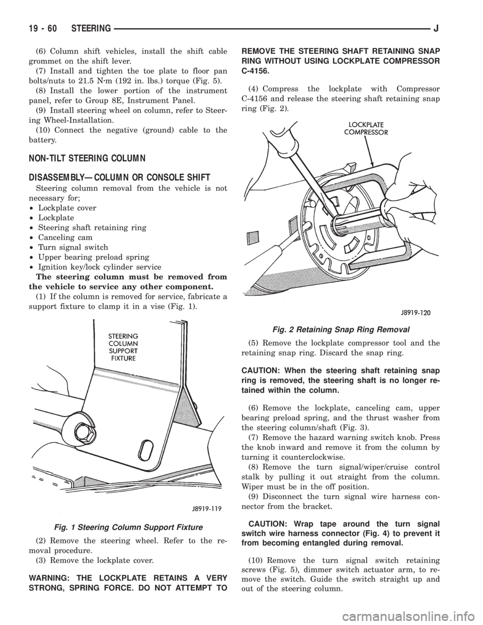
support fixture to clamp it in a vise (Fig. 1).
(2) Remove the steering wheel. Refer to the re-
moval procedure.
(3) Remove the lockplate cover.
WARNING: THE LOCKPLATE RETAINS A VERY
STRONG, SPRING FORCE. DO NOT ATTEMPT TOREMOVE THE STEERING SHAFT RETAINING SNAP
RING WITHOUT USING LOCKPLATE COMPRESSOR
C-4156.
(4) Compress the lockplate with Compressor
C-4156 and release the steering shaft retaining snap
ring (Fig. 2).
(5) Remove the lockplate compressor tool and the
retaining snap ring. Discard the snap ring.
CAUTION: When the steering shaft retaining snap
ring is removed, the steering shaft is no longer re-
tained within the column.
(6) Remove the lockplate, canceling cam, upper
bearing preload spring, and the thrust washer from
the steering column/shaft (Fig. 3).
(7) Remove the hazard warning switch knob. Press
the knob inward and remove it from the column by
turning it counterclockwise.
(8) Remove the turn signal/wiper/cruise control
stalk by pulling it out straight from the column.
Wiper must be in the off position.
(9) Disconnect the turn signal wire harness con-
nector from the bracket.
CAUTION: Wrap tape around the turn signal
switch wire harness connector (Fig. 4) to prevent it
from becoming entangled during removal.
(10) Remove the turn signal switch retaining
screws (Fig. 5), dimmer switch actuator arm, to re-
move the switch. Guide the switch straight up and
out of the steering column.
Fig. 1 Steering Column Support Fixture
Fig. 2 Retaining Snap Ring Removal
19 - 60 STEERINGJ