1995 JEEP YJ battery
[x] Cancel search: batteryPage 1549 of 2158
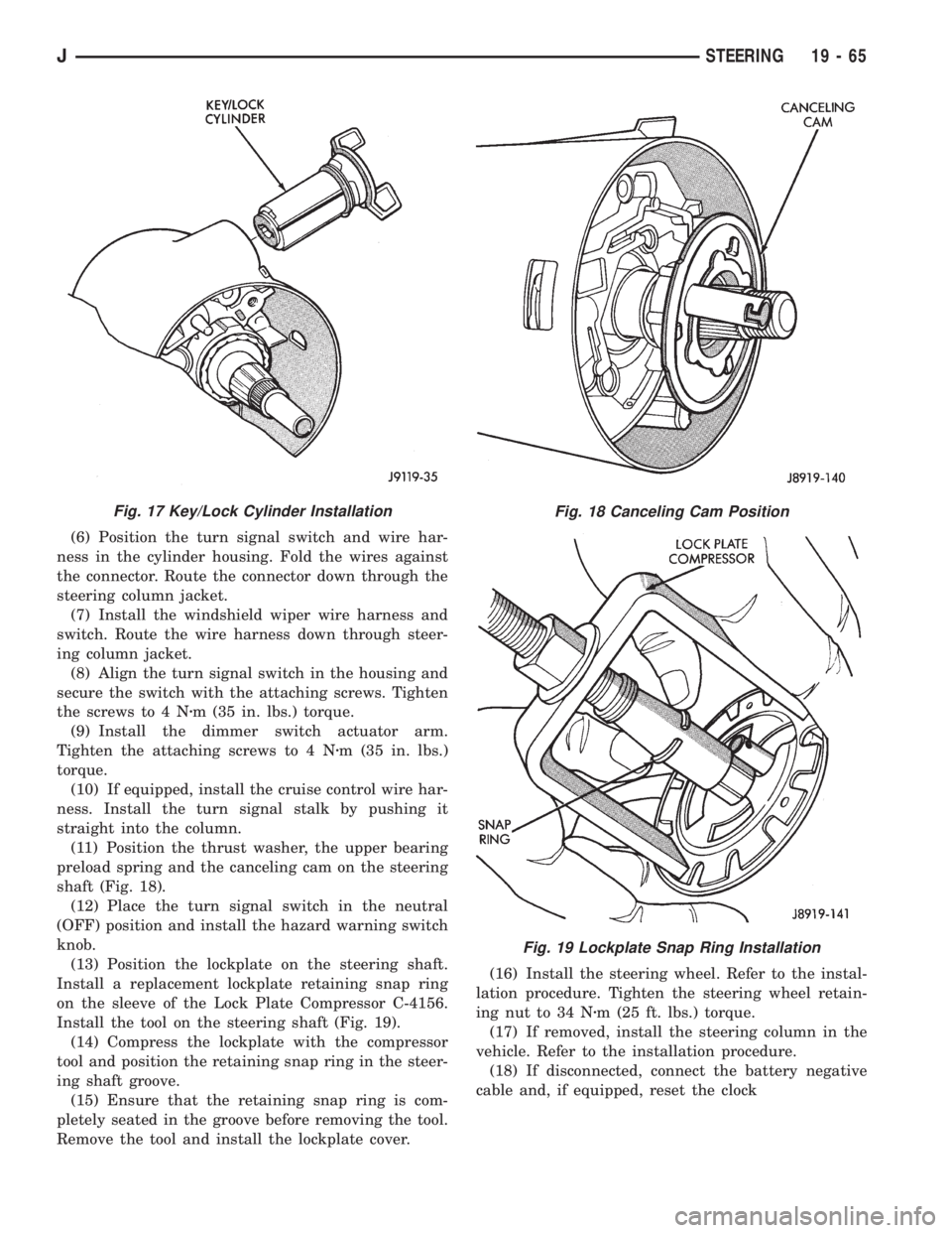
(6) Position the turn signal switch and wire har-
ness in the cylinder housing. Fold the wires against
the connector. Route the connector down through the
steering column jacket.
(7) Install the windshield wiper wire harness and
switch. Route the wire harness down through steer-
ing column jacket.
(8) Align the turn signal switch in the housing and
secure the switch with the attaching screws. Tighten
the screws to 4 Nzm (35 in. lbs.) torque.
(9) Install the dimmer switch actuator arm.
Tighten the attaching screws to 4 Nzm (35 in. lbs.)
torque.
(10) If equipped, install the cruise control wire har-
ness. Install the turn signal stalk by pushing it
straight into the column.
(11) Position the thrust washer, the upper bearing
preload spring and the canceling cam on the steering
shaft (Fig. 18).
(12) Place the turn signal switch in the neutral
(OFF) position and install the hazard warning switch
knob.
(13) Position the lockplate on the steering shaft.
Install a replacement lockplate retaining snap ring
on the sleeve of the Lock Plate Compressor C-4156.
Install the tool on the steering shaft (Fig. 19).
(14) Compress the lockplate with the compressor
tool and position the retaining snap ring in the steer-
ing shaft groove.
(15) Ensure that the retaining snap ring is com-
pletely seated in the groove before removing the tool.
Remove the tool and install the lockplate cover.(16) Install the steering wheel. Refer to the instal-
lation procedure. Tighten the steering wheel retain-
ing nut to 34 Nzm (25 ft. lbs.) torque.
(17) If removed, install the steering column in the
vehicle. Refer to the installation procedure.
(18) If disconnected, connect the battery negative
cable and, if equipped, reset the clock
Fig. 17 Key/Lock Cylinder InstallationFig. 18 Canceling Cam Position
Fig. 19 Lockplate Snap Ring Installation
JSTEERING 19 - 65
Page 1550 of 2158
TILT STEERING COLUMN
DISASSEMBLY
(1) Remove the steering column from the vehicle, if
necessary. Refer to the removal procedure.
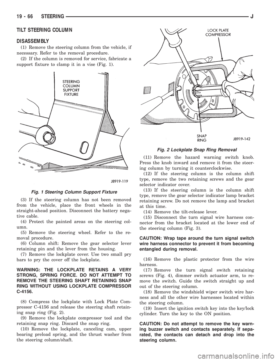
(2) If the column is removed for service, fabricate a
support fixture to clamp it in a vise (Fig. 1).
(3) If the steering column has not been removed
from the vehicle, place the front wheels in the
straight-ahead position. Disconnect the battery nega-
tive cable.
(4) Protect the painted areas on the steering col-
umn.
(5) Remove the steering wheel. Refer to the re-
moval procedure.
(6) Column shift: Remove the gear selector lever
retaining pin and the lever from the housing.
(7) Remove the lockplate cover. Use two small pry
bars to pry the cover off the lockplate.
WARNING: THE LOCKPLATE RETAINS A VERY
STRONG, SPRING FORCE. DO NOT ATTEMPT TO
REMOVE THE STEERING SHAFT RETAINING SNAP
RING WITHOUT USING LOCKPLATE COMPRESSOR
C-4156.
(8) Compress the lockplate with Lock Plate Com-
pressor C-4156 and release the steering shaft retain-
ing snap ring (Fig. 2).
(9) Remove the lockplate compressor tool and the
retaining snap ring. Discard the snap ring.
(10) Remove the lockplate, canceling cam, upper
bearing preload spring, and the thrust washer from
the steering column/shaft.(11) Remove the hazard warning switch knob.
Press the knob inward and remove it from the steer-
ing column by turning it counterclockwise.
(12) If the steering column is the column shift
type, remove the two retaining screws and the gear
selector indicator cover.
(13) If the steering column is the column shift
type, remove the gear selector indicator lamp bracket
retaining screw. Do not remove the lamp and bracket
at this time.
(14) Remove the tilt-release lever.
(15) Disconnect the turn signal wire harness con-
nector from the bracket located at the lower end of
the steering column (Fig. 3).
CAUTION: Wrap tape around the turn signal switch
wire harness connector to prevent it from becoming
entangled during removal.
(16) Remove the plastic protector from the wire
harness.
(17) Remove the turn signal switch retaining
screws (Fig. 4), dimmer switch actuator arm, to re-
move the switch. Guide the switch straight up and
out of the steering column.
(18) Remove the windshield wiper switch wire har-
ness and all the other wire harnesses located within
the steering column.
(19) Insert the ignition switch key into the key/lock
cylinder. Turn the key to the ON position.
CAUTION: Do not attempt to remove the key warn-
ing buzzer switch and contacts separately. If sepa-
rated, the contacts can detach and drop into the
steering column.
Fig. 1 Steering Column Support Fixture
Fig. 2 Lockplate Snap Ring Removal
19 - 66 STEERINGJ
Page 1921 of 2158
EXTERIOR COMPONENTS
INDEX
page page
Air Exhaust GrilleÐXJ...................... 25
Battery TrayÐXJ.......................... 14
Body Side Molding/CladdingÐXJ.............. 20
Body Stripes/DecalsÐXJ.................... 21
Brush GuardÐXJ.......................... 3
Cowl Grille and ScreenÐXJ................. 12
Cowl Weatherstrip Seal/Crossmember Air
DeflectorÐXJ........................... 11
Dash Panel Insulator PanelÐXJ.............. 12
Drip Rail MoldingÐXJ...................... 25
Exterior NameplatesÐXJ................... 26
External MirrorsÐXJ....................... 27
Front FenderÐXJ......................... 14
Fuel Filler Door BumpersÐXJ................ 27Fuel Filler Nozzle/TubeÐXJ................. 26
Grille and Grille Opening Panel (GOP)ÐXJ....... 3
Hood AdjustmentÐXJ...................... 10
Hood Hinge ReplacementÐXJ............... 10
Hood Latch ReplacementÐXJ................ 11
Hood Latch Striker ReplacementÐXJ.......... 11
HoodÐXJ................................ 7
Latch Release Cable ReplacementÐXJ......... 11
Luggage RackÐXJ........................ 28
Quarter Window AppliqueÐXJ................ 25
Radiator Support CrossmemberÐXJ............ 6
Rear Wheelhouse Flares and LinersÐXJ........ 19
Safety Latch Striker ReplacementÐXJ.......... 11
BRUSH GUARDÐXJ
REMOVAL
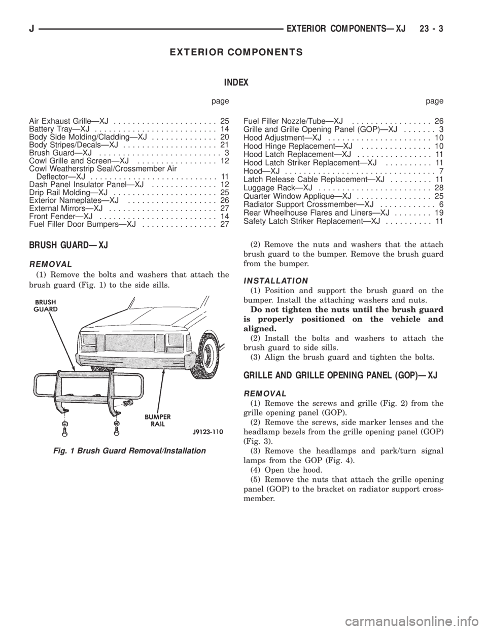
(1) Remove the bolts and washers that attach the
brush guard (Fig. 1) to the side sills.(2) Remove the nuts and washers that the attach
brush guard to the bumper. Remove the brush guard
from the bumper.INSTALLATION
(1) Position and support the brush guard on the
bumper. Install the attaching washers and nuts.
Do not tighten the nuts until the brush guard
is properly positioned on the vehicle and
aligned.
(2) Install the bolts and washers to attach the
brush guard to side sills.
(3) Align the brush guard and tighten the bolts.
GRILLE AND GRILLE OPENING PANEL (GOP)ÐXJ
REMOVAL
(1) Remove the screws and grille (Fig. 2) from the
grille opening panel (GOP).
(2) Remove the screws, side marker lenses and the
headlamp bezels from the grille opening panel (GOP)
(Fig. 3).
(3) Remove the headlamps and park/turn signal
lamps from the GOP (Fig. 4).
(4) Open the hood.
(5) Remove the nuts that attach the grille opening
panel (GOP) to the bracket on radiator support cross-
member.
Fig. 1 Brush Guard Removal/Installation
JEXTERIOR COMPONENTSÐXJ 23 - 3
Page 1932 of 2158
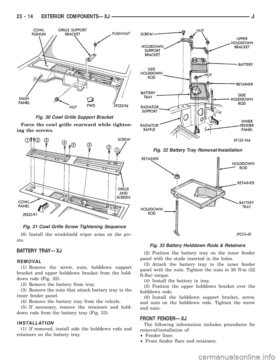
Force the cowl grille rearward while tighten-
ing the screws.
(6) Install the windshield wiper arms on the piv-
ots.
BATTERY TRAYÐXJ
REMOVAL
(1) Remove the screw, nuts, holddown support
bracket and upper holddown bracket from the hold-
down rods (Fig. 32).
(2) Remove the battery from tray.
(3) Remove the nuts that attach battery tray to the
inner fender panel.
(4) Remove the battery tray from the vehicle.
(5) If necessary, remove the retainers and hold-
down rods from the battery tray (Fig. 33).
INSTALLATION
(1) If removed, install side the holddown rods and
retainers on the battery tray.(2) Position the battery tray on the inner fender
panel with the studs inserted in the holes.
(3) Attach the battery tray to the inner fender
panel with the nuts. Tighten the nuts to 30 Nzm (22
ft-lbs) torque.
(4) Install the battery in tray.
(5) Position the upper holddown bracket over the
holddown rods.
(6) Install the holddown support bracket, screw,
and nuts on the holddown rods. Tighten the screw
and nuts.
FRONT FENDERÐXJ
The following information includes procedures for
removal/installation of:
²Fender liner.
²Front fender flare and retainers.
Fig. 30 Cowl Grille Support Bracket
Fig. 31 Cowl Grille Screw Tightening Sequence
Fig. 32 Battery Tray Removal/Installation
Fig. 33 Battery Holddown Rods & Retainers
23 - 14 EXTERIOR COMPONENTSÐXJJ
Page 1933 of 2158
²Front fender.
REMOVAL
(1) Remove the front bumper.
(2) Right fender only:
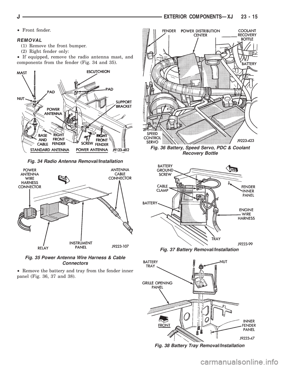
²If equipped, remove the radio antenna mast, and
components from the fender (Fig. 34 and 35).
²Remove the battery and tray from the fender inner
panel (Fig. 36, 37 and 38).
Fig. 36 Battery, Speed Servo, PDC & Coolant
Recovery Bottle
Fig. 37 Battery Removal/Installation
Fig. 38 Battery Tray Removal/Installation
Fig. 34 Radio Antenna Removal/Installation
Fig. 35 Power Antenna Wire Harness & Cable
Connectors
JEXTERIOR COMPONENTSÐXJ 23 - 15
Page 1937 of 2158
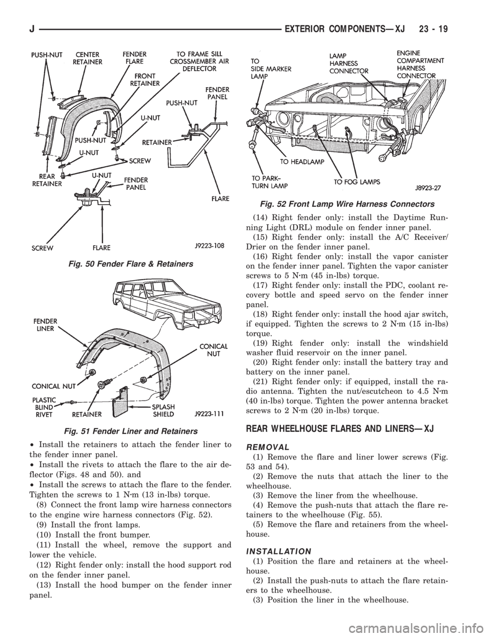
²Install the retainers to attach the fender liner to
the fender inner panel.
²Install the rivets to attach the flare to the air de-
flector (Figs. 48 and 50). and
²Install the screws to attach the flare to the fender.
Tighten the screws to 1 Nzm (13 in-lbs) torque.
(8) Connect the front lamp wire harness connectors
to the engine wire harness connectors (Fig. 52).
(9) Install the front lamps.
(10) Install the front bumper.
(11) Install the wheel, remove the support and
lower the vehicle.
(12) Right fender only: install the hood support rod
on the fender inner panel.
(13) Install the hood bumper on the fender inner
panel.(14) Right fender only: install the Daytime Run-
ning Light (DRL) module on fender inner panel.
(15) Right fender only: install the A/C Receiver/
Drier on the fender inner panel.
(16) Right fender only: install the vapor canister
on the fender inner panel. Tighten the vapor canister
screws to 5 Nzm (45 in-lbs) torque.
(17) Right fender only: install the PDC, coolant re-
covery bottle and speed servo on the fender inner
panel.
(18) Right fender only: install the hood ajar switch,
if equipped. Tighten the screws to 2 Nzm (15 in-lbs)
torque.
(19) Right fender only: install the windshield
washer fluid reservoir on the inner panel.
(20) Right fender only: install the battery tray and
battery on the inner panel.
(21) Right fender only: if equipped, install the ra-
dio antenna. Tighten the nut/escutcheon to 4.5 Nzm
(40 in-lbs) torque. Tighten the power antenna bracket
screws to 2 Nzm (20 in-lbs) torque.
REAR WHEELHOUSE FLARES AND LINERSÐXJ
REMOVAL
(1) Remove the flare and liner lower screws (Fig.
53 and 54).
(2) Remove the nuts that attach the liner to the
wheelhouse.
(3) Remove the liner from the wheelhouse.
(4) Remove the push-nuts that attach the flare re-
tainers to the wheelhouse (Fig. 55).
(5) Remove the flare and retainers from the wheel-
house.
INSTALLATION
(1) Position the flare and retainers at the wheel-
house.
(2) Install the push-nuts to attach the flare retain-
ers to the wheelhouse.
(3) Position the liner in the wheelhouse.
Fig. 50 Fender Flare & Retainers
Fig. 51 Fender Liner and Retainers
Fig. 52 Front Lamp Wire Harness Connectors
JEXTERIOR COMPONENTSÐXJ 23 - 19
Page 1995 of 2158
TRAILER HITCH
TRAILER HITCHÐXJ
CLASS III HITCH
A class III weight-distributing/equalizer type hitch
can be used to tow a trailer:
²Having a maximum gross weight of 5,000 lbs/2250
kg.
²Having a maximum tongue weight of 750 lbs/332
kg).
The following vehicle basic equipment is required
for class III trailer towing:
²P205/75R15 or larger tires.
²Full size spare tire.
²Trailer sway control.
²Trailer tow wire harness and connector.
²Heavy duty turn signal flasher element.
²Heavy duty axle (with synthetic lubricant).
²Heavy duty cooling system.
²Heavy duty generator/battery.
²Auxiliary automatic transmission fluid cooler.
²I-6, 4.0L engine.
Wide-angle type door mirrors are recommended but
not required.
WIRE HARNESS CONNECTORS
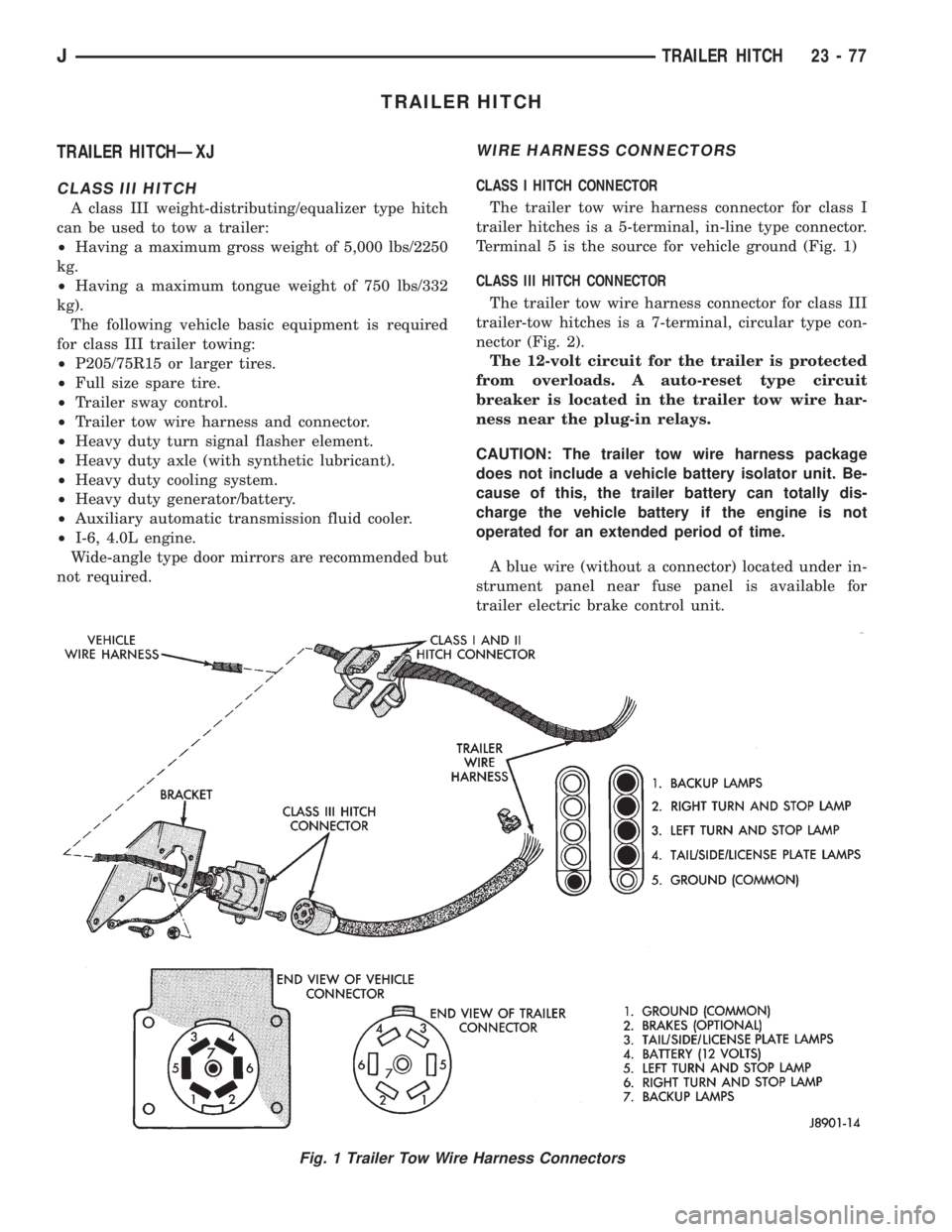
CLASS I HITCH CONNECTOR
The trailer tow wire harness connector for class I
trailer hitches is a 5-terminal, in-line type connector.
Terminal 5 is the source for vehicle ground (Fig. 1)
CLASS III HITCH CONNECTOR
The trailer tow wire harness connector for class III
trailer-tow hitches is a 7-terminal, circular type con-
nector (Fig. 2).
The 12-volt circuit for the trailer is protected
from overloads. A auto-reset type circuit
breaker is located in the trailer tow wire har-
ness near the plug-in relays.
CAUTION: The trailer tow wire harness package
does not include a vehicle battery isolator unit. Be-
cause of this, the trailer battery can totally dis-
charge the vehicle battery if the engine is not
operated for an extended period of time.
A blue wire (without a connector) located under in-
strument panel near fuse panel is available for
trailer electric brake control unit.
Fig. 1 Trailer Tow Wire Harness Connectors
JTRAILER HITCH 23 - 77
Page 2012 of 2158
INSTALLATION
(1) Install the support bracket and the retaining
screw. Tighten the screw to 1 Nzm (9 in-lbs) torque.
(2) Position the sunvisor in the support clip and
align the arm support bracket holes with the head-
liner holes.
(3) Install the screws that attach the sunvisor arm
support bracket to the headliner and the roof panel.
Tighten the screws to 4 Nzm (35 in-lbs) torque.
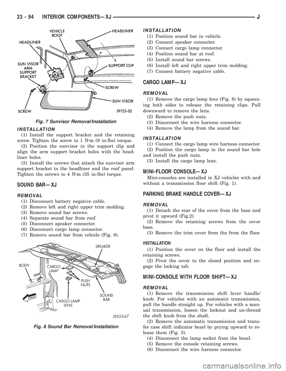
SOUND BARÐXJ
REMOVAL
(1) Disconnect battery negative cable.
(2) Remove left and right upper trim molding.
(3) Remove sound bar screws.
(4) Separate sound bar from roof.
(5) Disconnect speaker connector.
(6) Disconnect cargo lamp connector.
(7) Remove sound bar from vehicle (Fig. 8).
INSTALLATION
(1) Position sound bar in vehicle.
(2) Connect speaker connecter.
(3) Connect cargo lamp connector.
(4) Position sound bar at roof.
(5) Install sound bar screws.
(6) Install left and right upper trim molding.
(7) Connect battery negative cable.
CARGO LAMPÐXJ
REMOVAL
(1) Remove the cargo lamp lens (Fig. 8) by squeez-
ing both sides to release the retaining clips. Pull
downward to remove the lens.
(2) Remove the push nuts.
(3) Disconnect the wire harness connector.
(4) Remove the lamp from the sound bar.
INSTALLATION
(1) Connect the cargo lamp wire harness connector.
(2) Position the cargo lamp in the sound bar hole
and install the push nuts.
(3) Install the cargo lamp lens.
MINI-FLOOR CONSOLEÐXJ
Mini-consoles are installed in XJ vehicles with and
without a transmission floor shift (Fig. 1).
PARKING BRAKE HANDLE COVERÐXJ
REMOVAL
(1) Detach the rear of the cover from the base and
pivot it upward (Fig.2).
(2) Remove the retaining screws from the cover
base.
(3) Remove the trim cover from the from the floor.
INSTALLATION
(1) Position the cover on the floor and install the
retaining screws.
(2) Pivot the cover to the closed position and en-
gage the locking tab.
MINI-CONSOLE WITH FLOOR SHIFTÐXJ
REMOVAL
(1) Remove the transmission shift lever handle/
knob. For vehicles with an automatic transmission,
pull the handle straight up. For vehicles with a man-
ual transmission, loosen the locknut and un-thread
the shift knob from the shaft.
(2) Remove the automatic transmission and trans-
fer case shift indicator bezel by prying upward to re-
lease them (Fig. 3).
(4) Disconnect the lamp socket from the bezel.
(5) Remove the console retaining screws.
(6) Disconnect the wire harness connector.
Fig. 7 Sunvisor Removal/Installation
Fig. 8 Sound Bar Removal/Installation
23 - 94 INTERIOR COMPONENTSÐXJJ