1995 JEEP YJ air filter
[x] Cancel search: air filterPage 49 of 2158
FLUID LEVEL
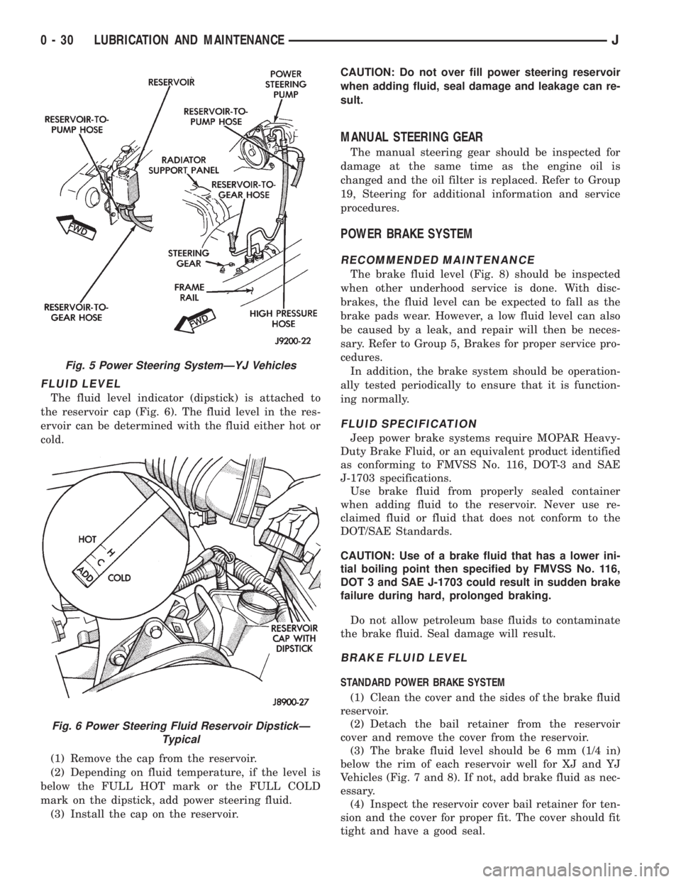
The fluid level indicator (dipstick) is attached to
the reservoir cap (Fig. 6). The fluid level in the res-
ervoir can be determined with the fluid either hot or
cold.
(1) Remove the cap from the reservoir.
(2) Depending on fluid temperature, if the level is
below the FULL HOT mark or the FULL COLD
mark on the dipstick, add power steering fluid.
(3) Install the cap on the reservoir.CAUTION: Do not over fill power steering reservoir
when adding fluid, seal damage and leakage can re-
sult.
MANUAL STEERING GEAR
The manual steering gear should be inspected for
damage at the same time as the engine oil is
changed and the oil filter is replaced. Refer to Group
19, Steering for additional information and service
procedures.
POWER BRAKE SYSTEM
RECOMMENDED MAINTENANCE
The brake fluid level (Fig. 8) should be inspected
when other underhood service is done. With disc-
brakes, the fluid level can be expected to fall as the
brake pads wear. However, a low fluid level can also
be caused by a leak, and repair will then be neces-
sary. Refer to Group 5, Brakes for proper service pro-
cedures.
In addition, the brake system should be operation-
ally tested periodically to ensure that it is function-
ing normally.
FLUID SPECIFICATION
Jeep power brake systems require MOPAR Heavy-
Duty Brake Fluid, or an equivalent product identified
as conforming to FMVSS No. 116, DOT-3 and SAE
J-1703 specifications.
Use brake fluid from properly sealed container
when adding fluid to the reservoir. Never use re-
claimed fluid or fluid that does not conform to the
DOT/SAE Standards.
CAUTION: Use of a brake fluid that has a lower ini-
tial boiling point then specified by FMVSS No. 116,
DOT 3 and SAE J-1703 could result in sudden brake
failure during hard, prolonged braking.
Do not allow petroleum base fluids to contaminate
the brake fluid. Seal damage will result.
BRAKE FLUID LEVEL
STANDARD POWER BRAKE SYSTEM
(1) Clean the cover and the sides of the brake fluid
reservoir.
(2) Detach the bail retainer from the reservoir
cover and remove the cover from the reservoir.
(3) The brake fluid level should be 6 mm (1/4 in)
below the rim of each reservoir well for XJ and YJ
Vehicles (Fig. 7 and 8). If not, add brake fluid as nec-
essary.
(4) Inspect the reservoir cover bail retainer for ten-
sion and the cover for proper fit. The cover should fit
tight and have a good seal.
Fig. 5 Power Steering SystemÐYJ Vehicles
Fig. 6 Power Steering Fluid Reservoir DipstickÐ
Typical
0 - 30 LUBRICATION AND MAINTENANCEJ
Page 51 of 2158

(2) Note any indication of drum/rotor overheating,
wheel dragging or the vehicle pulling to one side
when the brakes are applied.
(3) Evaluate any performance complaints received
from the owner/operator.
(4) Repair the brake system as necessary. Refer to
Group, 5 Brakes for additional information and ser-
vice procedures.
TIRES
RECOMMENDED MAINTENANCE
The general condition of the tires and the inflation
pressures should be inspected at the same time the
engine oil is changed and the oil filter is replaced.
In addition, the tires/wheels should be rotated at
the intervals described in the Maintenance Schedules
section of this group.
INSPECTION
Inspect the tires for excessive wear, damage, etc.
Test the tires for the recommended inflation pres-sure. Refer to the tire inflation pressure decal located
on the inside of the glove box door, and also to Group
22, Tires And Wheels.
ROTATION
Refer to Group 22, Tires And Wheels for the recom-
mended method of tire/wheel rotation for a Jeep ve-
hicle.
BODY COMPONENTS
LUBRICATION REQUIREMENTS
All Jeep operating mechanisms and linkages
should be lubricated when necessary. The door
weatherstrip seals should be lubricated to prolong
their life as well as to improve door sealing.
LUBRICANT SPECIFICATIONS
All applicable exterior and interior vehicle operat-
ing mechanisms should be:
²Inspected
²Cleaned
²Pivot/sliding contact areas on the mechanisms
should then be lubricated.
Multi-purpose NLGI GC-LB MOPAR Multi-Mileage
Lubricant or an equivalent, should be used to lubri-
cate the mechanisms. The door weatherstrip seals
should be lubricated with silicone lubricant spray.
Refer to the Body Lubricant Specifications chart be-
low for additional lubricant applications.
LUBRICATION
All pivoting and sliding contact areas, should be lu-
bricated periodically to ensure quiet, easy operation
and to protect against wear and corrosion. Areas in-
clude:
²Seat tracks.
²Door hinges/latches/strikers.
²Liftgate/tailgate/hood hinges (Fig. 11).
(1) As required, lubricate the body components
with the specified lubricants.
(2) Apply silicone lubricant to a cloth and wipe it
on door seals to avoid over-spray that can soil pas-
senger clothing.
(3) Before applying lubricant, the component
should be wiped clean. After lubrication, any excess
lubricant should be removed.
(4) The door lock cylinders should be lubricated 2
times each year (preferably autumn and spring):
²Spray a small amount of lock cylinder lubricant di-
rectly into the lock cylinder.
²Apply a small amount to the key and insert it into
the lock cylinder.
²Rotate it to the locked position and then back to
the unlocked position several times.
²Remove the key. Wipe the lubricant from it with a
clean cloth to avoid soiling of clothing.
Fig. 9 Park Brake Equalizer (XJ)ÐTypical
Fig. 10 Park Brake Equalizer (YJ)ÐTypical
0 - 32 LUBRICATION AND MAINTENANCEJ
Page 79 of 2158
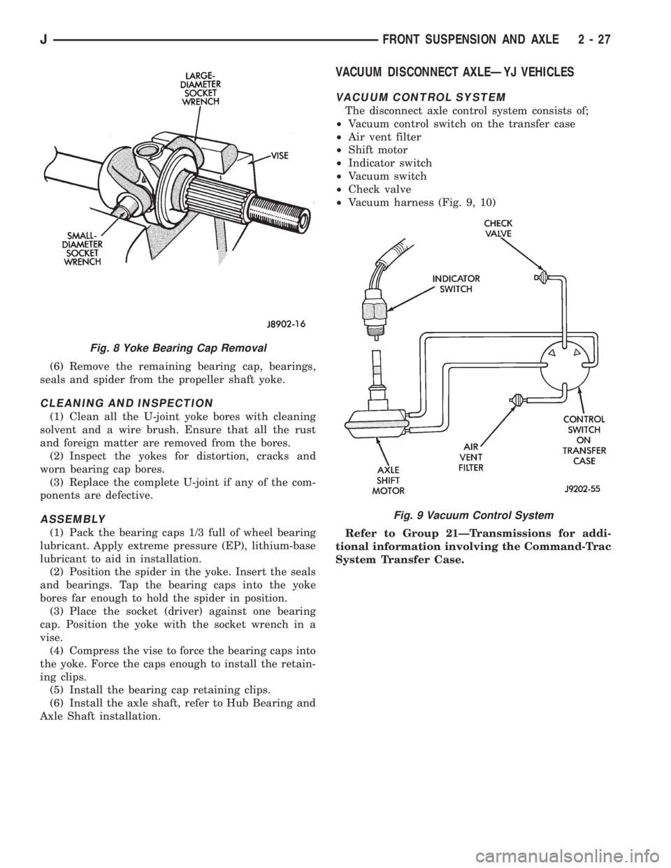
(6) Remove the remaining bearing cap, bearings,
seals and spider from the propeller shaft yoke.
CLEANING AND INSPECTION
(1) Clean all the U-joint yoke bores with cleaning
solvent and a wire brush. Ensure that all the rust
and foreign matter are removed from the bores.
(2) Inspect the yokes for distortion, cracks and
worn bearing cap bores.
(3) Replace the complete U-joint if any of the com-
ponents are defective.
ASSEMBLY
(1) Pack the bearing caps 1/3 full of wheel bearing
lubricant. Apply extreme pressure (EP), lithium-base
lubricant to aid in installation.
(2) Position the spider in the yoke. Insert the seals
and bearings. Tap the bearing caps into the yoke
bores far enough to hold the spider in position.
(3) Place the socket (driver) against one bearing
cap. Position the yoke with the socket wrench in a
vise.
(4) Compress the vise to force the bearing caps into
the yoke. Force the caps enough to install the retain-
ing clips.
(5) Install the bearing cap retaining clips.
(6) Install the axle shaft, refer to Hub Bearing and
Axle Shaft installation.
VACUUM DISCONNECT AXLEÐYJ VEHICLES
VACUUM CONTROL SYSTEM
The disconnect axle control system consists of;
²Vacuum control switch on the transfer case
²Air vent filter
²Shift motor
²Indicator switch
²Vacuum switch
²Check valve
²Vacuum harness (Fig. 9, 10)
Refer to Group 21ÐTransmissions for addi-
tional information involving the Command-Trac
System Transfer Case.
Fig. 8 Yoke Bearing Cap Removal
Fig. 9 Vacuum Control System
JFRONT SUSPENSION AND AXLE 2 - 27
Page 169 of 2158
the bore surface is normal and acceptable but only if
the surface is in good condition.
Replace the cylinder if the bore is scored, corroded,
or pitted.Do not hone the cylinder bore in an at-
tempt to restore the surface. Replace the cylin-
der if the bore is corroded or if doubt exists
about cylinder bore condition.
Check the outer and inner surfaces of the cylinder
for cracks or porosity, especially if wet spots were
noted on the cylinder outer surface during removal
and disassembly.
Inspect the cylinder cover, seal and retainer spring.
Replace the seal if torn or distorted and replace the
cover and spring if either part is bent or damaged in
any way.
MASTER CYLINDER ASSEMBLY
(1) Coat cylinder bore and new piston assemblies
with brake fluid.
(2) Install secondary piston in bore with push and
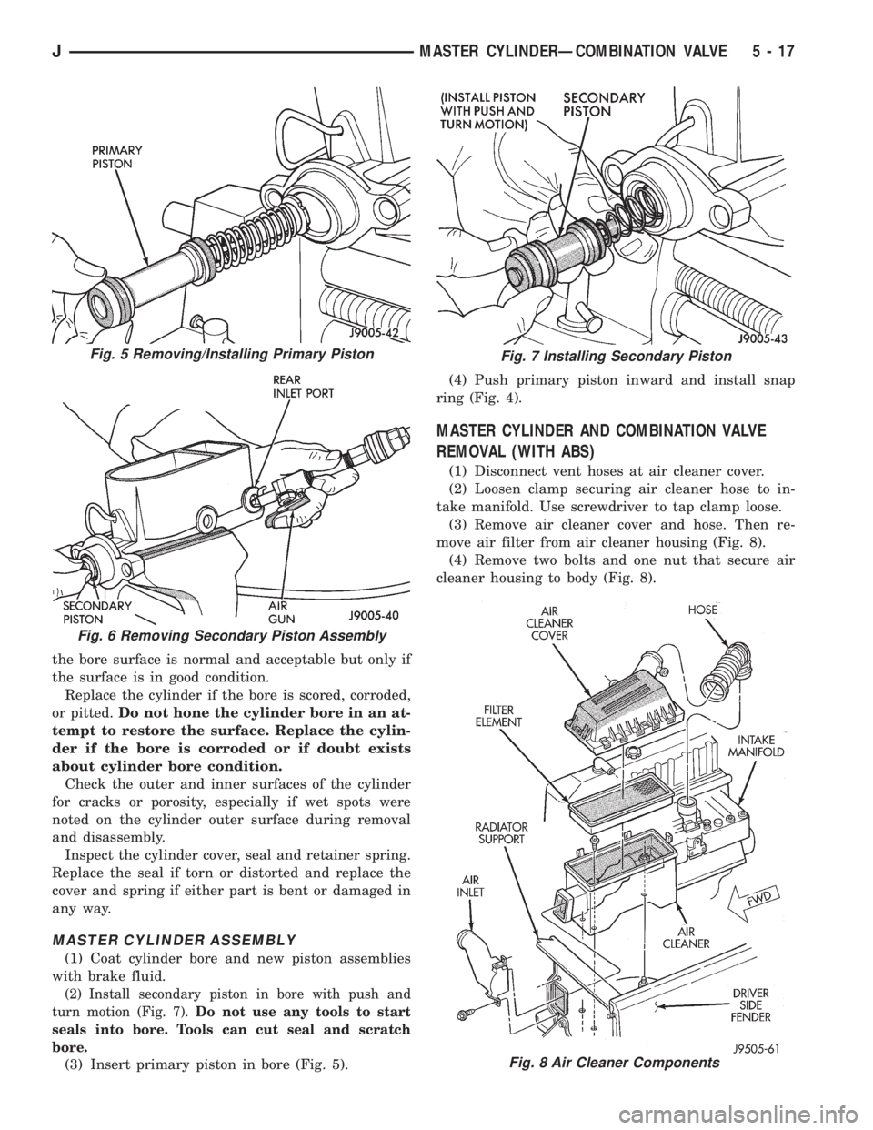
turn motion (Fig. 7).Do not use any tools to start
seals into bore. Tools can cut seal and scratch
bore.
(3) Insert primary piston in bore (Fig. 5).(4) Push primary piston inward and install snap
ring (Fig. 4).
MASTER CYLINDER AND COMBINATION VALVE
REMOVAL (WITH ABS)
(1) Disconnect vent hoses at air cleaner cover.
(2) Loosen clamp securing air cleaner hose to in-
take manifold. Use screwdriver to tap clamp loose.
(3) Remove air cleaner cover and hose. Then re-
move air filter from air cleaner housing (Fig. 8).
(4) Remove two bolts and one nut that secure air
cleaner housing to body (Fig. 8).
Fig. 8 Air Cleaner Components
Fig. 5 Removing/Installing Primary Piston
Fig. 6 Removing Secondary Piston Assembly
Fig. 7 Installing Secondary Piston
JMASTER CYLINDERÐCOMBINATION VALVE 5 - 17
Page 173 of 2158
(7) Install combination valve as follows:
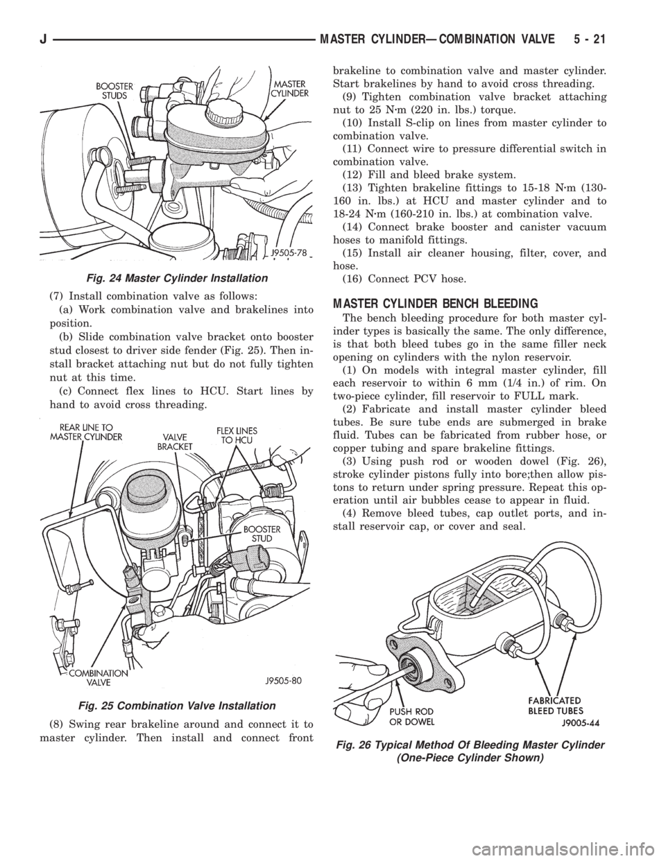
(a) Work combination valve and brakelines into
position.
(b) Slide combination valve bracket onto booster
stud closest to driver side fender (Fig. 25). Then in-
stall bracket attaching nut but do not fully tighten
nut at this time.
(c) Connect flex lines to HCU. Start lines by
hand to avoid cross threading.
(8) Swing rear brakeline around and connect it to
master cylinder. Then install and connect frontbrakeline to combination valve and master cylinder.
Start brakelines by hand to avoid cross threading.
(9) Tighten combination valve bracket attaching
nut to 25 Nzm (220 in. lbs.) torque.
(10) Install S-clip on lines from master cylinder to
combination valve.
(11) Connect wire to pressure differential switch in
combination valve.
(12) Fill and bleed brake system.
(13) Tighten brakeline fittings to 15-18 Nzm (130-
160 in. lbs.) at HCU and master cylinder and to
18-24 Nzm (160-210 in. lbs.) at combination valve.
(14) Connect brake booster and canister vacuum
hoses to manifold fittings.
(15) Install air cleaner housing, filter, cover, and
hose.
(16) Connect PCV hose.MASTER CYLINDER BENCH BLEEDING
The bench bleeding procedure for both master cyl-
inder types is basically the same. The only difference,
is that both bleed tubes go in the same filler neck
opening on cylinders with the nylon reservoir.
(1) On models with integral master cylinder, fill
each reservoir to within 6 mm (1/4 in.) of rim. On
two-piece cylinder, fill reservoir to FULL mark.
(2) Fabricate and install master cylinder bleed
tubes. Be sure tube ends are submerged in brake
fluid. Tubes can be fabricated from rubber hose, or
copper tubing and spare brakeline fittings.
(3) Using push rod or wooden dowel (Fig. 26),
stroke cylinder pistons fully into bore;then allow pis-
tons to return under spring pressure. Repeat this op-
eration until air bubbles cease to appear in fluid.
(4) Remove bleed tubes, cap outlet ports, and in-
stall reservoir cap, or cover and seal.
Fig. 24 Master Cylinder Installation
Fig. 25 Combination Valve Installation
Fig. 26 Typical Method Of Bleeding Master Cylinder
(One-Piece Cylinder Shown)
JMASTER CYLINDERÐCOMBINATION VALVE 5 - 21
Page 176 of 2158
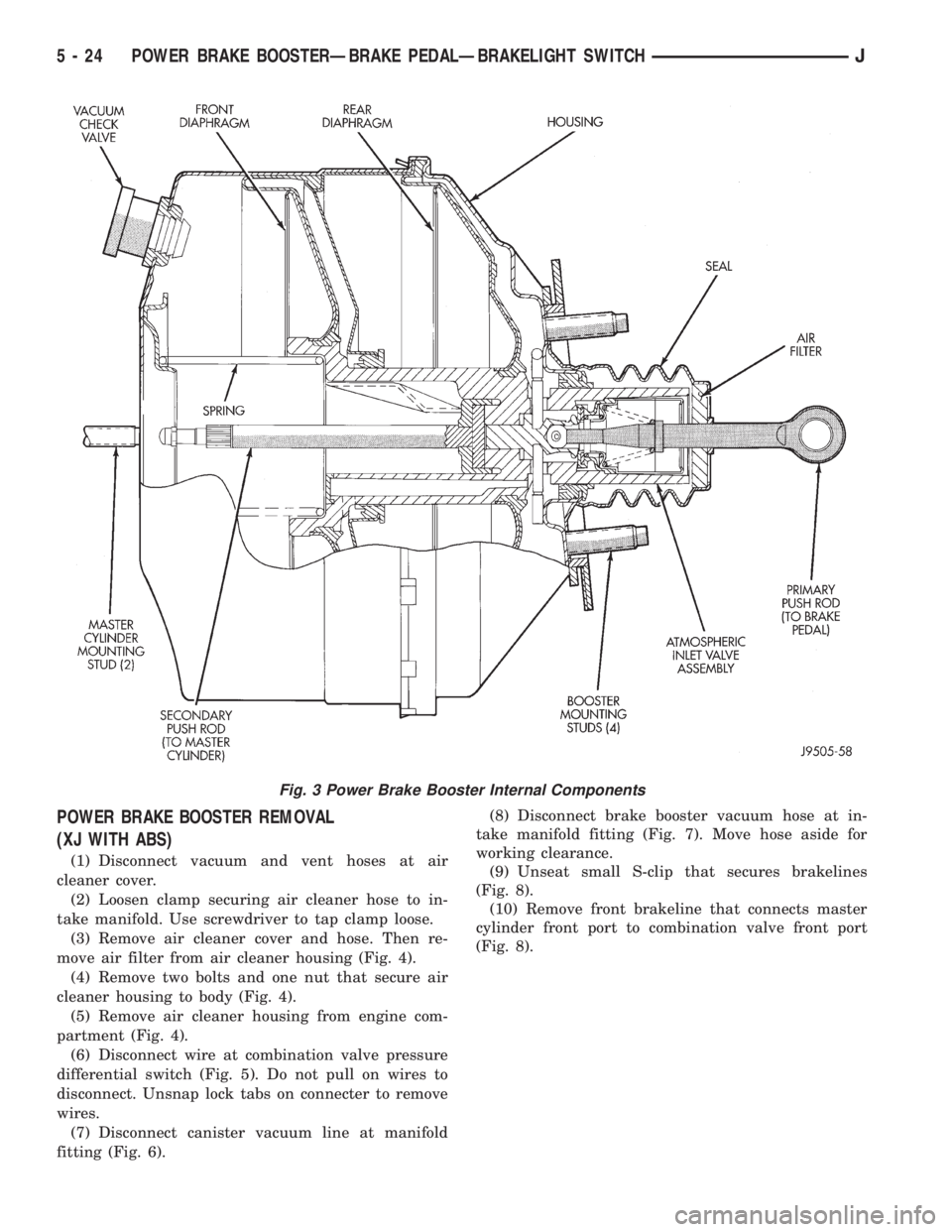
POWER BRAKE BOOSTER REMOVAL
(XJ WITH ABS)
(1) Disconnect vacuum and vent hoses at air
cleaner cover.
(2) Loosen clamp securing air cleaner hose to in-
take manifold. Use screwdriver to tap clamp loose.
(3) Remove air cleaner cover and hose. Then re-
move air filter from air cleaner housing (Fig. 4).
(4) Remove two bolts and one nut that secure air
cleaner housing to body (Fig. 4).
(5) Remove air cleaner housing from engine com-
partment (Fig. 4).
(6) Disconnect wire at combination valve pressure
differential switch (Fig. 5). Do not pull on wires to
disconnect. Unsnap lock tabs on connecter to remove
wires.
(7) Disconnect canister vacuum line at manifold
fitting (Fig. 6).(8) Disconnect brake booster vacuum hose at in-
take manifold fitting (Fig. 7). Move hose aside for
working clearance.
(9) Unseat small S-clip that secures brakelines
(Fig. 8).
(10) Remove front brakeline that connects master
cylinder front port to combination valve front port
(Fig. 8).
Fig. 3 Power Brake Booster Internal Components
5 - 24 POWER BRAKE BOOSTERÐBRAKE PEDALÐBRAKELIGHT SWITCHJ
Page 181 of 2158
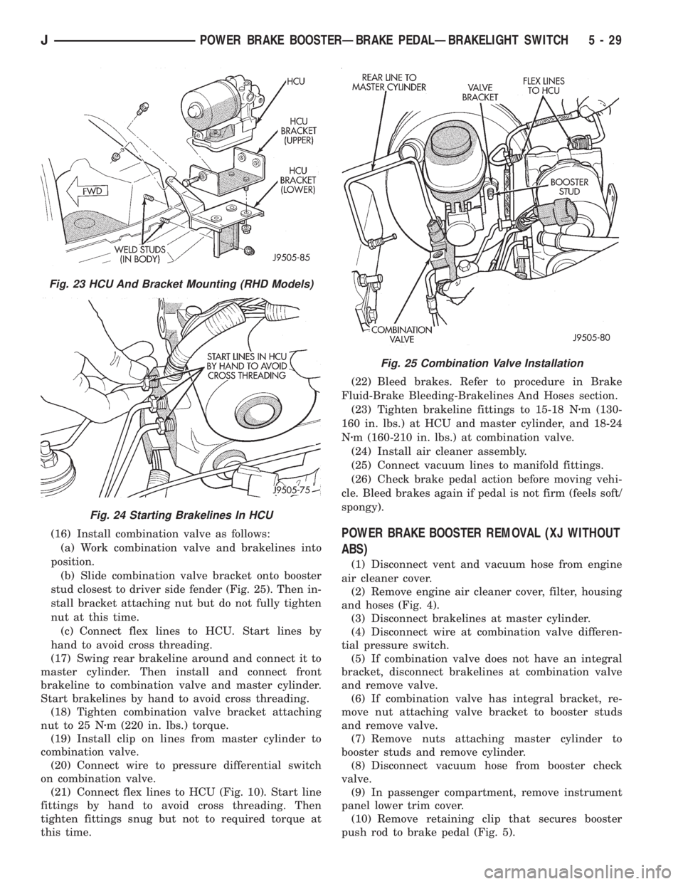
(16) Install combination valve as follows:
(a) Work combination valve and brakelines into
position.
(b) Slide combination valve bracket onto booster
stud closest to driver side fender (Fig. 25). Then in-
stall bracket attaching nut but do not fully tighten
nut at this time.
(c) Connect flex lines to HCU. Start lines by
hand to avoid cross threading.
(17) Swing rear brakeline around and connect it to
master cylinder. Then install and connect front
brakeline to combination valve and master cylinder.
Start brakelines by hand to avoid cross threading.
(18) Tighten combination valve bracket attaching
nut to 25 Nzm (220 in. lbs.) torque.
(19) Install clip on lines from master cylinder to
combination valve.
(20) Connect wire to pressure differential switch
on combination valve.
(21) Connect flex lines to HCU (Fig. 10). Start line
fittings by hand to avoid cross threading. Then
tighten fittings snug but not to required torque at
this time.(22) Bleed brakes. Refer to procedure in Brake
Fluid-Brake Bleeding-Brakelines And Hoses section.
(23) Tighten brakeline fittings to 15-18 Nzm (130-
160 in. lbs.) at HCU and master cylinder, and 18-24
Nzm (160-210 in. lbs.) at combination valve.
(24) Install air cleaner assembly.
(25) Connect vacuum lines to manifold fittings.
(26) Check brake pedal action before moving vehi-
cle. Bleed brakes again if pedal is not firm (feels soft/
spongy).POWER BRAKE BOOSTER REMOVAL (XJ WITHOUT
ABS)
(1) Disconnect vent and vacuum hose from engine
air cleaner cover.
(2) Remove engine air cleaner cover, filter, housing
and hoses (Fig. 4).
(3) Disconnect brakelines at master cylinder.
(4) Disconnect wire at combination valve differen-
tial pressure switch.
(5) If combination valve does not have an integral
bracket, disconnect brakelines at combination valve
and remove valve.
(6) If combination valve has integral bracket, re-
move nut attaching valve bracket to booster studs
and remove valve.
(7) Remove nuts attaching master cylinder to
booster studs and remove cylinder.
(8) Disconnect vacuum hose from booster check
valve.
(9) In passenger compartment, remove instrument
panel lower trim cover.
(10) Remove retaining clip that secures booster
push rod to brake pedal (Fig. 5).
Fig. 23 HCU And Bracket Mounting (RHD Models)
Fig. 24 Starting Brakelines In HCU
Fig. 25 Combination Valve Installation
JPOWER BRAKE BOOSTERÐBRAKE PEDALÐBRAKELIGHT SWITCH 5 - 29
Page 193 of 2158

(2) Align and attach harness connector to ECU.
Slide connector into engagement with tangs on ECU.
Then tilt connector downward and into engagement
with ECU pin terminals. Exercise care as pin termi-
nals can be damaged if connector is forced into place.
(3) Connect harness to security alarm module, if
equipped.
(4) Position ECU bracket under instrument panel.
(5) Install and tighten ECU mounting bracket
bolts/nuts to 8-14 Nzm (75- 125 in. lbs.) torque.
(6) Install trim panel on instrument panel, if re-
moved.
ECU REMOVAL/INSTALLATION (YJ MODELS)
The antilock ECU is attached to the dash panel in-
side the passenger compartment. It is positioned just
above the heater/air conditioning plenum housing, in
line with the glove box (Fig. 16).
The ECU is attached to the dash panel by bolts
and nuts that are accessible from the engine com-
partment. The fasteners are located just to the right
of the battery.
On models with air conditioning, it will be neces-
sary to remove the air conditioning fascia panel and
ducts for access to the ECU and harness connecter.
HCU REMOVAL (XJ)
A new design HCU is used in 1995 models. The
new HCU has built-in accumulators that store the
extra fluid released for antilock mode operation. As a
result, the master cylinder and HCU are no longer
interconnected by hoses.The 1995 and prior hy-
draulic control units are NOT interchangeable.
(1) Disconnect vent hoses at air cleaner cover.
(2) Loosen clamp securing air cleaner hose to in-
take manifold. Use screwdriver to tap clamp loose.
(3) Remove air cleaner cover and hose. Then re-
move air filter from air cleaner shell (Fig. 17).
(4) Remove two bolts and one nut that secure air
cleaner housing to body panel (Fig. 17).
(5) Remove air cleaner housing from engine com-
partment.
Fig. 16 ECU Location (YJ)
Fig. 17 Air Cleaner Components
JABS OPERATION AND SERVICE 5 - 41