1995 JEEP YJ air filter
[x] Cancel search: air filterPage 1298 of 2158
(a) Disconnect the power steering hoses from the
fittings at the steering gear.
(b) Drain the pump reservoir.
(c) Cap the fittings on the hoses and steering
gear to prevent foreign material from entering the
system.
(21) Disconnect the coolant hoses from the rear of
the intake manifold.
(22) Identify, tag and disconnect all necessary wire
connectors and vacuum hoses.
(23) Raise the vehicle.
(24) Remove the oil filter.
(25) Remove the starter motor.
(26) Disconnect the exhaust pipe from the exhaust
manifold.
(27) Remove the flywheel and converter housing
access cover.
(28) If equipped with an automatic transmission,
mark the converter and drive plate location in refer-
ence to each other and remove the converter-to-drive
plate bolts.(29) Remove the upper flywheel and converter
housing bolts and loosen the bottom bolts.
(30) Remove the engine support cushion-to-engine
compartment bracket bolts.
(31) Remove the engine shock damper bracket
from the sill.
(32) Lower the vehicle.
(33) Attach a lifting device to the engine.
(34) Raise the engine slightly off the front sup-
ports.
(35) Place a support stand under the converter or
flywheel housing.
(36) Remove the remaining bottom converter or
flywheel housing bolts.
(37) Lift the engine out of the engine compartment
and install on an engine stand.
(38) Install the oil filter to keep foreign material
out of the engine.
INSTALLATION
(1) Remove the oil filter.
(2) Lift the engine off the stand and lower it into
the engine compartment. For easier installation, it
may be useful to remove the engine support cushions
from the engine support brackets as an aide for
alignment of the engine-to-transmission.
(3) If equipped with a manual transmission:
(a) Insert the transmission shaft into the clutch
spline.
(b) Align the flywheel housing with the engine.
(c) Install and tighten the flywheel housing lower
bolts finger tight.
(4) If equipped with an automatic transmission:
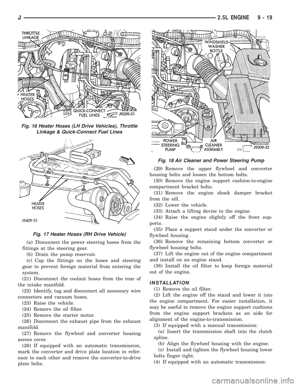
Fig. 16 Heater Hoses (LH Drive Vehicles), Throttle
Linkage & Quick-Connect Fuel Lines
Fig. 17 Heater Hoses (RH Drive Vehicle)
Fig. 18 Air Cleaner and Power Steering Pump
J2.5L ENGINE 9 - 19
Page 1299 of 2158
(a) Align the transmission torque converter hous-
ing with the engine.
(b) Loosely install the converter housing lower
bolts and install the next higher bolt and nut on
each side.
(c) Tighten all 4 bolts finger-tight.
(5) Install the engine support cushions (if re-
moved).
(6) Lower the engine and engine support cushions
onto the engine compartment brackets.
(7) Remove the engine lifting device.
(8) Raise the vehicle.
(9) If equipped with an automatic transmission:
(a) Install the converter-to-drive plate bolts. En-
sure the installation reference marks are aligned.
Tighten the bolts to 54 Nzm (40 ft. lbs.) torque.
(b) Install the converter-housing access cover.
(c) Install the exhaust pipe support.
(10) Install the remaining converter or flywheel
housing bolts.
(11) Install the starter motor and connect the ca-
ble. Tighten the bolts to 45 Nzm (33 ft. lbs.) torque.
(12) Tighten the engine support cushing through-
bolt nuts.
(13) Install the remaining flywheel and converter
housing bolts. Tighten the bolts to 38 Nzm (28 ft. lbs.)
torque.
(14) Connect the exhaust pipe to the manifold.
(15) Install the oil filter.
(16) Lower the vehicle.
(17) Connect the coolant hoses and tighten the
clamps.
(18) If equipped with power steering:
(a) Remove the protective caps
(b) Connect the hoses to the fittings at the steer-
ing gear. Tighten the nut to 52 Nzm (38 ft. lbs.)
torque.
(c) Fill the pump reservoir with fluid.
(19) Remove the pulley-to-water pump flange
alignment capscrew and install the fan and spacer or
Tempatrol fan assembly.
(20) Install the fan shroud and radiator and con-
denser (if equipped with air conditioning).
(21) Connect the radiator hoses.
(22) Connect the automatic transmission fluid
cooler pipes, if equipped.
(23) Connect the oxygen sensor wire connector.
(24) Connect the throttle valve rod and retainer.
Connect the throttle cable and install the rod. Install
the throttle valve rod spring.
(25) Connect the speed control cable, if equipped.
(26) Connect the fuel supply and return lines to
the throttle body.
(27) Connect all the vacuum hoses and wire con-
nectors.
(28) Connect the service valves to the A/C compres-
sor ports, if equipped with air conditioning.(29) Fill the power steering reservoir.
(30) Connect the battery cables.
(31) Install the hood.
(32) Install the air cleaner.
(33) Start the engine and inspect for leaks.
(34) Fill the cooling system.
(35) Stop the engine and check the fluid levels.
Add fluid, as required.
ENGINE ASSEMBLYÐYJ VEHICLES
REMOVAL
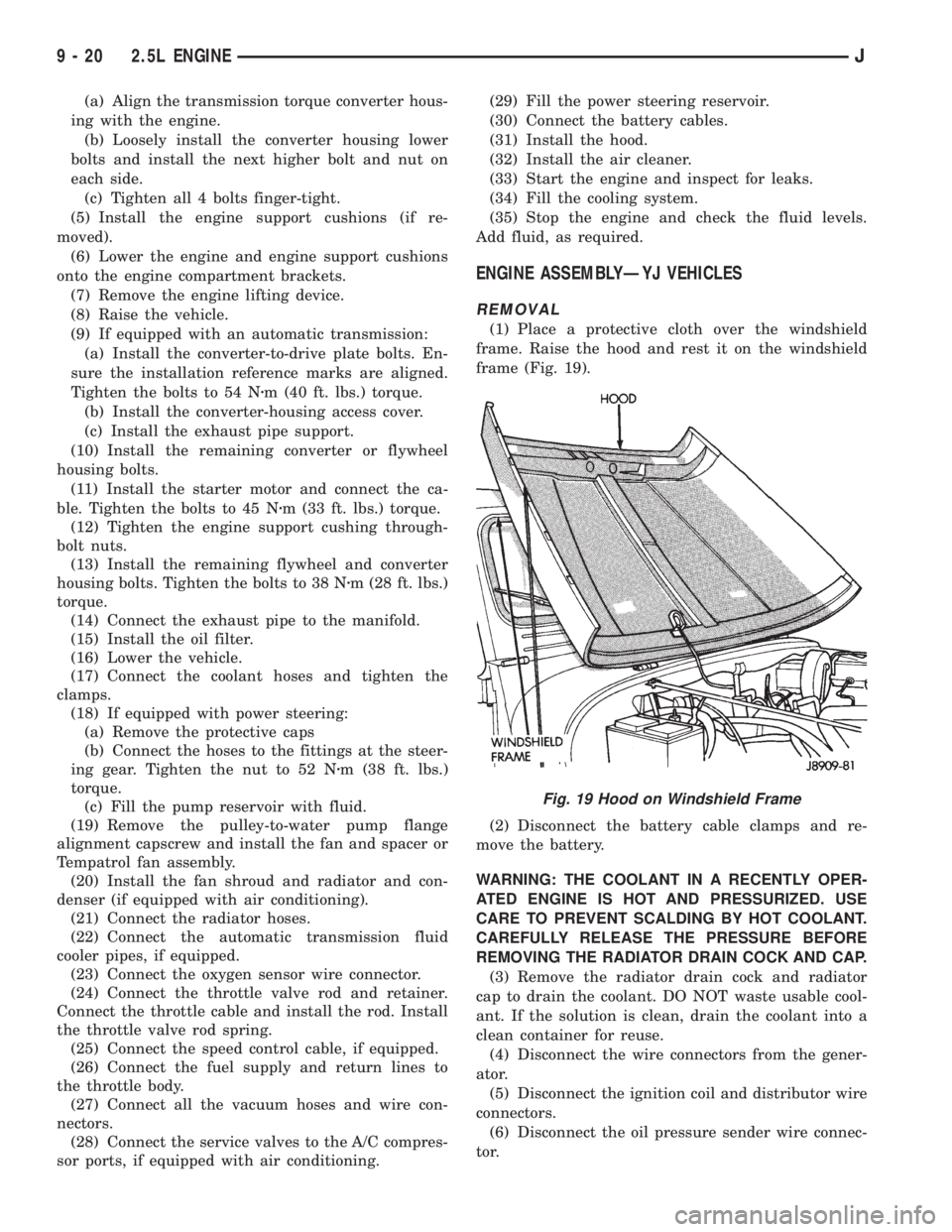
(1) Place a protective cloth over the windshield
frame. Raise the hood and rest it on the windshield
frame (Fig. 19).
(2) Disconnect the battery cable clamps and re-
move the battery.
WARNING: THE COOLANT IN A RECENTLY OPER-
ATED ENGINE IS HOT AND PRESSURIZED. USE
CARE TO PREVENT SCALDING BY HOT COOLANT.
CAREFULLY RELEASE THE PRESSURE BEFORE
REMOVING THE RADIATOR DRAIN COCK AND CAP.
(3) Remove the radiator drain cock and radiator
cap to drain the coolant. DO NOT waste usable cool-
ant. If the solution is clean, drain the coolant into a
clean container for reuse.
(4) Disconnect the wire connectors from the gener-
ator.
(5) Disconnect the ignition coil and distributor wire
connectors.
(6) Disconnect the oil pressure sender wire connec-
tor.
Fig. 19 Hood on Windshield Frame
9 - 20 2.5L ENGINEJ
Page 1300 of 2158
(7) Disconnect the wires at the starter motor sole-
noid and injection wire harness connector.
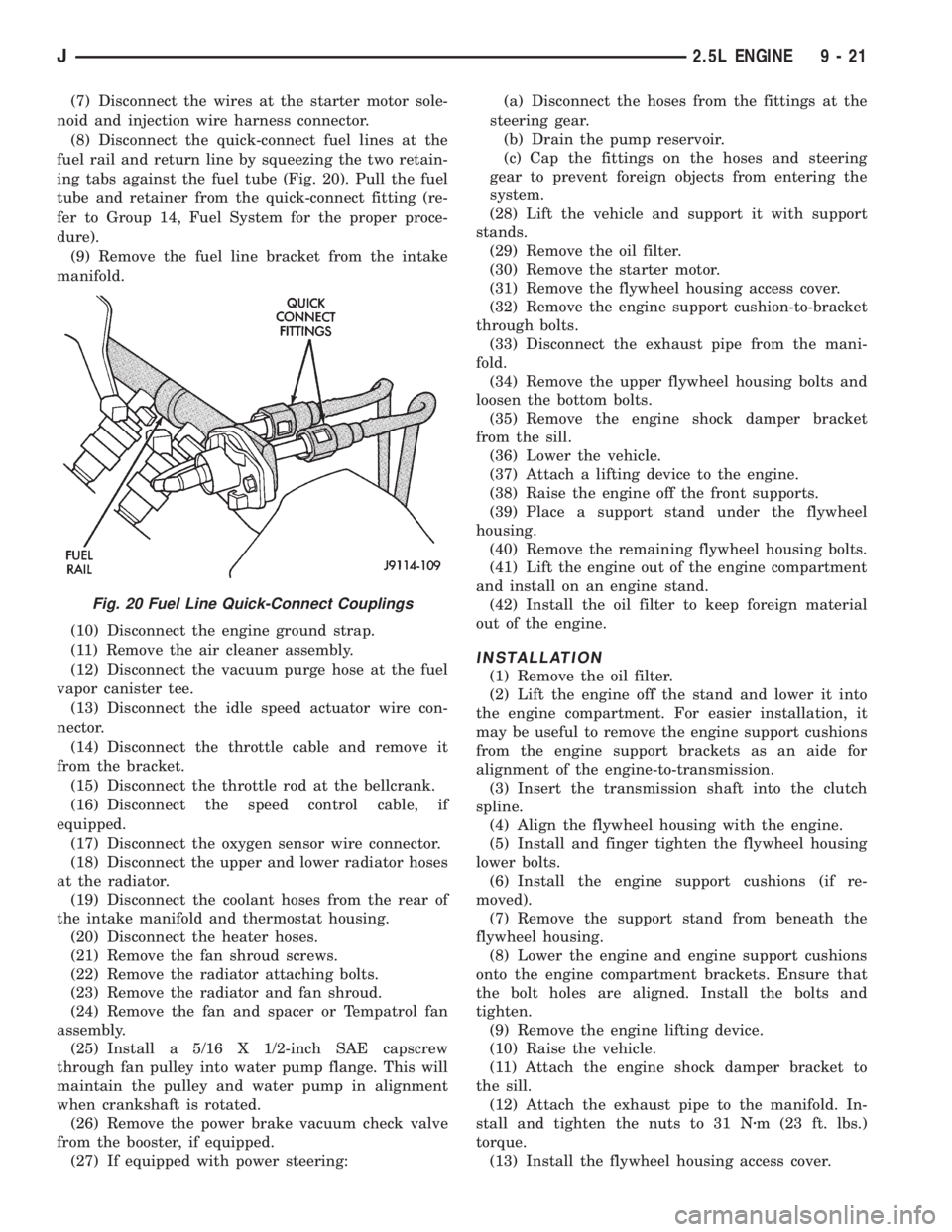
(8) Disconnect the quick-connect fuel lines at the
fuel rail and return line by squeezing the two retain-
ing tabs against the fuel tube (Fig. 20). Pull the fuel
tube and retainer from the quick-connect fitting (re-
fer to Group 14, Fuel System for the proper proce-
dure).
(9) Remove the fuel line bracket from the intake
manifold.
(10) Disconnect the engine ground strap.
(11) Remove the air cleaner assembly.
(12) Disconnect the vacuum purge hose at the fuel
vapor canister tee.
(13) Disconnect the idle speed actuator wire con-
nector.
(14) Disconnect the throttle cable and remove it
from the bracket.
(15) Disconnect the throttle rod at the bellcrank.
(16) Disconnect the speed control cable, if
equipped.
(17) Disconnect the oxygen sensor wire connector.
(18) Disconnect the upper and lower radiator hoses
at the radiator.
(19) Disconnect the coolant hoses from the rear of
the intake manifold and thermostat housing.
(20) Disconnect the heater hoses.
(21) Remove the fan shroud screws.
(22) Remove the radiator attaching bolts.
(23) Remove the radiator and fan shroud.
(24) Remove the fan and spacer or Tempatrol fan
assembly.
(25) Install a 5/16 X 1/2-inch SAE capscrew
through fan pulley into water pump flange. This will
maintain the pulley and water pump in alignment
when crankshaft is rotated.
(26) Remove the power brake vacuum check valve
from the booster, if equipped.
(27) If equipped with power steering:(a) Disconnect the hoses from the fittings at the
steering gear.
(b) Drain the pump reservoir.
(c) Cap the fittings on the hoses and steering
gear to prevent foreign objects from entering the
system.
(28) Lift the vehicle and support it with support
stands.
(29) Remove the oil filter.
(30) Remove the starter motor.
(31) Remove the flywheel housing access cover.
(32) Remove the engine support cushion-to-bracket
through bolts.
(33) Disconnect the exhaust pipe from the mani-
fold.
(34) Remove the upper flywheel housing bolts and
loosen the bottom bolts.
(35) Remove the engine shock damper bracket
from the sill.
(36) Lower the vehicle.
(37) Attach a lifting device to the engine.
(38) Raise the engine off the front supports.
(39) Place a support stand under the flywheel
housing.
(40) Remove the remaining flywheel housing bolts.
(41) Lift the engine out of the engine compartment
and install on an engine stand.
(42) Install the oil filter to keep foreign material
out of the engine.
INSTALLATION
(1) Remove the oil filter.
(2) Lift the engine off the stand and lower it into
the engine compartment. For easier installation, it
may be useful to remove the engine support cushions
from the engine support brackets as an aide for
alignment of the engine-to-transmission.
(3) Insert the transmission shaft into the clutch
spline.
(4) Align the flywheel housing with the engine.
(5) Install and finger tighten the flywheel housing
lower bolts.
(6) Install the engine support cushions (if re-
moved).
(7) Remove the support stand from beneath the
flywheel housing.
(8) Lower the engine and engine support cushions
onto the engine compartment brackets. Ensure that
the bolt holes are aligned. Install the bolts and
tighten.
(9) Remove the engine lifting device.
(10) Raise the vehicle.
(11) Attach the engine shock damper bracket to
the sill.
(12) Attach the exhaust pipe to the manifold. In-
stall and tighten the nuts to 31 Nzm (23 ft. lbs.)
torque.
(13) Install the flywheel housing access cover.
Fig. 20 Fuel Line Quick-Connect Couplings
J2.5L ENGINE 9 - 21
Page 1301 of 2158
(14) Install the remaining flywheel housing bolts.
Tighten the bolts to 38 Nzm (28 ft. lbs.) torque.
(15) Install the starter motor and connect the ca-
ble. Tighten the bolts to 45 Nzm (33 ft. lbs.) torque.
(16) Install the oil filter.
(17) Lower the vehicle.
(18) Connect the coolant hoses and tighten the
clamps.
(19) If equipped with power steering:
(a) Remove the protective caps
(b) Connect the hoses to the fittings at the steer-
ing gear. Tighten the nut to 52 Nzm (38 ft. lbs.)
torque.
(c) Fill the pump reservoir with fluid.
(20) Remove the pulley-to-water pump flange
alignment capscrew and install the fan and spacer or
Tempatrol fan assembly.
(21) Tighten the serpentine drive belt according to
the specifications listed in Group 7, Cooling System.
(22) Install the fan shroud and radiator.
(23) Connect the radiator hoses.
(24) Connect the heater hoses.
(25) Connect the throttle valve rod and retainer.
(26) Connect the throttle cable and install the rod.
(27) Install the throttle valve rod spring.
(28) Connect the speed control cable, if equipped.
(29) Connect the oxygen sensor wire connector.
(30) Install the vacuum hose and check valve on
the brake booster.
(31) Connect the coolant temperature sensor wire
connector.
(32) Connect the idle speed actuator wire connec-
tor.
(33) Connect the fuel inlet and return hoses at the
fuel rail. Verify that the quick-connect fitting assem-
bly fits securely over the fuel lines by giving the fuel
lines a firm tug.
(34) Install the fuel line bracket to the intake man-
ifold.
(35) Connect all fuel injection wire connections.
(36) Install the engine ground strap.
(37) Connect the ignition coil wire connector.
(38) Remove the coolant temperature sending unit
to permit air to escape from the block. Fill the cool-
ing system with coolant. Install the coolant tempera-
ture sending unit when the system is filled.
(39) Install the battery and connect the battery ca-
bles.
(40) Install the air cleaner bonnet to the throttle
body.
(41) Install the air cleaner.
(42) Lower the hood and secure in place.
(43) Start the engine and inspect for leaks.
(44) Stop the engine and check the fluid levels.
Add fluid, as required.ENGINE CYLINDER HEAD COVER
A cured gasket is part of the engine cylinder head
cover.
REMOVAL
(1) Disconnect negative cable from battery.
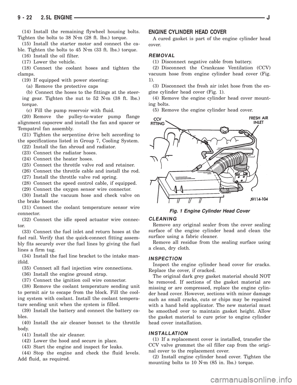
(2) Disconnect the Crankcase Ventilation (CCV)
vacuum hose from engine cylinder head cover (Fig.
1).
(3) Disconnect the fresh air inlet hose from the en-
gine cylinder head cover (Fig. 1).
(4) Remove the engine cylinder head cover mount-
ing bolts.
(5) Remove the engine cylinder head cover.
CLEANING
Remove any original sealer from the cover sealing
surface of the engine cylinder head and clean the
surface using a fabric cleaner.
Remove all residue from the sealing surface using
a clean, dry cloth.
INSPECTION
Inspect the engine cylinder head cover for cracks.
Replace the cover, if cracked.
The original dark grey gasket material should NOT
be removed. If sections of the gasket material are
missing or are compressed, replace the engine cylin-
der head cover. However, sections with minor damage
such as small cracks, cuts or chips may be repaired
with a hand held applicator. The new material must
be smoothed over to maintain gasket height. Allow
the gasket material to cure prior to engine cylinder
head cover installation.
INSTALLATION
(1) If a replacement cover is installed, transfer the
CCV valve grommet the oil filler cap from the origi-
nal cover to the replacement cover.
(2) Install engine cylinder head cover. Tighten the
mounting bolts to 10 Nzm (85 in. lbs.) torque.
Fig. 1 Engine Cylinder Head Cover
9 - 22 2.5L ENGINEJ
Page 1328 of 2158
(13) Install the drain plug. Tighten the plug to 34
Nzm (25 ft. lbs.) torque.
(14) Lower the vehicle.
(15) Install the spark plugs. Tighten the plugs to
37 Nzm (27 ft. lbs.) torque.
(16) Fill the oil pan with engine oil to the full
mark on the dipstick level.
(17) Connect negative cable to battery.
REAR MAIN OIL SEALS
REMOVAL
(1) Remove the flywheel or converter drive plate.
Discard the old bolts.
(2) Pry out the seal from around the crankshaft
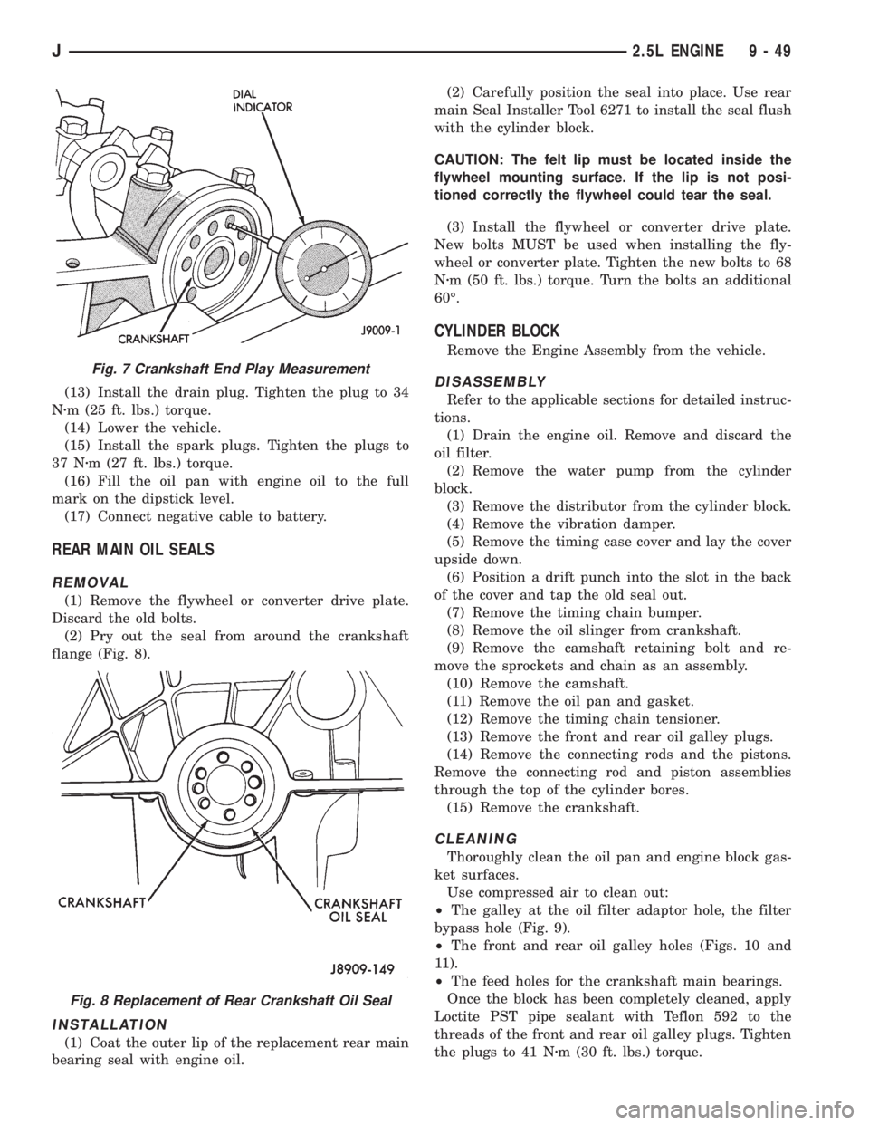
flange (Fig. 8).
INSTALLATION
(1) Coat the outer lip of the replacement rear main
bearing seal with engine oil.(2) Carefully position the seal into place. Use rear
main Seal Installer Tool 6271 to install the seal flush
with the cylinder block.
CAUTION: The felt lip must be located inside the
flywheel mounting surface. If the lip is not posi-
tioned correctly the flywheel could tear the seal.
(3) Install the flywheel or converter drive plate.
New bolts MUST be used when installing the fly-
wheel or converter plate. Tighten the new bolts to 68
Nzm (50 ft. lbs.) torque. Turn the bolts an additional
60É.
CYLINDER BLOCK
Remove the Engine Assembly from the vehicle.
DISASSEMBLY
Refer to the applicable sections for detailed instruc-
tions.
(1) Drain the engine oil. Remove and discard the
oil filter.
(2) Remove the water pump from the cylinder
block.
(3) Remove the distributor from the cylinder block.
(4) Remove the vibration damper.
(5) Remove the timing case cover and lay the cover
upside down.
(6) Position a drift punch into the slot in the back
of the cover and tap the old seal out.
(7) Remove the timing chain bumper.
(8) Remove the oil slinger from crankshaft.
(9) Remove the camshaft retaining bolt and re-
move the sprockets and chain as an assembly.
(10) Remove the camshaft.
(11) Remove the oil pan and gasket.
(12) Remove the timing chain tensioner.
(13) Remove the front and rear oil galley plugs.
(14) Remove the connecting rods and the pistons.
Remove the connecting rod and piston assemblies
through the top of the cylinder bores.
(15) Remove the crankshaft.
CLEANING
Thoroughly clean the oil pan and engine block gas-
ket surfaces.
Use compressed air to clean out:
²The galley at the oil filter adaptor hole, the filter
bypass hole (Fig. 9).
²The front and rear oil galley holes (Figs. 10 and
11).
²The feed holes for the crankshaft main bearings.
Once the block has been completely cleaned, apply
Loctite PST pipe sealant with Teflon 592 to the
threads of the front and rear oil galley plugs. Tighten
the plugs to 41 Nzm (30 ft. lbs.) torque.
Fig. 7 Crankshaft End Play Measurement
Fig. 8 Replacement of Rear Crankshaft Oil Seal
J2.5L ENGINE 9 - 49
Page 1370 of 2158
REMOVAL
(1) Remove the engine flywheel or converter drive
plate.
(2) Remove the oil pan.
(3) Remove the rear main bearing cap (No.7).
(4) Push the upper seal out of the groove. Ensure
that the crankshaft and seal groove are not damaged.
(5) Remove the lower half of the seal from the
bearing cap.
INSTALLATION
(1) Wipe the seal surface area of the crankshaft
until it is clean.
(2) Apply a thin coat of engine oil.
(3) Coat the lip of the seal with engine oil.
(4) Carefully position the upper seal into the
groove in the cylinder block. The lip of the seal faces
toward the front of the engine.
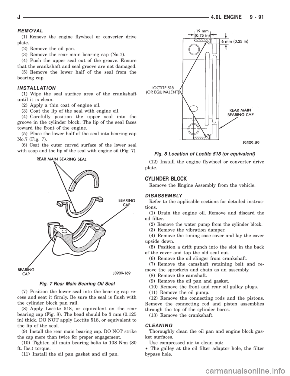
(5) Place the lower half of the seal into bearing cap
No.7 (Fig. 7).
(6) Coat the outer curved surface of the lower seal
with soap and the lip of the seal with engine oil (Fig. 7).
(7) Position the lower seal into the bearing cap re-
cess and seat it firmly. Be sure the seal is flush with
the cylinder block pan rail.
(8) Apply Loctite 518, or equivalent on the rear
bearing cap (Fig. 8). The bead should be 3 mm (0.125
in) thick. DO NOT apply Loctite 518, or equivalent to
the lip of the seal.
(9) Install the rear main bearing cap. DO NOT strike
the cap more than twice for proper engagement.
(10) Tighten all main bearing bolts to 108 Nzm (80
ft. lbs.) torque.
(11) Install the oil pan gasket and oil pan.(12) Install the engine flywheel or converter drive
plate.
CYLINDER BLOCK
Remove the Engine Assembly from the vehicle.
DISASSEMBLY
Refer to the applicable sections for detailed instruc-
tions.
(1) Drain the engine oil. Remove and discard the
oil filter.
(2) Remove the water pump from the cylinder block.
(3) Remove the vibration damper.
(4) Remove the timing case cover and lay the cover
upside down.
(5) Position a drift punch into the slot in the back
of the cover and tap the old seal out.
(6) Remove the oil slinger from crankshaft.
(7) Remove the camshaft retaining bolt and re-
move the sprockets and chain as an assembly.
(8) Remove the camshaft.
(9) Remove the oil pan and gasket.
(10) Remove the front and rear oil galley plugs.
(11) Remove the oil pump.
(12) Remove the connecting rods and the pistons.
Remove the connecting rod and piston assemblies
through the top of the cylinder bores.
(13) Remove the crankshaft.
CLEANING
Thoroughly clean the oil pan and engine block gas-
ket surfaces.
Use compressed air to clean out:
²The galley at the oil filter adaptor hole, the filter
bypass hole.
Fig. 7 Rear Main Bearing Oil Seal
Fig. 8 Location of Loctite 518 (or equivalent)
J4.0L ENGINE 9 - 91
Page 1435 of 2158
²The PCM opens the ground circuit to the A/C
clutch relay to disengage the A/C compressor clutch.
This will be done for approximately 15 seconds (if the
air conditioning system is operating).
If the vehicle has a manual transmission, the up-
shift lamp is operated by the PCM.
IGNITION SWITCH OFF MODE
When ignition switch is turned to OFF position,
the PCM stops operating the injectors, ignition coil,
ASD relay and fuel pump relay.
THROTTLE BODY
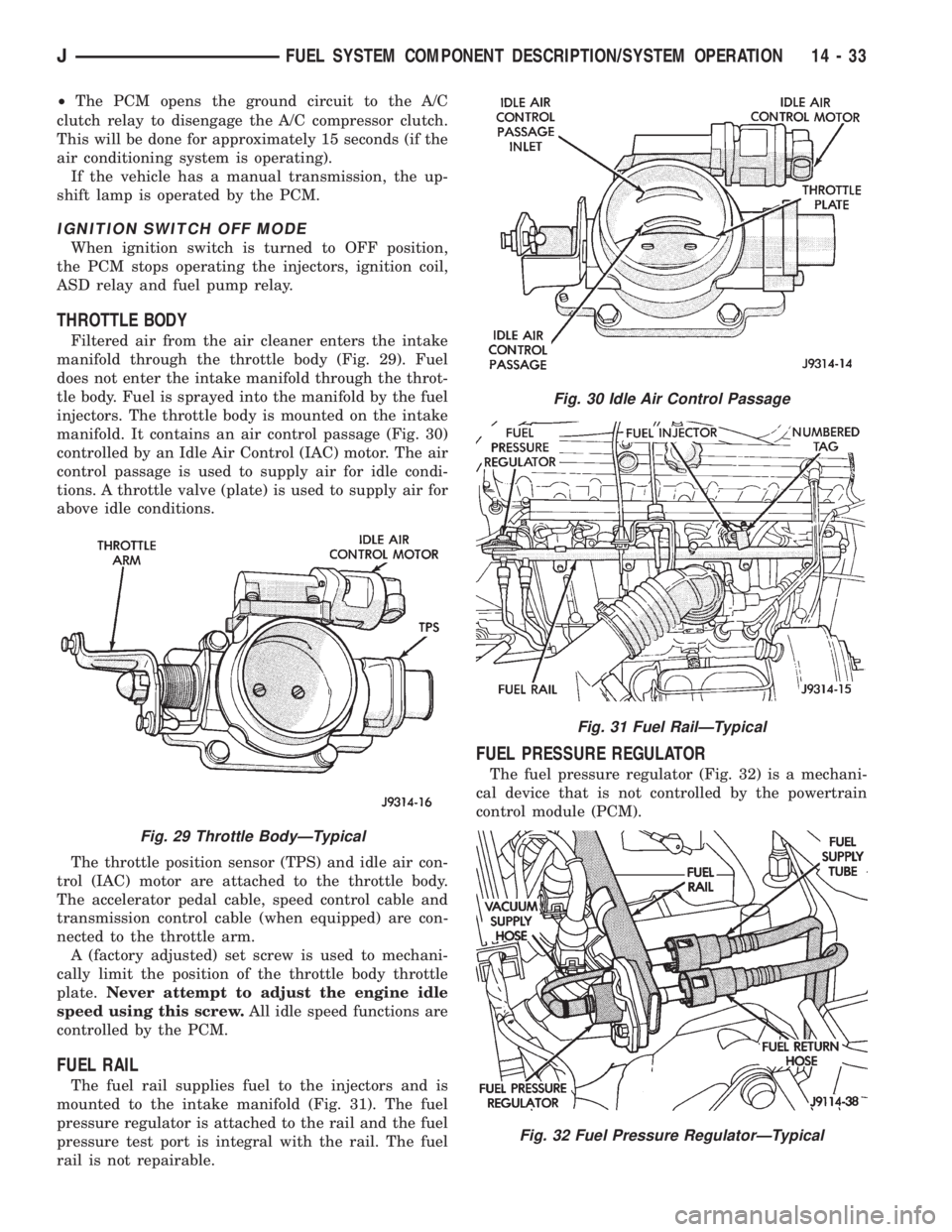
Filtered air from the air cleaner enters the intake
manifold through the throttle body (Fig. 29). Fuel
does not enter the intake manifold through the throt-
tle body. Fuel is sprayed into the manifold by the fuel
injectors. The throttle body is mounted on the intake
manifold. It contains an air control passage (Fig. 30)
controlled by an Idle Air Control (IAC) motor. The air
control passage is used to supply air for idle condi-
tions. A throttle valve (plate) is used to supply air for
above idle conditions.
The throttle position sensor (TPS) and idle air con-
trol (IAC) motor are attached to the throttle body.
The accelerator pedal cable, speed control cable and
transmission control cable (when equipped) are con-
nected to the throttle arm.
A (factory adjusted) set screw is used to mechani-
cally limit the position of the throttle body throttle
plate.Never attempt to adjust the engine idle
speed using this screw.All idle speed functions are
controlled by the PCM.
FUEL RAIL
The fuel rail supplies fuel to the injectors and is
mounted to the intake manifold (Fig. 31). The fuel
pressure regulator is attached to the rail and the fuel
pressure test port is integral with the rail. The fuel
rail is not repairable.
FUEL PRESSURE REGULATOR
The fuel pressure regulator (Fig. 32) is a mechani-
cal device that is not controlled by the powertrain
control module (PCM).
Fig. 29 Throttle BodyÐTypical
Fig. 30 Idle Air Control Passage
Fig. 31 Fuel RailÐTypical
Fig. 32 Fuel Pressure RegulatorÐTypical
JFUEL SYSTEM COMPONENT DESCRIPTION/SYSTEM OPERATION 14 - 33
Page 1453 of 2158
(8) Disconnect jumper wires from relay and 12 Volt
power source.
If continuity or resistance tests did not pass, re-
place relay. If tests passed, refer to Group 8W, Wiring
Diagrams for additional circuit information. Also re-
fer to the appropriate Powertrain Diagnostic Proce-
dures manual for operation of the DRB scan tool.
STARTER MOTOR RELAY TEST
Refer to Group 8A, Battery/Starting/Charging/Sys-
tem Diagnostics, for starter motor relay testing.
FUEL INJECTOR TEST
To perform a complete test of the fuel injectors and
their circuitry, refer to DRB scan tool and appropri-
ate Powertrain Diagnostics Procedures manual. To
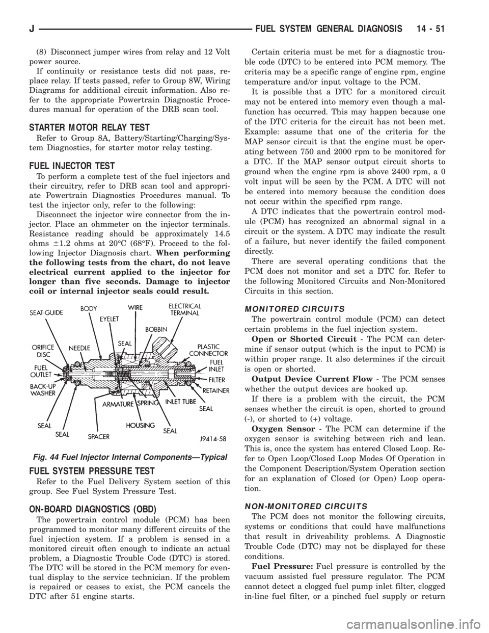
test the injector only, refer to the following:
Disconnect the injector wire connector from the in-
jector. Place an ohmmeter on the injector terminals.
Resistance reading should be approximately 14.5
ohms61.2 ohms at 20ÉC (68ÉF). Proceed to the fol-
lowing Injector Diagnosis chart.When performing
the following tests from the chart, do not leave
electrical current applied to the injector for
longer than five seconds. Damage to injector
coil or internal injector seals could result.
FUEL SYSTEM PRESSURE TEST
Refer to the Fuel Delivery System section of this
group. See Fuel System Pressure Test.
ON-BOARD DIAGNOSTICS (OBD)
The powertrain control module (PCM) has been
programmed to monitor many different circuits of the
fuel injection system. If a problem is sensed in a
monitored circuit often enough to indicate an actual
problem, a Diagnostic Trouble Code (DTC) is stored.
The DTC will be stored in the PCM memory for even-
tual display to the service technician. If the problem
is repaired or ceases to exist, the PCM cancels the
DTC after 51 engine starts.Certain criteria must be met for a diagnostic trou-
ble code (DTC) to be entered into PCM memory. The
criteria may be a specific range of engine rpm, engine
temperature and/or input voltage to the PCM.
It is possible that a DTC for a monitored circuit
may not be entered into memory even though a mal-
function has occurred. This may happen because one
of the DTC criteria for the circuit has not been met.
Example: assume that one of the criteria for the
MAP sensor circuit is that the engine must be oper-
ating between 750 and 2000 rpm to be monitored for
a DTC. If the MAP sensor output circuit shorts to
ground when the engine rpm is above 2400 rpm, a 0
volt input will be seen by the PCM. A DTC will not
be entered into memory because the condition does
not occur within the specified rpm range.
A DTC indicates that the powertrain control mod-
ule (PCM) has recognized an abnormal signal in a
circuit or the system. A DTC may indicate the result
of a failure, but never identify the failed component
directly.
There are several operating conditions that the
PCM does not monitor and set a DTC for. Refer to
the following Monitored Circuits and Non-Monitored
Circuits in this section.
MONITORED CIRCUITS
The powertrain control module (PCM) can detect
certain problems in the fuel injection system.
Open or Shorted Circuit- The PCM can deter-
mine if sensor output (which is the input to PCM) is
within proper range. It also determines if the circuit
is open or shorted.
Output Device Current Flow- The PCM senses
whether the output devices are hooked up.
If there is a problem with the circuit, the PCM
senses whether the circuit is open, shorted to ground
(-), or shorted to (+) voltage.
Oxygen Sensor- The PCM can determine if the
oxygen sensor is switching between rich and lean.
This is, once the system has entered Closed Loop. Re-
fer to Open Loop/Closed Loop Modes Of Operation in
the Component Description/System Operation section
for an explanation of Closed (or Open) Loop opera-
tion.
NON-MONITORED CIRCUITS
The PCM does not monitor the following circuits,
systems or conditions that could have malfunctions
that result in driveability problems. A Diagnostic
Trouble Code (DTC) may not be displayed for these
conditions.
Fuel Pressure:Fuel pressure is controlled by the
vacuum assisted fuel pressure regulator. The PCM
cannot detect a clogged fuel pump inlet filter, clogged
in-line fuel filter, or a pinched fuel supply or return
Fig. 44 Fuel Injector Internal ComponentsÐTypical
JFUEL SYSTEM GENERAL DIAGNOSIS 14 - 51