1995 JEEP XJ tow
[x] Cancel search: towPage 352 of 2158
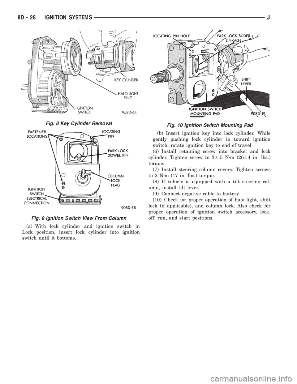
(a) With lock cylinder and ignition switch in
Lock position, insert lock cylinder into ignition
switch until it bottoms.(b) Insert ignition key into lock cylinder. While
gently pushing lock cylinder in toward ignition
switch, rotate ignition key to end of travel.
(6) Install retaining screw into bracket and lock
cylinder. Tighten screw to 36.5 Nzm (2664 in. lbs.)
torque.
(7) Install steering column covers. Tighten screws
to2Nzm (17 in. lbs.) torque.
(8) If vehicle is equipped with a tilt steering col-
umn, install tilt lever.
(9) Connect negative cable to battery.
(10) Check for proper operation of halo light, shift
lock (if applicable), and column lock. Also check for
proper operation of ignition switch accessory, lock,
off, run, and start positions.
Fig. 10 Ignition Switch Mounting PadFig. 8 Key Cylinder Removal
Fig. 9 Ignition Switch View From Column
8D - 28 IGNITION SYSTEMSJ
Page 354 of 2158
spring loaded to release when the key is released.
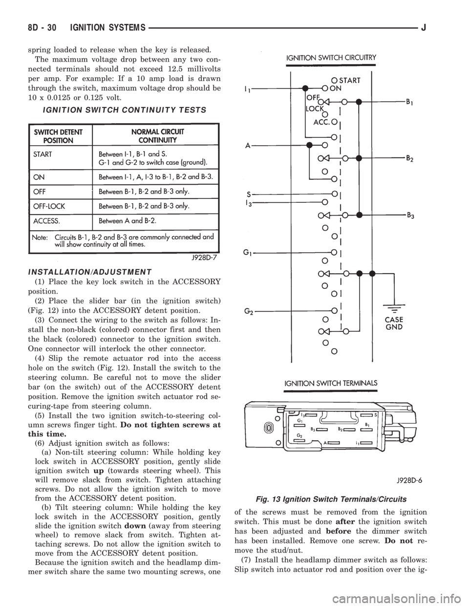
The maximum voltage drop between any two con-
nected terminals should not exceed 12.5 millivolts
per amp. For example: If a 10 amp load is drawn
through the switch, maximum voltage drop should be
10 x 0.0125 or 0.125 volt.
INSTALLATION/ADJUSTMENT
(1) Place the key lock switch in the ACCESSORY
position.
(2) Place the slider bar (in the ignition switch)
(Fig. 12) into the ACCESSORY detent position.
(3) Connect the wiring to the switch as follows: In-
stall the non-black (colored) connector first and then
the black (colored) connector to the ignition switch.
One connector will interlock the other connector.
(4) Slip the remote actuator rod into the access
hole on the switch (Fig. 12). Install the switch to the
steering column. Be careful not to move the slider
bar (on the switch) out of the ACCESSORY detent
position. Remove the ignition switch actuator rod se-
curing-tape from steering column.
(5) Install the two ignition switch-to-steering col-
umn screws finger tight.Do not tighten screws at
this time.
(6) Adjust ignition switch as follows:
(a) Non-tilt steering column: While holding key
lock switch in ACCESSORY position, gently slide
ignition switchup(towards steering wheel). This
will remove slack from switch. Tighten attaching
screws. Do not allow the ignition switch to move
from the ACCESSORY detent position.
(b) Tilt steering column: While holding the key
lock switch in the ACCESSORY position, gently
slide the ignition switchdown(away from steering
wheel) to remove slack from switch. Tighten at-
taching screws. Do not allow the ignition switch to
move from the ACCESSORY detent position.
Because the ignition switch and the headlamp dim-
mer switch share the same two mounting screws, oneof the screws must be removed from the ignition
switch. This must be doneafterthe ignition switch
has been adjusted andbeforethe dimmer switch
has been installed. Remove one screw.Do notre-
move the stud/nut.
(7) Install the headlamp dimmer switch as follows:
Slip switch into actuator rod and position over the ig-
IGNITION SWITCH CONTINUITY TESTS
Fig. 13 Ignition Switch Terminals/Circuits
8D - 30 IGNITION SYSTEMSJ
Page 355 of 2158
nition switch. Install screws finger tight. Remove the
dimmer switch actuator rod securing-tape from steer-
ing column.
(8) Adjust dimmer switch as follows: Depress the
switch slightly and insert a 3/32-inch drill bit into
the adjustment hole (Fig. 11). This is done to prevent
horizontal switch movement.
(9) Move switch toward steering wheel to remove
any lash from switch actuator rod. Tighten dimmer
and ignition switch fasteners to 4 Nzm (35 in. lbs.)
torque.(10) Install the windshield wiper intermittent con-
trol module and its bracket (if equipped).
(11) Install the negative battery cable.
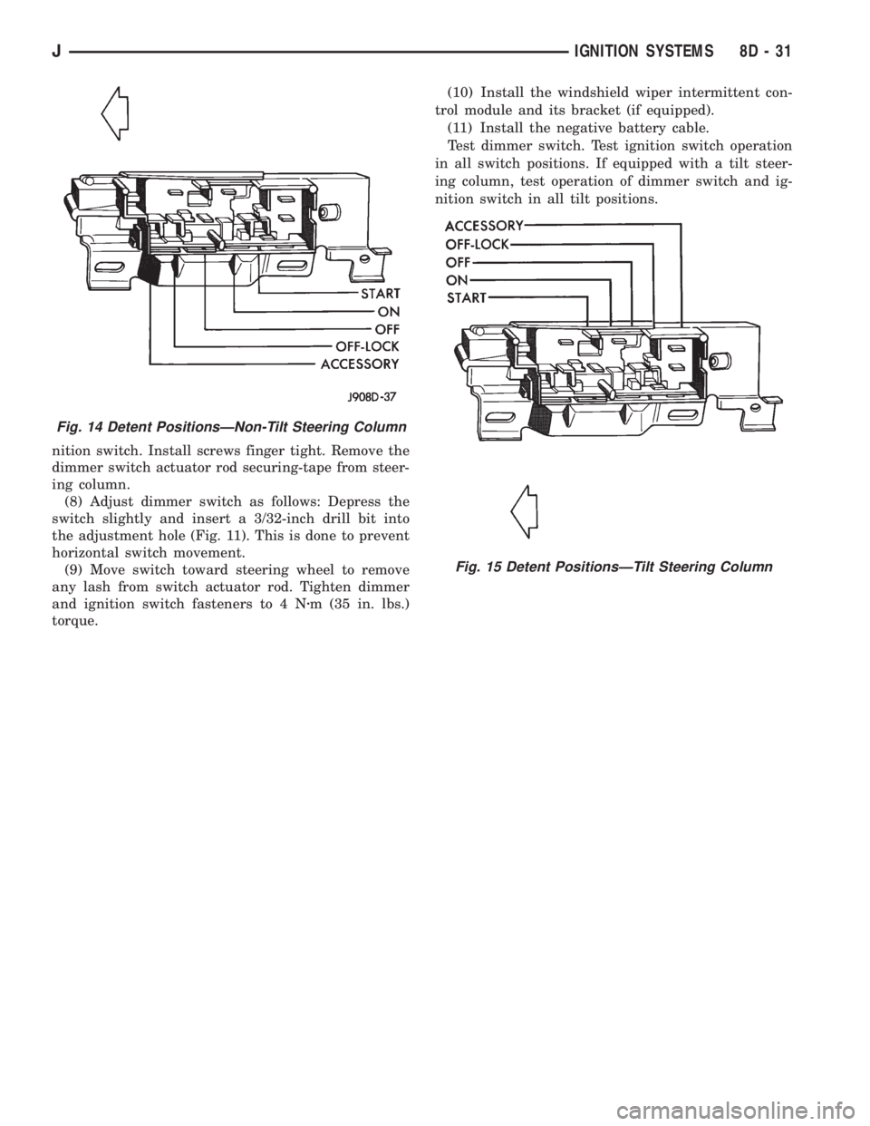
Test dimmer switch. Test ignition switch operation
in all switch positions. If equipped with a tilt steer-
ing column, test operation of dimmer switch and ig-
nition switch in all tilt positions.
Fig. 14 Detent PositionsÐNon-Tilt Steering Column
Fig. 15 Detent PositionsÐTilt Steering Column
JIGNITION SYSTEMS 8D - 31
Page 390 of 2158
TURN SIGNAL INDICATOR LAMPS
(1) Disconnect battery negative cable. Remove left
instrument cluster bezel and main cluster assembly.
Probe cavity 20 of cluster connector. Check for conti-
nuity to a good ground. There should be continuity. If
OK, go to next step. If not OK, repair open circuit to
ground.
(2) Connect battery negative cable. Install a
jumper wire from cavity 18 (left indicator) or cavity 7
(right indicator) of cluster connector to a 12-volt bat-
tery feed. Lamp should light. If OK, continue to next
step. If not OK, replace bulb.
(3) Disconnect battery negative cable. Check for
continuity between cavity 18 (left indicator) or cavity
7 (right indicator) of cluster connector and cavity H
(left front turn signal) or cavity J (right front turn
signal) of steering column wiring connector. There
should be continuity. If OK, refer to Group 8J - Turn
Signal and Hazard Warning Systems for further di-
agnosis. If not OK, repair open circuit as required.
UPSHIFT INDICATOR LAMP
(1) Disconnect battery negative cable. Unplug PCM
connector. Connect battery negative cable. Turn igni-
tion switch to ON. Install a jumper wire from cavity
54 of PCM connector (Fig. 5) to a good ground. Lamp
should light. Remove jumper from ground. Lamp
should go off. If OK, refer to Powertrain Diagnostic
Procedures manual to diagnose PCM. If not OK, turn
ignition switch to OFF and go to next step.
(2) Disconnect battery negative cable. Remove left
instrument cluster bezel and main cluster assembly.
Install a jumper wire from cavity 5 of cluster connec-
tor to a good ground. Connect battery negative cable.
Turn ignition switch to ON. Lamp should light. If
OK, go to next step. If not OK, replace bulb.
(3) Turn ignition switch to OFF. Disconnect battery
negative cable. Unplug cluster connector. Check for
continuity between cavity 5 of cluster connector and
a good ground. There should be no continuity. If OK,
go to next step. If not OK, repair short circuit as re-
quired.(4) Check for continuity between cavity 5 of cluster
connector and cavity 54 of PCM connector. There
should be continuity. If not OK, repair open circuit as
required.
CLUSTER ILLUMINATION LAMPS
(1) Check fuse 10 in fuseblock module. If OK, go to
next step. If not OK, replace fuse.
(2) Turn park lamps on at headlamp switch. Rotate
panel dimmer switch thumb-wheel to HI position,
just before interior lamps detent. Check for battery
voltage at fuse 10 in fuseblock module. Rotate panel
dimmer thumb-wheel towards LO position while ob-
serving test voltmeter. Reading should go from bat-
tery voltage to zero volts. If OK, go to next step. If
not OK, repair open circuit to headlamp switch or re-
fer to Group 8L - Lamps to diagnose headlamp
switch.
(3) Disconnect battery negative cable. Remove left
or center instrument cluster bezel and main or gauge
package cluster assembly. Unplug cluster connector.
Connect battery negative cable. Turn park lamps on
at headlamp switch. Rotate panel dimmer thumb-
wheel to HI position, just before interior lamps de-
tent. Check for battery voltage at cavity 21 of main
cluster connector, or cavity 7 of gauge package clus-
ter connector. If OK, go to next step. If not OK, re-
pair open circuit to fuse as required.
(4) Turn park lamps off. Disconnect battery nega-
tive cable. Remove fuse 10 from fuseblock module.
Probe cavity 21 of main cluster connector, or cavity 7
of gauge package cluster connector. Check for conti-
nuity to a good ground. There should be no continu-
ity. If OK, go to next step. If not OK, repair short
circuit as required.
(5) Probe cavity 20 of main cluster connector, or
cavities 1 and 13 of gauge package cluster connector.
Check for continuity to ground. There should be con-
tinuity. If not OK, repair open circuit as required.
8E - 34 INSTRUMENT PANEL AND GAUGESÐYJJ
Page 391 of 2158
SERVICE PROCEDURES
CLUSTER ASSEMBLY REMOVE/INSTALL
MAIN CLUSTER
(1) Disconnect battery negative cable.
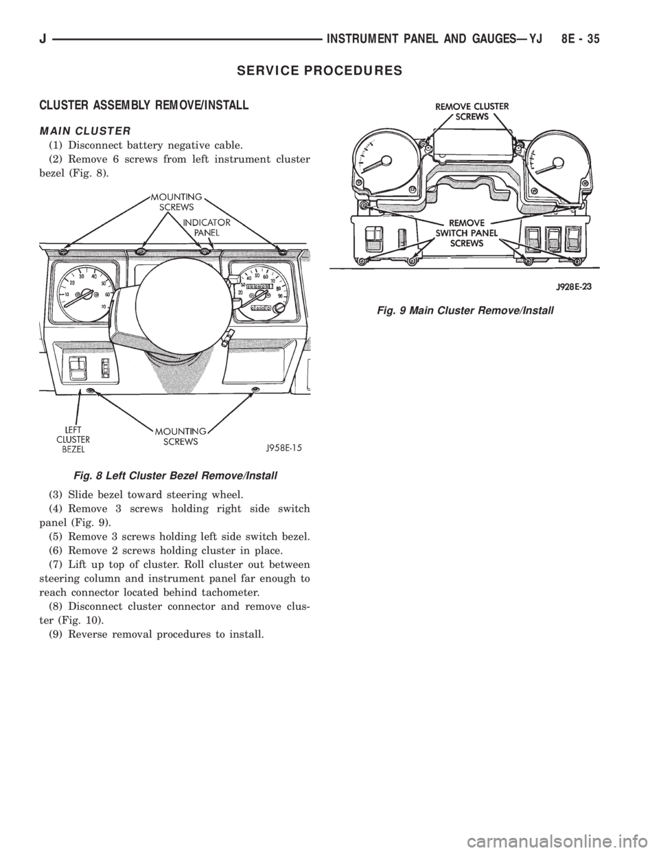
(2) Remove 6 screws from left instrument cluster
bezel (Fig. 8).
(3) Slide bezel toward steering wheel.
(4) Remove 3 screws holding right side switch
panel (Fig. 9).
(5) Remove 3 screws holding left side switch bezel.
(6) Remove 2 screws holding cluster in place.
(7) Lift up top of cluster. Roll cluster out between
steering column and instrument panel far enough to
reach connector located behind tachometer.
(8) Disconnect cluster connector and remove clus-
ter (Fig. 10).
(9) Reverse removal procedures to install.
Fig. 8 Left Cluster Bezel Remove/Install
Fig. 9 Main Cluster Remove/Install
JINSTRUMENT PANEL AND GAUGESÐYJ 8E - 35
Page 397 of 2158
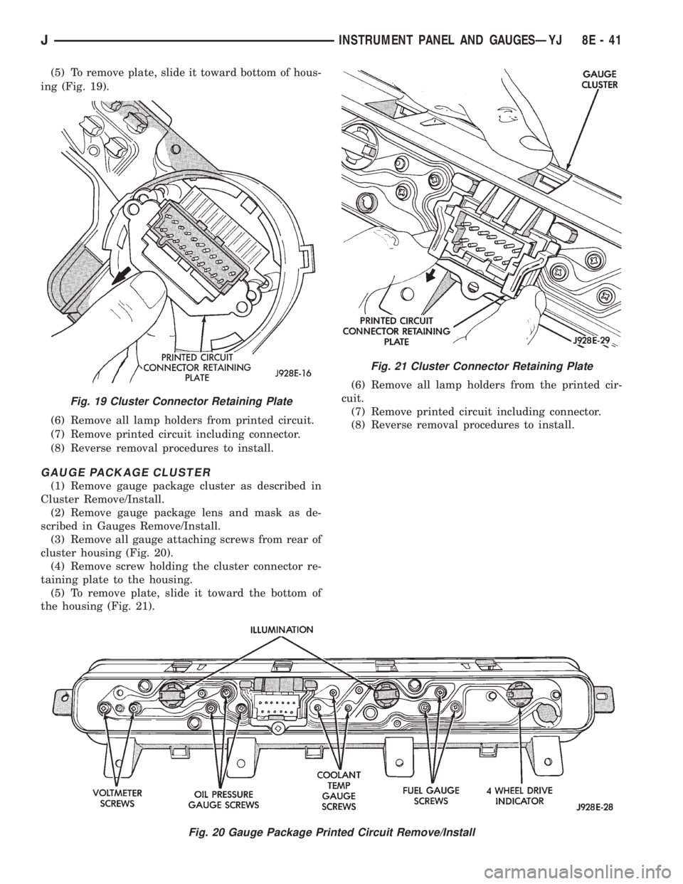
(5) To remove plate, slide it toward bottom of hous-
ing (Fig. 19).
(6) Remove all lamp holders from printed circuit.
(7) Remove printed circuit including connector.
(8) Reverse removal procedures to install.
GAUGE PACKAGE CLUSTER
(1) Remove gauge package cluster as described in
Cluster Remove/Install.
(2) Remove gauge package lens and mask as de-
scribed in Gauges Remove/Install.
(3) Remove all gauge attaching screws from rear of
cluster housing (Fig. 20).
(4) Remove screw holding the cluster connector re-
taining plate to the housing.
(5) To remove plate, slide it toward the bottom of
the housing (Fig. 21).(6) Remove all lamp holders from the printed cir-
cuit.
(7) Remove printed circuit including connector.
(8) Reverse removal procedures to install.
Fig. 20 Gauge Package Printed Circuit Remove/Install
Fig. 19 Cluster Connector Retaining Plate
Fig. 21 Cluster Connector Retaining Plate
JINSTRUMENT PANEL AND GAUGESÐYJ 8E - 41
Page 398 of 2158
HEADLAMP OR PANEL DIMMER SWITCH
REMOVE/INSTALL
(1) Disconnect battery negative cable.
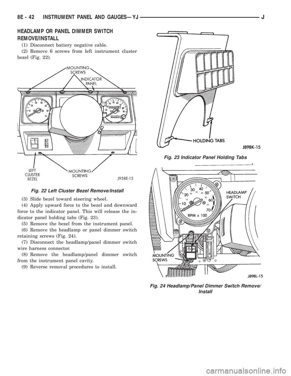
(2) Remove 6 screws from left instrument cluster
bezel (Fig. 22).
(3) Slide bezel toward steering wheel.
(4) Apply upward force to the bezel and downward
force to the indicator panel. This will release the in-
dicator panel holding tabs (Fig. 23).
(5) Remove the bezel from the instrument panel.
(6) Remove the headlamp or panel dimmer switch
retaining screws (Fig. 24).
(7) Disconnect the headlamp/panel dimmer switch
wire harness connector.
(8) Remove the headlamp/panel dimmer switch
from the instrument panel cavity.
(9) Reverse removal procedures to install.
Fig. 22 Left Cluster Bezel Remove/Install
Fig. 23 Indicator Panel Holding Tabs
Fig. 24 Headlamp/Panel Dimmer Switch Remove/
Install
8E - 42 INSTRUMENT PANEL AND GAUGESÐYJJ
Page 418 of 2158
WARNING: THE USE OF VEHICLE SPEED CON-
TROL IS NOT RECOMMENDED WHEN DRIVING
CONDITIONS DO NOT PERMIT MAINTAINING ACONSTANT SPEED, SUCH AS IN HEAVY TRAFFIC
OR ON ROADS THAT ARE WINDING, ICY, SNOW
COVERED, OR SLIPPERY.
DIAGNOSIS
Before beginning diagnosis, perform a vehicle road
test to verify reports of speed control system mal-
function. The road test should include attention to
the speedometer. Speedometer operation should be
smooth and without flutter at all speeds.
Flutter in the speedometer indicates a problem
which might cause surging in the speed control sys-
tem. The cause of any speedometer problems should
be corrected before proceeding. Refer to Group 8E -
Instrument Panel and Gauges for speedometer diag-
nosis.
If a road test verifies a system problem and the
speedometer operates properly, check for:
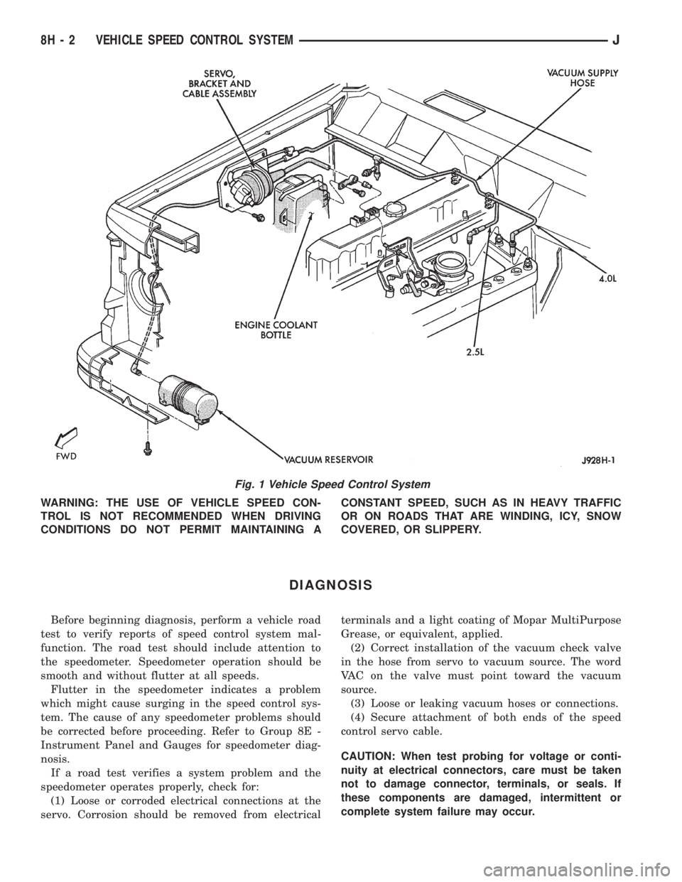
(1) Loose or corroded electrical connections at the
servo. Corrosion should be removed from electricalterminals and a light coating of Mopar MultiPurpose
Grease, or equivalent, applied.
(2) Correct installation of the vacuum check valve
in the hose from servo to vacuum source. The word
VAC on the valve must point toward the vacuum
source.
(3) Loose or leaking vacuum hoses or connections.
(4) Secure attachment of both ends of the speed
control servo cable.
CAUTION: When test probing for voltage or conti-
nuity at electrical connectors, care must be taken
not to damage connector, terminals, or seals. If
these components are damaged, intermittent or
complete system failure may occur.
Fig. 1 Vehicle Speed Control System
8H - 2 VEHICLE SPEED CONTROL SYSTEMJ