1995 JEEP XJ tow
[x] Cancel search: towPage 1281 of 2158
minutes). The use of a locating dowel is recom-
mended during assembly to prevent smearing the
material off location.
Mopar Gasket Maker should be applied sparingly
to one gasket surface. The sealant diameter should
be 1.00 mm (0.04 inch) or less. Be certain the mate-
rial surrounds each mounting hole. Excess material
can easily be wiped off. Components should be
torqued in place within 15 minutes. The use of a lo-
cating dowel is recommended during assembly to pre-
vent smearing the material off location.
ENGINE PERFORMANCE
To provide best vehicle performance and lowest ve-
hicle emissions, it is most important that the tune-up
be done accurately. Use the specifications listed on
the Vehicle Emission Control Information label found
on the engine compartment hood.
(1) Test battery specific gravity. Add water, if nec-
essary. Clean and tighten battery connections.
(2) Test cranking amperage draw (refer to Group
8B, Battery/Starter Service for the proper proce-
dures).
(3) Tighten the intake manifold bolts (refer to
Group 11, Exhaust System and Intake Manifold for
the proper specifications).
(4) Perform cylinder compression test:
(a) Check engine oil level and add oil, if neces-
sary.
(b) Drive the vehicle until engine reaches normal
operating temperature.
(c) Select a route free from traffic and other
forms of congestion, observe all traffic laws and
briskly accelerate through the gears several times.
The higher engine speed may help clean out valve
seat deposits which can prevent accurate compres-
sion readings.
CAUTION: DO NOT overspeed the engine.
(d) Remove all spark plugs from engine. As spark
plugs are being removed, check electrodes for ab-
normal firing indicatorsÐfouled, hot, oily, etc.
Record cylinder number of spark plug for future
reference.
(e) Disconnect coil wire from distributor and se-
cure to good ground to prevent a spark from start-
ing a fire.
(f) Be sure throttle blades are fully open during
the compression check.
(g) Insert compression gage adaptor into the
No.1 spark plug hole. Crank engine until maximum
pressure is reached on gauge. Record this pressure
as No.1 cylinder pressure.
(h) Repeat Step 4g for all remaining cylinders.
(i) Compression should not be less than 689 kPa
(100 psi) and not vary more than 172 kPa (25 psi)
from cylinder to cylinder.(j) If cylinder(s) have abnormally low compres-
sion pressures, repeat steps 4a through 4h.
(k) If the same cylinder(s) repeat an abnormally
low reading, it could indicate the existence of a
problem in the cylinder.
The recommended compression pressures are
to be used only as a guide to diagnosing engine
problems. An engine should NOT be disassem-
bled to determine the cause of low compression
unless some malfunction is present.
(5) Clean or replace spark plugs as necessary. Ad-
just gap (refer to Group 8D, Ignition System for gap
adjustment and torque).
(6) Test resistance of spark plug cables (refer to
Group 8D, Ignition System).
(7) Inspect the primary wire. Test coil output volt-
age, primary and secondary resistance. Replace parts
as necessary (refer to Group 8D, Ignition System and
make necessary adjustment).
(8) Perform a combustion analysis.
(9) Test fuel pump for pressure (refer to Group 14,
Fuel System for the proper specifications).
(10) Inspect air filter element (refer to Group 0,
Lubrication and Maintenance for the proper proce-
dure).
(11) Inspect crankcase ventilation system (refer to
Group 0, Lubrication and Maintenance for the proper
procedure).
(12) For emission controls refer to Group 25, Emis-
sion Controls System for service procedures.
(13) Inspect and adjust accessory belt drives (refer
to Group 7, Cooling System for the proper adjust-
ments).
(14) Road test vehicle as a final test.
HONING CYLINDER BORES
Before honing, stuff plenty of clean shop towels un-
der the bores and over the crankshaft to keep abra-
sive materials from entering the crankshaft area.
(1) Used carefully, the Cylinder Bore Sizing Hone
C-823 equipped with 220 grit stones, is the best tool
for this job. In addition to deglazing, it will reduce
taper and out-of-round as well as removing light
scuffing, scoring or scratches. Usually a few strokes
will clean up a bore and maintain the required lim-
its.
CAUTION: DO NOT use rigid type hones to remove
cylinder wall glaze.
(2) Deglazing of the cylinder walls may be done if
the cylinder bore is straight and round. Use a cylin-
der surfacing hone, Honing Tool C-3501, equipped
with 280 grit stones (C-3501-3810). 20-60 strokes, de-
pending on the bore condition, will be sufficient to
provide a satisfactory surface. Using honing oil
C-3501-3880 or a light honing oil available from ma-
jor oil distributors.
9 - 2 ENGINESJ
Page 1283 of 2158
CONNECTING ROD BEARING CLEARANCE
Engine connecting rod bearing clearances can be
determined by use of Plastigage, or equivalent. The
following is the recommended procedures for the use
of Plastigage:
(1) Remove oil film from surface to be checked.
Plastigage is soluble in oil.
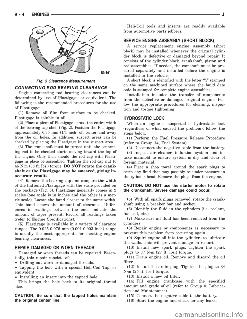
(2) Place a piece of Plastigage across the entire width
of the bearing cap shell (Fig. 2). Position the Plastigage
approximately 6.35 mm (1/4 inch) off center and away
from the oil holes. In addition, suspect areas can be
checked by placing the Plastigage in the suspect area.
(3) The crankshaft must be turned until the connect-
ing rod to be checked starts moving toward the top of
the engine. Only then should the rod cap with Plasti-
gage in place be assembled. Tighten the rod cap nut to
45 Nzm (33 ft. lbs.) torque.DO NOT rotate the crank-
shaft or the Plastigage may be smeared, giving in-
accurate results.
(4) Remove the bearing cap and compare the width
of the flattened Plastigage with the scale provided on
the package (Fig. 3). Plastigage generally comes in 2
scales (one scale is in inches and the other is a met-
ric scale). Locate the band closest to the same width.
This band shows the amount of clearance. Differ-
ences in readings between the ends indicate the
amount of taper present. Record all readings taken
(refer to Engine Specifications).
(5) Plastigage is available in a variety of clearance
ranges. The 0.025-0.076 mm (0.001-0.003 inch) range
is usually the most appropriate for checking engine
bearing clearances.
REPAIR DAMAGED OR WORN THREADS
Damaged or worn threads can be repaired. Essen-
tially, this repair consists of:
²Drilling out worn or damaged threads.
²Tapping the hole with a special Heli-Coil Tap, or
equivalent.
²Installing an insert into the tapped hole.
This brings the hole back to its original thread
size.
CAUTION: Be sure that the tapped holes maintain
the original center line.Heli-Coil tools and inserts are readily available
from automotive parts jobbers.
SERVICE ENGINE ASSEMBLY (SHORT BLOCK)
A service replacement engine assembly (short
block) may be installed whenever the original cylin-
der block is defective or damaged beyond repair. It
consists of the cylinder block, crankshaft, piston and
rod assemblies. If needed, the camshaft must be pro-
cured separately and installed before the engine is
installed in the vehicle.
A short block is identified with the letter ``S'' stamped
on the same machined surface where the build date
code is stamped for complete engine assemblies.
Installation includes the transfer of components
from the defective or damaged original engine. Fol-
low the appropriate procedures for cleaning, inspec-
tion and torque tightening.
HYDROSTATIC LOCK
When an engine is suspected of hydrostatic lock
(regardless of what caused the problem), follow the
steps below.
(1) Perform the Fuel Pressure Release Procedure
(refer to Group 14, Fuel System).
(2) Disconnect the negative cable from the battery.
(3) Inspect air cleaner, induction system and in-
take manifold to ensure system is dry and clear of
foreign material.
(4) Place a shop towel around the spark plugs to
catch any fluid that may possibly be under pressure in
the cylinder head. Remove the plugs from the engine.
CAUTION: DO NOT use the starter motor to rotate
the crankshaft. Severe damage could occur.
(5) With all spark plugs removed, rotate the crank-
shaft using a breaker bar and socket.
(6) Identify the fluid in the cylinders (i.e. coolant,
fuel, oil, etc.).
(7) Make sure all fluid has been removed from the
cylinders.
(8) Repair engine or components as necessary to
prevent this problem from occurring again.
(9) Squirt engine oil into the cylinders to lubricate
the walls. This will prevent damage on restart.
(10) Install new spark plugs. Tighten the spark
plugs to 37 Nzm (27 ft. lbs.) torque.
(11) Drain engine oil. Remove and discard the oil
filter.
(12) Install the drain plug. Tighten the plug to 34
Nzm (25 ft. lbs.) torque.
(13) Install a new oil filter.
(14) Fill engine crankcase with the specified
amount and grade of oil (refer to Group 0, Lubrica-
tion and Maintenance).
(15) Connect the negative cable to the battery.
(16) Start the engine and check for any leaks.
Fig. 3 Clearance Measurement
9 - 4 ENGINESJ
Page 1305 of 2158
(9) If equipped, disconnect the power steering
pump bracket. Set the pump and bracket aside. DO
NOT disconnect the hoses.
(10) Remove the fuel lines and vacuum advance
hose.
(11) Remove the intake and engine exhaust mani-
folds from the engine cylinder head (refer to Group
11, Exhaust System and Intake Manifold for the
proper procedures).
(12) Disconnect the ignition wires and remove the
spark plugs.
(13) Disconnect the temperature sending unit wire
connector.
(14) Remove the ignition coil and bracket assem-
bly.
(15) Remove the engine cylinder head bolts.
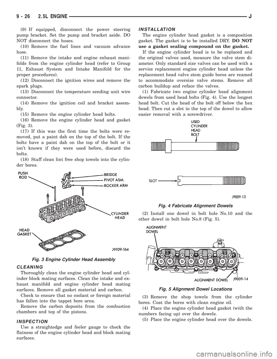
(16) Remove the engine cylinder head and gasket
(Fig. 3).
(17) If this was the first time the bolts were re-
moved, put a paint dab on the top of the bolt. If the
bolts have a paint dab on the top of the bolt or it
isn't known if they were used before, discard the
bolts.
(18) Stuff clean lint free shop towels into the cylin-
der bores.
CLEANING
Thoroughly clean the engine cylinder head and cyl-
inder block mating surfaces. Clean the intake and ex-
haust manifold and engine cylinder head mating
surfaces. Remove all gasket material and carbon.
Check to ensure that no coolant or foreign material
has fallen into the tappet bore area.
Remove the carbon deposits from the combustion
chambers and top of the pistons.
INSPECTION
Use a straightedge and feeler gauge to check the
flatness of the engine cylinder head and block mating
surfaces.
INSTALLATION
The engine cylinder head gasket is a composition
gasket. The gasket is to be installed DRY.DO NOT
use a gasket sealing compound on the gasket.
If the engine cylinder head is to be replaced and
the original valves used, measure the valve stem di-
ameter. Only standard size valves can be used with a
service replacement engine cylinder head unless the
replacement head valve stem guide bores are reamed
to accommodate oversize valve stems. Remove all
carbon buildup and reface the valves.
(1) Fabricate two engine cylinder head alignment
dowels from used head bolts (Fig. 4). Use the longest
head bolt. Cut the head of the bolt off below the hex
head. Then cut a slot in the top of the dowel to allow
easier removal with a screwdriver.
(2) Install one dowel in bolt hole No.10 and the
other dowel in bolt hole No.8 (Fig. 5).
(3) Remove the shop towels from the cylinder
bores. Coat the bores with clean engine oil.
(4) Place the engine cylinder head gasket (with the
numbers facing up) over the dowels.
(5) Place the engine cylinder head over the dowels.
Fig. 3 Engine Cylinder Head Assembly
Fig. 4 Fabricate Alignment Dowels
Fig. 5 Alignment Dowel Locations
9 - 26 2.5L ENGINEJ
Page 1310 of 2158
oil on the vibration damper hub contact surface of
the seal.
(9) Apply Mopar Silicone Rubber Adhesive Sealant
to the keyway in the crankshaft and insert the key.
With the key inserted in the keyway in the crank-
shaft, install the vibration damper, washer and bolt.
Lubricate and tighten the bolt to 108 Nzm (80 ft. lbs.)
torque.
(10) Install the serpentine belt and tighten to the
specified tension (refer to Group 7, Cooling Systems
for the proper specifications and procedures).
(11) Install the radiator shroud.
(12) Connect negative cable to battery.
TIMING CASE COVER
REMOVAL
(1) Disconnect negative cable from battery.
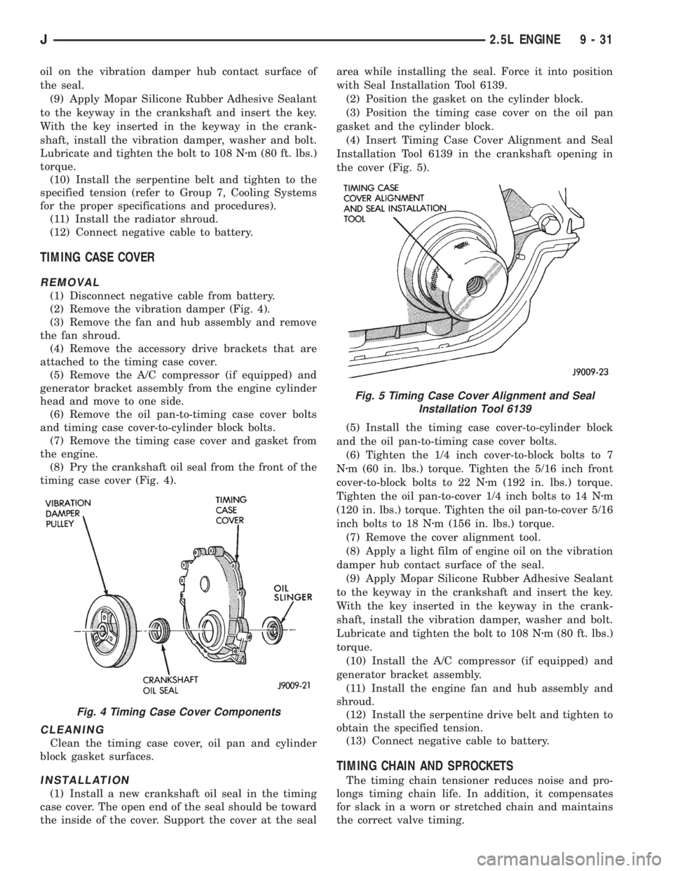
(2) Remove the vibration damper (Fig. 4).
(3) Remove the fan and hub assembly and remove
the fan shroud.
(4) Remove the accessory drive brackets that are
attached to the timing case cover.
(5) Remove the A/C compressor (if equipped) and
generator bracket assembly from the engine cylinder
head and move to one side.
(6) Remove the oil pan-to-timing case cover bolts
and timing case cover-to-cylinder block bolts.
(7) Remove the timing case cover and gasket from
the engine.
(8) Pry the crankshaft oil seal from the front of the
timing case cover (Fig. 4).
CLEANING
Clean the timing case cover, oil pan and cylinder
block gasket surfaces.
INSTALLATION
(1) Install a new crankshaft oil seal in the timing
case cover. The open end of the seal should be toward
the inside of the cover. Support the cover at the sealarea while installing the seal. Force it into position
with Seal Installation Tool 6139.
(2) Position the gasket on the cylinder block.
(3) Position the timing case cover on the oil pan
gasket and the cylinder block.
(4) Insert Timing Case Cover Alignment and Seal
Installation Tool 6139 in the crankshaft opening in
the cover (Fig. 5).
(5) Install the timing case cover-to-cylinder block
and the oil pan-to-timing case cover bolts.
(6) Tighten the 1/4 inch cover-to-block bolts to 7
Nzm (60 in. lbs.) torque. Tighten the 5/16 inch front
cover-to-block bolts to 22 Nzm (192 in. lbs.) torque.
Tighten the oil pan-to-cover 1/4 inch bolts to 14 Nzm
(120 in. lbs.) torque. Tighten the oil pan-to-cover 5/16
inch bolts to 18 Nzm (156 in. lbs.) torque.
(7) Remove the cover alignment tool.
(8) Apply a light film of engine oil on the vibration
damper hub contact surface of the seal.
(9) Apply Mopar Silicone Rubber Adhesive Sealant
to the keyway in the crankshaft and insert the key.
With the key inserted in the keyway in the crank-
shaft, install the vibration damper, washer and bolt.
Lubricate and tighten the bolt to 108 Nzm (80 ft. lbs.)
torque.
(10) Install the A/C compressor (if equipped) and
generator bracket assembly.
(11) Install the engine fan and hub assembly and
shroud.
(12) Install the serpentine drive belt and tighten to
obtain the specified tension.
(13) Connect negative cable to battery.
TIMING CHAIN AND SPROCKETS
The timing chain tensioner reduces noise and pro-
longs timing chain life. In addition, it compensates
for slack in a worn or stretched chain and maintains
the correct valve timing.
Fig. 4 Timing Case Cover Components
Fig. 5 Timing Case Cover Alignment and Seal
Installation Tool 6139
J2.5L ENGINE 9 - 31
Page 1311 of 2158
REMOVAL
(1) Disconnect negative cable from battery.
(2) Remove the fan and shroud.
(3) Remove the serpentine drive belt.
(4) Remove the crankshaft vibration damper.
(5) Remove the timing case cover.
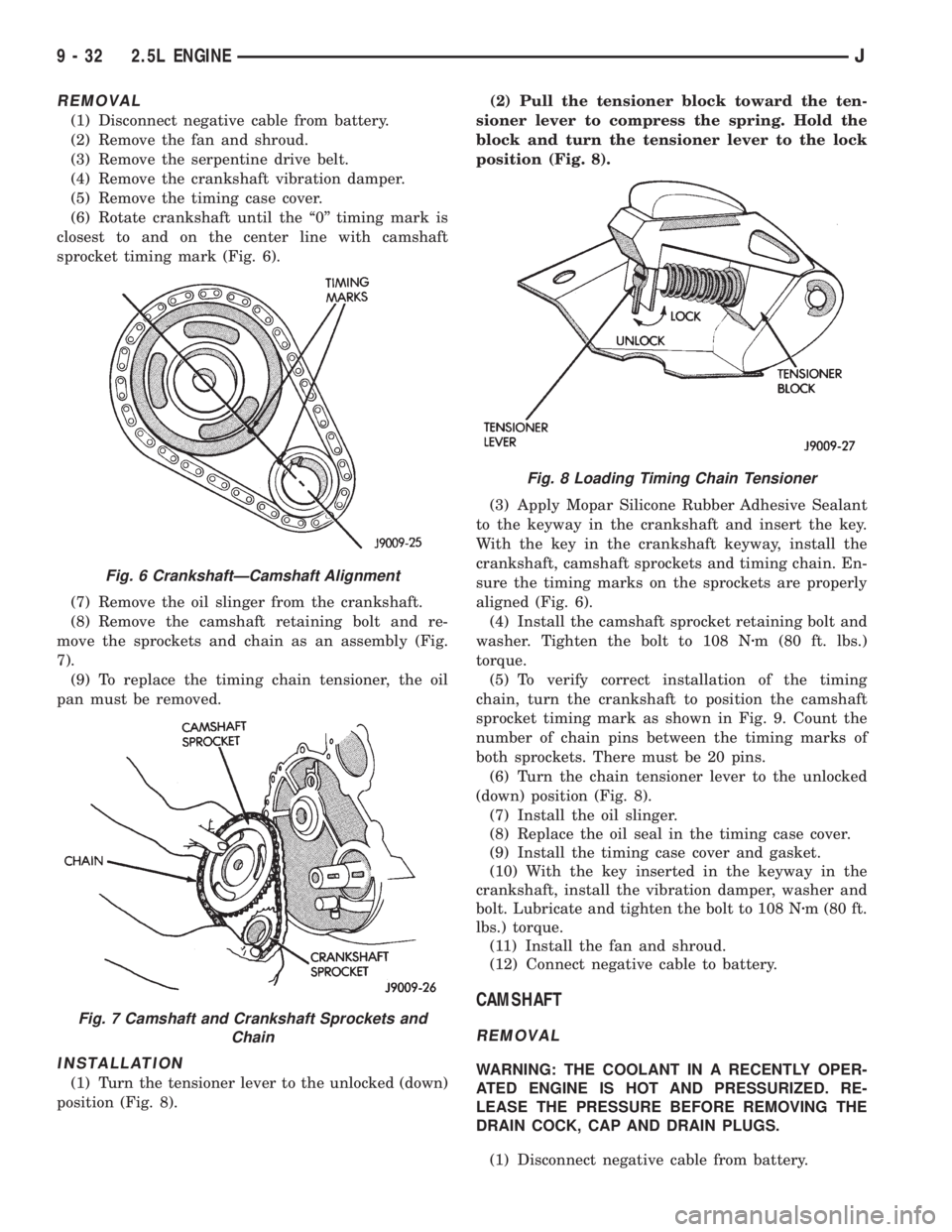
(6) Rotate crankshaft until the ``0'' timing mark is
closest to and on the center line with camshaft
sprocket timing mark (Fig. 6).
(7) Remove the oil slinger from the crankshaft.
(8) Remove the camshaft retaining bolt and re-
move the sprockets and chain as an assembly (Fig.
7).
(9) To replace the timing chain tensioner, the oil
pan must be removed.
INSTALLATION
(1) Turn the tensioner lever to the unlocked (down)
position (Fig. 8).(2) Pull the tensioner block toward the ten-
sioner lever to compress the spring. Hold the
block and turn the tensioner lever to the lock
position (Fig. 8).
(3) Apply Mopar Silicone Rubber Adhesive Sealant
to the keyway in the crankshaft and insert the key.
With the key in the crankshaft keyway, install the
crankshaft, camshaft sprockets and timing chain. En-
sure the timing marks on the sprockets are properly
aligned (Fig. 6).
(4) Install the camshaft sprocket retaining bolt and
washer. Tighten the bolt to 108 Nzm (80 ft. lbs.)
torque.
(5) To verify correct installation of the timing
chain, turn the crankshaft to position the camshaft
sprocket timing mark as shown in Fig. 9. Count the
number of chain pins between the timing marks of
both sprockets. There must be 20 pins.
(6) Turn the chain tensioner lever to the unlocked
(down) position (Fig. 8).
(7) Install the oil slinger.
(8) Replace the oil seal in the timing case cover.
(9) Install the timing case cover and gasket.
(10) With the key inserted in the keyway in the
crankshaft, install the vibration damper, washer and
bolt. Lubricate and tighten the bolt to 108 Nzm (80 ft.
lbs.) torque.
(11) Install the fan and shroud.
(12) Connect negative cable to battery.
CAMSHAFT
REMOVAL
WARNING: THE COOLANT IN A RECENTLY OPER-
ATED ENGINE IS HOT AND PRESSURIZED. RE-
LEASE THE PRESSURE BEFORE REMOVING THE
DRAIN COCK, CAP AND DRAIN PLUGS.
(1) Disconnect negative cable from battery.
Fig. 6 CrankshaftÐCamshaft Alignment
Fig. 7 Camshaft and Crankshaft Sprockets and
Chain
Fig. 8 Loading Timing Chain Tensioner
9 - 32 2.5L ENGINEJ
Page 1312 of 2158
(2) Drain the cooling system. DO NOT waste reus-
able coolant. If the solution is clean, drain it into a
clean container for reuse.
(3) Remove the radiator or radiator and condenser,
if equipped with A/C (refer to Group 7, Cooling Sys-
tem for the proper procedure).
(4) Scribe a mark on the distributor housing in line
with the lip of the rotor.
(5) Scribe a mark on the distributor housing near
the clamp and continue the scribe mark on the cylin-
der block in line with the distributor mark.
(6) For ease of installation, note the position of the
rotor and distributor housing in relation to adjacent
engine components.
(7) Remove the distributor and ignition wires.
(8) Remove the engine cylinder head cover.
(9) Remove the rocker arms, bridges and pivots.
(10) Remove the push rods.
(11) Remove the hydraulic valve tappets from the
engine cylinder head.
(12) Remove the vibration damper.
(13) Remove the timing case cover.
(14) Remove the timing chain and sprockets.
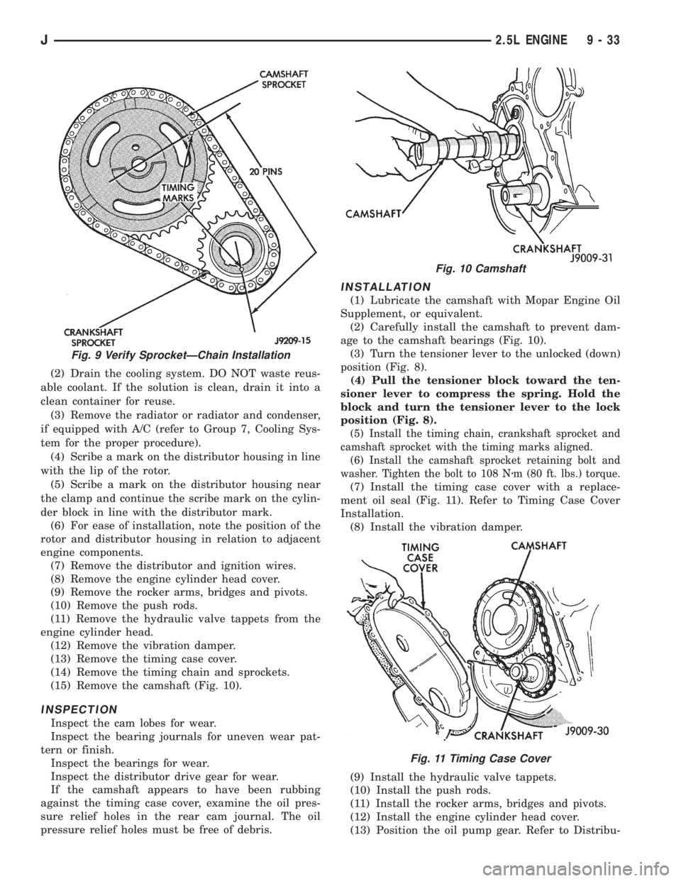
(15) Remove the camshaft (Fig. 10).
INSPECTION
Inspect the cam lobes for wear.
Inspect the bearing journals for uneven wear pat-
tern or finish.
Inspect the bearings for wear.
Inspect the distributor drive gear for wear.
If the camshaft appears to have been rubbing
against the timing case cover, examine the oil pres-
sure relief holes in the rear cam journal. The oil
pressure relief holes must be free of debris.
INSTALLATION
(1) Lubricate the camshaft with Mopar Engine Oil
Supplement, or equivalent.
(2) Carefully install the camshaft to prevent dam-
age to the camshaft bearings (Fig. 10).
(3) Turn the tensioner lever to the unlocked (down)
position (Fig. 8).
(4) Pull the tensioner block toward the ten-
sioner lever to compress the spring. Hold the
block and turn the tensioner lever to the lock
position (Fig. 8).
(5) Install the timing chain, crankshaft sprocket and
camshaft sprocket with the timing marks aligned.
(6) Install the camshaft sprocket retaining bolt and
washer. Tighten the bolt to 108 Nzm (80 ft. lbs.) torque.
(7) Install the timing case cover with a replace-
ment oil seal (Fig. 11). Refer to Timing Case Cover
Installation.
(8) Install the vibration damper.
(9) Install the hydraulic valve tappets.
(10) Install the push rods.
(11) Install the rocker arms, bridges and pivots.
(12) Install the engine cylinder head cover.
(13) Position the oil pump gear. Refer to Distribu-
Fig. 9 Verify SprocketÐChain Installation
Fig. 10 Camshaft
Fig. 11 Timing Case Cover
J2.5L ENGINE 9 - 33
Page 1323 of 2158
(9) The top compression ring (the scraping edge is
gray in color) has a chamfer on the TOP of the inside
edge (Fig. 16). This ring may also have 1 dot located
on the top surface.
(10) Using a ring installer, install the top ring with
the chamfer facing up (Fig. 17). The dot will be fac-
ing up.
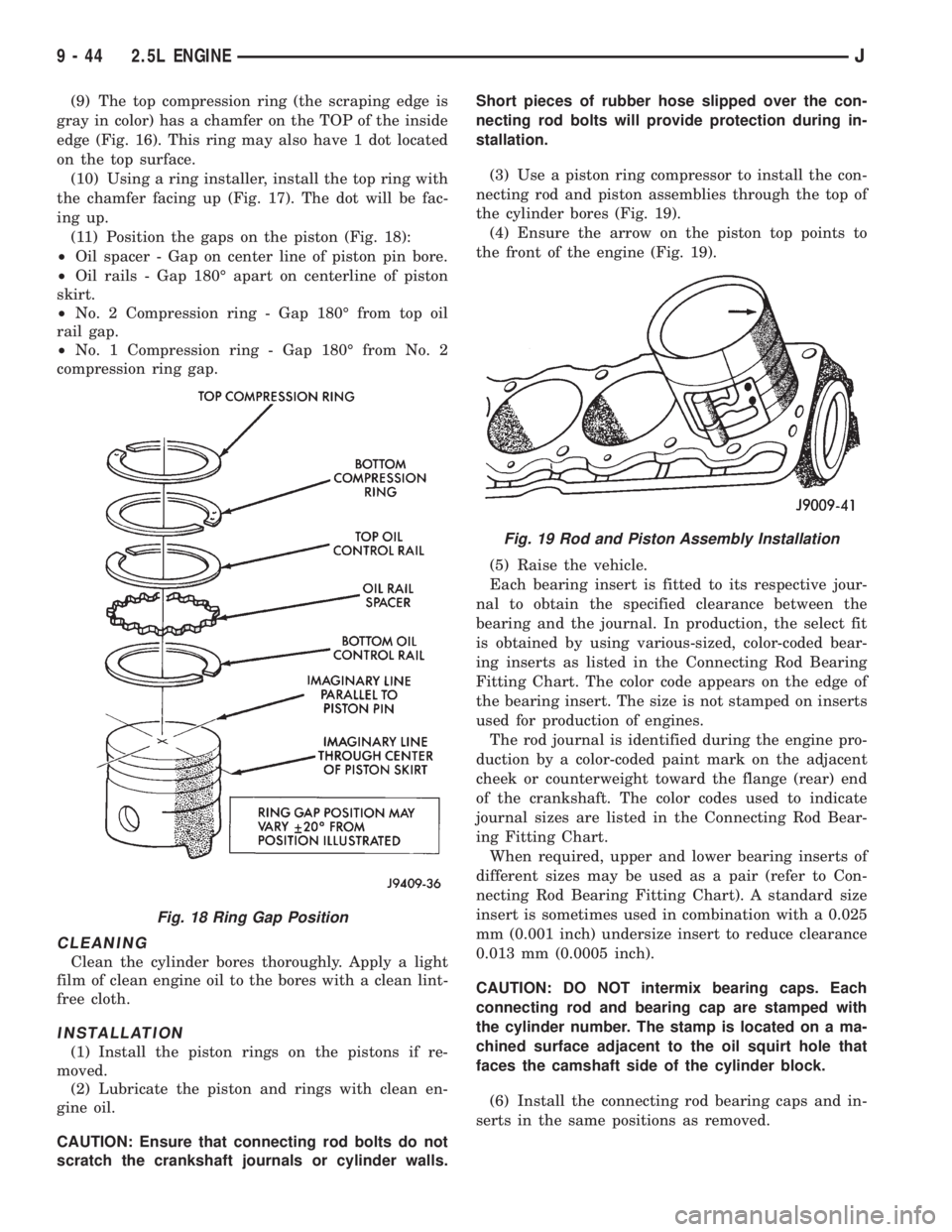
(11) Position the gaps on the piston (Fig. 18):
²Oil spacer - Gap on center line of piston pin bore.
²Oil rails - Gap 180É apart on centerline of piston
skirt.
²No. 2 Compression ring - Gap 180É from top oil
rail gap.
²No. 1 Compression ring - Gap 180É from No. 2
compression ring gap.
CLEANING
Clean the cylinder bores thoroughly. Apply a light
film of clean engine oil to the bores with a clean lint-
free cloth.
INSTALLATION
(1) Install the piston rings on the pistons if re-
moved.
(2) Lubricate the piston and rings with clean en-
gine oil.
CAUTION: Ensure that connecting rod bolts do not
scratch the crankshaft journals or cylinder walls.Short pieces of rubber hose slipped over the con-
necting rod bolts will provide protection during in-
stallation.
(3) Use a piston ring compressor to install the con-
necting rod and piston assemblies through the top of
the cylinder bores (Fig. 19).
(4) Ensure the arrow on the piston top points to
the front of the engine (Fig. 19).
(5) Raise the vehicle.
Each bearing insert is fitted to its respective jour-
nal to obtain the specified clearance between the
bearing and the journal. In production, the select fit
is obtained by using various-sized, color-coded bear-
ing inserts as listed in the Connecting Rod Bearing
Fitting Chart. The color code appears on the edge of
the bearing insert. The size is not stamped on inserts
used for production of engines.
The rod journal is identified during the engine pro-
duction by a color-coded paint mark on the adjacent
cheek or counterweight toward the flange (rear) end
of the crankshaft. The color codes used to indicate
journal sizes are listed in the Connecting Rod Bear-
ing Fitting Chart.
When required, upper and lower bearing inserts of
different sizes may be used as a pair (refer to Con-
necting Rod Bearing Fitting Chart). A standard size
insert is sometimes used in combination with a 0.025
mm (0.001 inch) undersize insert to reduce clearance
0.013 mm (0.0005 inch).
CAUTION: DO NOT intermix bearing caps. Each
connecting rod and bearing cap are stamped with
the cylinder number. The stamp is located on a ma-
chined surface adjacent to the oil squirt hole that
faces the camshaft side of the cylinder block.
(6) Install the connecting rod bearing caps and in-
serts in the same positions as removed.
Fig. 18 Ring Gap Position
Fig. 19 Rod and Piston Assembly Installation
9 - 44 2.5L ENGINEJ
Page 1347 of 2158
(9) If equipped, disconnect the power steering
pump bracket. Set the pump and bracket aside. DO
NOT disconnect the hoses.
(10) Perform the Fuel System Pressure Release
procedure (refer to Group 14, Fuel System).
(11) Remove the fuel lines and vacuum advance
hose.
(12) Remove the intake and engine exhaust mani-
folds from the engine cylinder head (refer to Group
11, Exhaust System and Intake Manifold for the
proper procedures).
(13) Disconnect the ignition wires and remove the
spark plugs.
(14) Disconnect the temperature sending unit wire
connector.
(15) Remove the ignition coil and bracket assem-
bly.
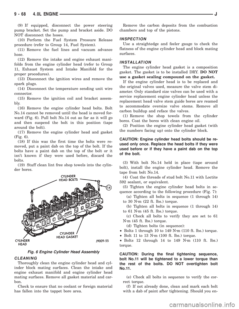
(16) Remove the engine cylinder head bolts. Bolt
No.14 cannot be removed until the head is moved for-
ward (Fig. 6). Pull bolt No.14 out as far as it will go
and then suspend the bolt in this position (tape
around the bolt).
(17) Remove the engine cylinder head and gasket
(Fig. 6).
(18) If this was the first time the bolts were re-
moved, put a paint dab on the top of the bolt. If the
bolts have a paint dab on the top of the bolt or it
isn't known if they were used before, discard the
bolts.
(19) Stuff clean lint free shop towels into the cylin-
der bores.
CLEANING
Thoroughly clean the engine cylinder head and cyl-
inder block mating surfaces. Clean the intake and
engine exhaust manifold and engine cylinder head
mating surfaces. Remove all gasket material and car-
bon.
Check to ensure that no coolant or foreign material
has fallen into the tappet bore area.Remove the carbon deposits from the combustion
chambers and top of the pistons.
INSPECTION
Use a straightedge and feeler gauge to check the
flatness of the engine cylinder head and block mating
surfaces.
INSTALLATION
The engine cylinder head gasket is a composition
gasket. The gasket is to be installed DRY.DO NOT
use a gasket sealing compound on the gasket.
If the engine cylinder head is to be replaced and
the original valves used, measure the valve stem di-
ameter. Only standard size valves can be used with a
service replacement engine cylinder head unless the
replacement head valve stem guide bores are reamed
to accommodate oversize valve stems. Remove all
carbon buildup and reface the valves.
(1) Remove the shop towels from the cylinder
bores. Coat the bores with clean engine oil.
(2) Position the engine cylinder head gasket (with
the numbers facing up) onto the cylinder block.
CAUTION: Engine cylinder head bolts should be re-
used only once. Replace the head bolts if they were
used before or if they have a paint dab on the top
of the bolt.
(3) With bolt No.14 held in place (tape around
bolt), install the engine cylinder head. Remove the
tape from bolt No.14.
(4) Coat the threads of stud bolt No.11 with Loctite
592 sealant, or equivalent.
(5) Tighten the engine cylinder head bolts in se-
quence according to the following procedure (Fig. 7):
(a) Tighten all bolts in sequence (1 through 14)
to 30 Nzm (22 ft. lbs.) torque.
(b) Tighten all bolts in sequence (1 through 14)
to 61 Nzm (45 ft. lbs.) torque.
(c) Check all bolts to verify they are set to 61
Nzm (45 ft. lbs.) torque.
(d) Tighten bolts (in sequence):
²Bolts 1 through 10 to 149 Nzm (110 ft. lbs.) torque.
²Bolt 11 to 13 Nzm (100 ft. lbs.) torque.
²Bolts 12 through 14 to 149 Nzm (110 ft. lbs.)
torque.
CAUTION: During the final tightening sequence,
bolt No.11 will be tightened to a lower torque than
the rest of the bolts. DO NOT overtighten bolt
No.11.
(e) Check all bolts in sequence to verify the cor-
rect torque.
(f) If not already done, clean and mark each bolt
with a dab of paint after tightening. Should you en-
Fig. 6 Engine Cylinder Head Assembly
9 - 68 4.0L ENGINEJ