1995 JEEP XJ tow
[x] Cancel search: towPage 427 of 2158
TURN SIGNAL AND HAZARD WARNING SYSTEMS
CONTENTS
page page
DIAGNOSIS............................. 3
GENERAL INFORMATION.................. 1SERVICE PROCEDURES................... 5
GENERAL INFORMATION
Following are general descriptions of the major
components in the XJ (Cherokee)/YJ (Wrangler)
model turn signal and hazard warning systems. Refer
to Group 8W - Wiring Diagrams for complete circuit
descriptions and diagrams.
TURN SIGNAL SYSTEM
With the ignition switch in the ON or ACCESSORY
position and the turn signal switch lever (YJ) or
multi-function switch control lever (XJ) moved up
(right turn) or down (left turn), the turn signal sys-
tem is activated.
When the turn signal system is activated, the se-
lected (right or left) turn signal indicator lamp, front
park/turn signal lamp and rear tail/stop/turn signal
lamp bulb filaments will flash. With the headlamp
switch in the OFF position, the turn and front side
marker lamps flash in unison. With the headlamp
switch in the ON position, the turn and front side
marker lamps flash alternately.
HAZARD WARNING SYSTEM
The hazard warning is activated by a switch button
located below the ignition lock cylinder (YJ) or on the
top of the steering column (XJ) between the steering
wheel and the instrument panel. The hazard warning
flasher (YJ) or combination flasher (XJ) receives bat-
tery feed at all times, and the system is functional
regardless of ignition switch position. The hazard
warning switch button is identified with a double
triangle. On YJ models, push the switch button in to
activate the hazard warning system and pull the
button out to turn system off. On XJ models, push in
on the switch button to latch the switch and activate
the hazard warning system, and push in on the
switch button again to unlatch the switch and turn
the system off.
When the hazard warning system is activated, all
(right and left) turn signal indicator, front park/turn
signal lamp and rear tail/stop/turn signal lamp bulb
filaments will flash.
TURN SIGNAL FLASHER (YJ ONLY)
The turn signal flasher is located in the fuseblock
module. It contains one fixed contact point and one
contact point attached to a flexible bimetal arm. The
contact points are normally closed. When a turn sig-
nal is activated, current flows through the flasher. As
current flows through the bimetal arm it heats and
flexes to pull the contact points open, stopping cur-
rent flow. As the bimetal arm cools it straightens,
until the contact points close and the cycle repeats.
The standard flasher is designed to handle the cur-
rent flow requirements of the factory installed light-
ing. If supplemental lighting is added to the turn
signal circuits such as when towing a trailer with
lights, the current flow through the flasher increases.
This causes the flash rate to increase. It is recom-
mended that the standard flasher be replaced with a
heavy-duty (hazard warning) flasher when supple-
mental lighting is added.
However, when a turn signal bulb fails with a stan-
dard flasher, the remaining bulbs in that circuit will
light, but not flash. This will give the driver an indi-
cation to check the turn signal bulbs. Because a
heavy-duty flasher has different internal circuitry, a
failed bulb will not prevent the remaining bulbs in
the circuit from flashing. Therefore, it is recom-
mended that an occasional visual inspection of exte-
rior turn signal lamp operation be performed when a
heavy-duty flasher is installed.
HAZARD WARNING FLASHER (YJ ONLY)
The hazard warning flasher is located in the fuse-
block module. The hazard warning flasher contains
two normally open contact points mounted to two
flexible arms. A bimetal strip is attached between the
two arms. When the hazard warning is activated,
current flows through the flasher. As the current
flows through the bimetal strip it heats and pulls the
flexible arms together until the contact points close,
JTURN SIGNAL AND HAZARD WARNING SYSTEMS 8J - 1
Page 428 of 2158
allowing current flow to the lamps. As the bimetal
strip cools, the contact points are pushed open and
the cycle repeats.
COMBINATION FLASHER (XJ ONLY)
The combination flasher functions as both the turn
signal and hazard warning flasher on XJ models. The
combination flasher is a smart relay that is located in
the relay center under the lower instrument panel
and inboard of the steering column. The combination
flasher can not be repaired. If faulty, it must be
replaced.
The combination flasher is designed to handle the
current flow requirements of the factory installed
lighting. If supplemental lighting is added to the turn
signal circuits such as when towing a trailer with
lights, the combination flasher will automatically
compensate. This allows the flash rate to remain the
same, regardless of electrical load increases. However,
if a bulb fails in the turn signal or hazard warning
circuits, the flash rate of the remaining bulbs in that
circuit will increase to 120 flashes per minute or
higher.
TURN SIGNAL/HAZARD WARNING SWITCH
(YJ ONLY)
The turn signal and hazard warning switches are
combined into a single unit mounted within the upper
steering column bowl and beneath the steering wheel.
The turn signal lever on the left side of the steering
column is moved up or down to select the right or left
turn signal switch position. The turn signals will only
operate with the ignition switch in the ACCESSORY
or ON position.
The hazard warning button on the right side of the
steering column is pushed in to turn the hazard
warning system on, or pulled out to turn the system
off. The hazard warning system will operate regard-
less of ignition switch position. The turn signal/haz-
ard warning switch can not be repaired. If faulty, the
entire unit must be replaced.
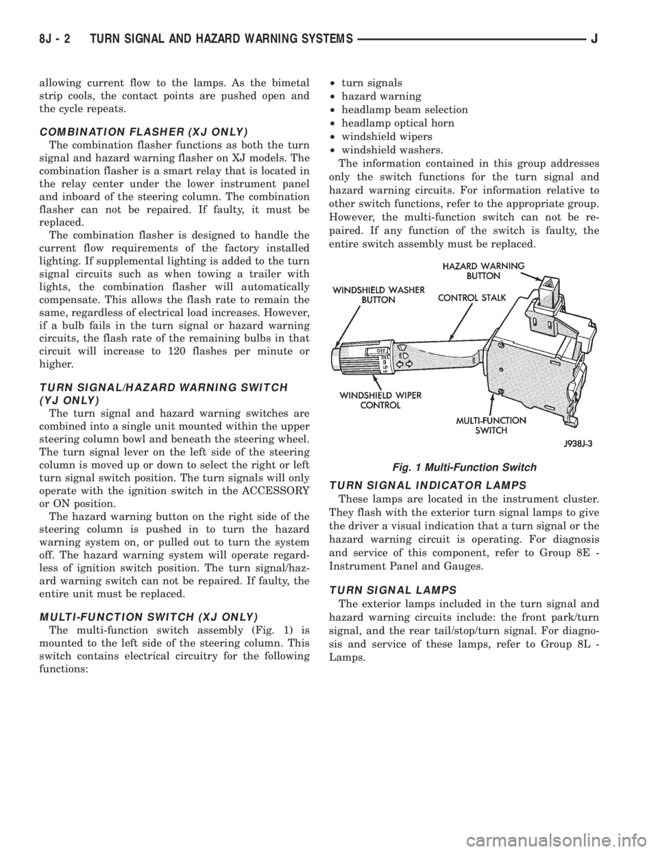
MULTI-FUNCTION SWITCH (XJ ONLY)
The multi-function switch assembly (Fig. 1) is
mounted to the left side of the steering column. This
switch contains electrical circuitry for the following
functions:²turn signals
²hazard warning
²headlamp beam selection
²headlamp optical horn
²windshield wipers
²windshield washers.
The information contained in this group addresses
only the switch functions for the turn signal and
hazard warning circuits. For information relative to
other switch functions, refer to the appropriate group.
However, the multi-function switch can not be re-
paired. If any function of the switch is faulty, the
entire switch assembly must be replaced.
TURN SIGNAL INDICATOR LAMPS
These lamps are located in the instrument cluster.
They flash with the exterior turn signal lamps to give
the driver a visual indication that a turn signal or the
hazard warning circuit is operating. For diagnosis
and service of this component, refer to Group 8E -
Instrument Panel and Gauges.
TURN SIGNAL LAMPS
The exterior lamps included in the turn signal and
hazard warning circuits include: the front park/turn
signal, and the rear tail/stop/turn signal. For diagno-
sis and service of these lamps, refer to Group 8L -
Lamps.
Fig. 1 Multi-Function Switch
8J - 2 TURN SIGNAL AND HAZARD WARNING SYSTEMSJ
Page 433 of 2158
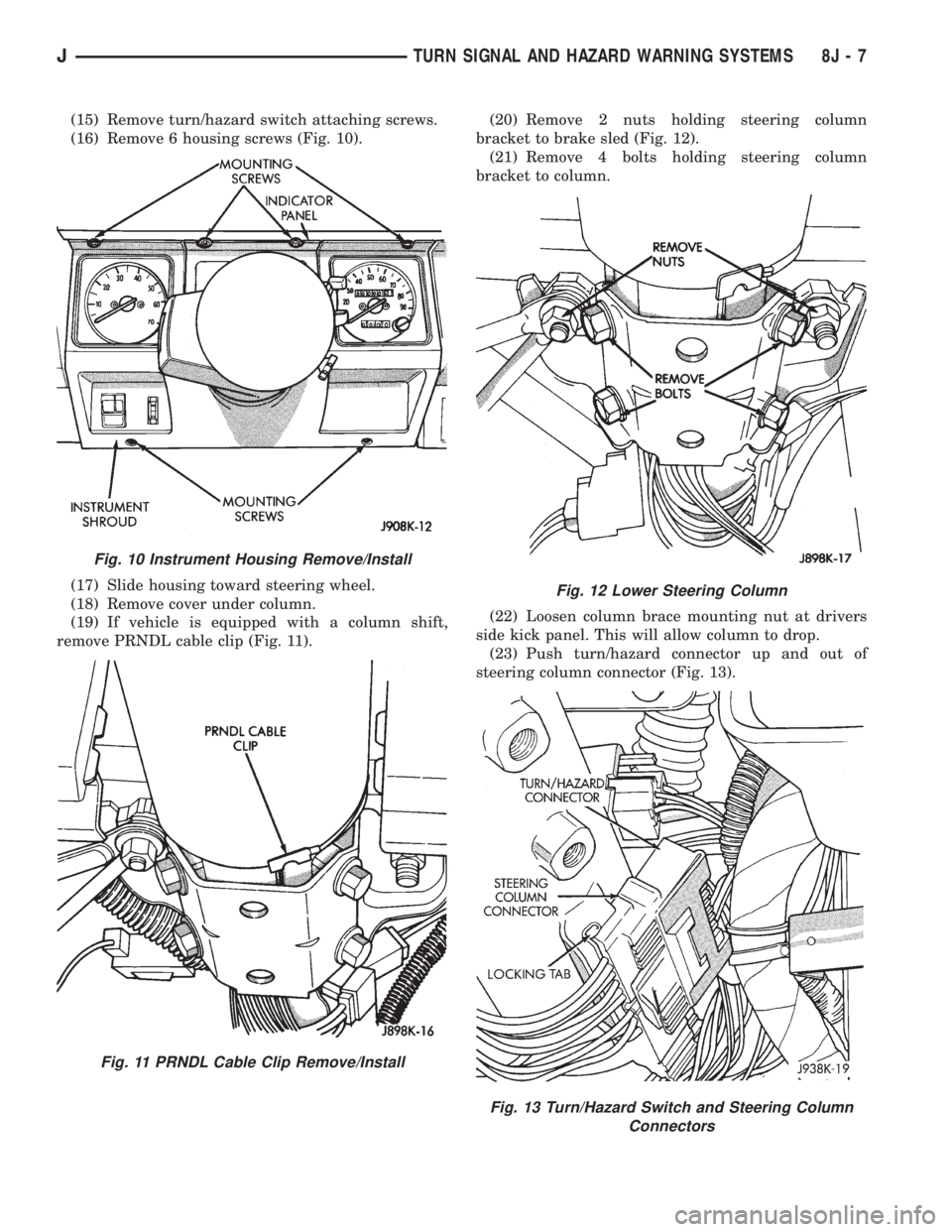
(15) Remove turn/hazard switch attaching screws.
(16) Remove 6 housing screws (Fig. 10).
(17) Slide housing toward steering wheel.
(18) Remove cover under column.
(19) If vehicle is equipped with a column shift,
remove PRNDL cable clip (Fig. 11).(20) Remove 2 nuts holding steering column
bracket to brake sled (Fig. 12).
(21) Remove 4 bolts holding steering column
bracket to column.
(22) Loosen column brace mounting nut at drivers
side kick panel. This will allow column to drop.
(23) Push turn/hazard connector up and out of
steering column connector (Fig. 13).
Fig. 10 Instrument Housing Remove/Install
Fig. 11 PRNDL Cable Clip Remove/Install
Fig. 12 Lower Steering Column
Fig. 13 Turn/Hazard Switch and Steering Column
Connectors
JTURN SIGNAL AND HAZARD WARNING SYSTEMS 8J - 7
Page 443 of 2158

(2) Reservoir filler neck is held in reservoir by a
grommet. Remove reservoir filler neck (Fig. 17) by
pulling sharply away from reservoir.
(3) Remove 2 reservoir mounting screws.
(4) Raise vehicle on hoist and remove left front in-
ner wheelhouse splash shield.
(5) Disconnect hose(s) from washer pump(s) and
drain solvent from reservoir into a clean container
for re-use.
(6) Disconnect wiring from pump(s) and fluid level
sensor (if equipped).
(7) Remove washer pumps from reservoir by pull-
ing out of grommets.
(8) To remove reservoir, slide slightly towards rear
of vehicle to release hook (Fig. 17) from inner fender
slot. Then lower front of reservoir and slide unit for-
ward to remove.(9) Reverse removal procedures to install. Use new
grommets when installing washer pumps.
Fig. 16 Washer Pumps (LHD)
Fig. 17 Washer Reservoir and Pumps (RHD)
JWIPER AND WASHER SYSTEMS - XJ 8K - 9
Page 454 of 2158
LIFTGATE WIPER MOTOR REMOVE/INSTALL
(1) Remove wiper arm from motor (see Liftgate
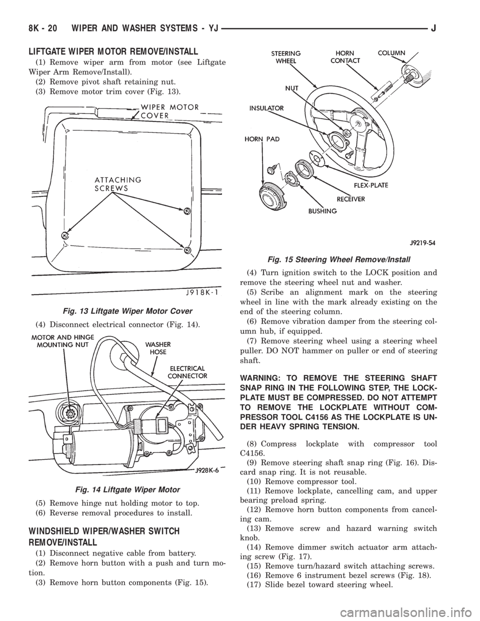
Wiper Arm Remove/Install).
(2) Remove pivot shaft retaining nut.
(3) Remove motor trim cover (Fig. 13).
(4) Disconnect electrical connector (Fig. 14).
(5) Remove hinge nut holding motor to top.
(6) Reverse removal procedures to install.
WINDSHIELD WIPER/WASHER SWITCH
REMOVE/INSTALL
(1) Disconnect negative cable from battery.
(2) Remove horn button with a push and turn mo-
tion.
(3) Remove horn button components (Fig. 15).(4) Turn ignition switch to the LOCK position and
remove the steering wheel nut and washer.
(5) Scribe an alignment mark on the steering
wheel in line with the mark already existing on the
end of the steering column.
(6) Remove vibration damper from the steering col-
umn hub, if equipped.
(7) Remove steering wheel using a steering wheel
puller. DO NOT hammer on puller or end of steering
shaft.
WARNING: TO REMOVE THE STEERING SHAFT
SNAP RING IN THE FOLLOWING STEP, THE LOCK-
PLATE MUST BE COMPRESSED. DO NOT ATTEMPT
TO REMOVE THE LOCKPLATE WITHOUT COM-
PRESSOR TOOL C4156 AS THE LOCKPLATE IS UN-
DER HEAVY SPRING TENSION.
(8) Compress lockplate with compressor tool
C4156.
(9) Remove steering shaft snap ring (Fig. 16). Dis-
card snap ring. It is not reusable.
(10) Remove compressor tool.
(11) Remove lockplate, cancelling cam, and upper
bearing preload spring.
(12) Remove horn button components from cancel-
ing cam.
(13) Remove screw and hazard warning switch
knob.
(14) Remove dimmer switch actuator arm attach-
ing screw (Fig. 17).
(15) Remove turn/hazard switch attaching screws.
(16) Remove 6 instrument bezel screws (Fig. 18).
(17) Slide bezel toward steering wheel.
Fig. 13 Liftgate Wiper Motor Cover
Fig. 14 Liftgate Wiper Motor
Fig. 15 Steering Wheel Remove/Install
8K - 20 WIPER AND WASHER SYSTEMS - YJJ
Page 486 of 2158
HEADLAMP SWITCHÐYJ
To remove or replace the headlamp switch, refer to
Group 8E, Instrument Panel and Gauges.
FOG LAMP SWITCH REPLACEMENTÐYJ
REMOVAL
The fog lamp switch is located on the instrument
panel at the right of the steering column. The fog
lamp circuit relay is located below the left headlamp.
(1) Disconnect the battery negative cable.
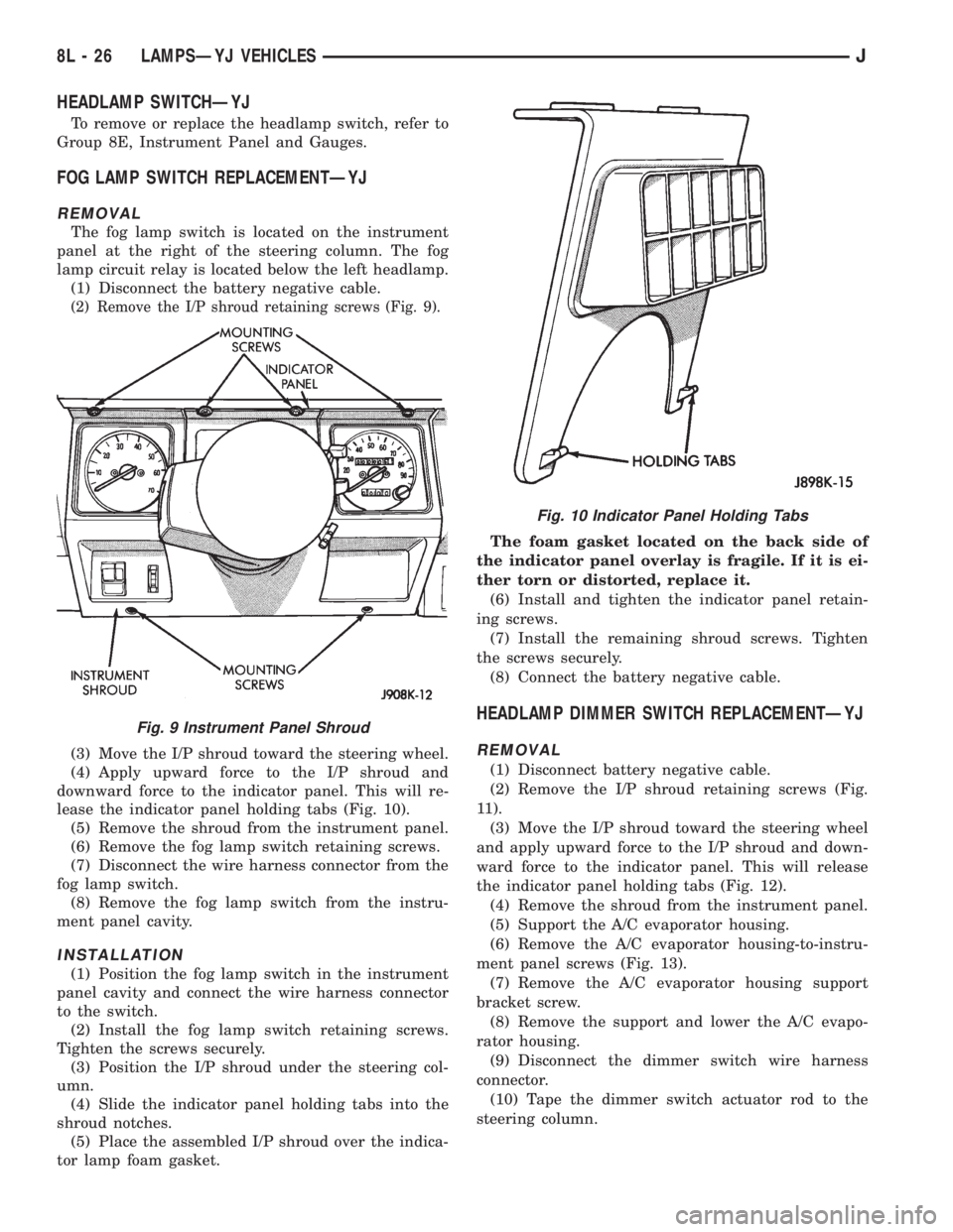
(2) Remove the I/P shroud retaining screws (Fig. 9).
(3) Move the I/P shroud toward the steering wheel.
(4) Apply upward force to the I/P shroud and
downward force to the indicator panel. This will re-
lease the indicator panel holding tabs (Fig. 10).
(5) Remove the shroud from the instrument panel.
(6) Remove the fog lamp switch retaining screws.
(7) Disconnect the wire harness connector from the
fog lamp switch.
(8) Remove the fog lamp switch from the instru-
ment panel cavity.
INSTALLATION
(1) Position the fog lamp switch in the instrument
panel cavity and connect the wire harness connector
to the switch.
(2) Install the fog lamp switch retaining screws.
Tighten the screws securely.
(3) Position the I/P shroud under the steering col-
umn.
(4) Slide the indicator panel holding tabs into the
shroud notches.
(5) Place the assembled I/P shroud over the indica-
tor lamp foam gasket.The foam gasket located on the back side of
the indicator panel overlay is fragile. If it is ei-
ther torn or distorted, replace it.
(6) Install and tighten the indicator panel retain-
ing screws.
(7) Install the remaining shroud screws. Tighten
the screws securely.
(8) Connect the battery negative cable.
HEADLAMP DIMMER SWITCH REPLACEMENTÐYJ
REMOVAL
(1) Disconnect battery negative cable.
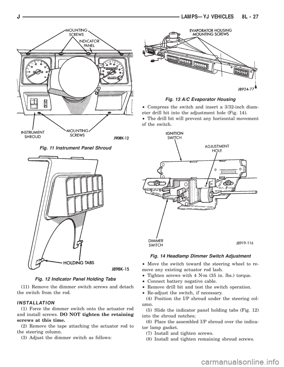
(2) Remove the I/P shroud retaining screws (Fig.
11).
(3) Move the I/P shroud toward the steering wheel
and apply upward force to the I/P shroud and down-
ward force to the indicator panel. This will release
the indicator panel holding tabs (Fig. 12).
(4) Remove the shroud from the instrument panel.
(5) Support the A/C evaporator housing.
(6) Remove the A/C evaporator housing-to-instru-
ment panel screws (Fig. 13).
(7) Remove the A/C evaporator housing support
bracket screw.
(8) Remove the support and lower the A/C evapo-
rator housing.
(9) Disconnect the dimmer switch wire harness
connector.
(10) Tape the dimmer switch actuator rod to the
steering column.
Fig. 9 Instrument Panel Shroud
Fig. 10 Indicator Panel Holding Tabs
8L - 26 LAMPSÐYJ VEHICLESJ
Page 487 of 2158
(11) Remove the dimmer switch screws and detach
the switch from the rod.
INSTALLATION
(1) Force the dimmer switch onto the actuator rod
and install screws.DO NOT tighten the retaining
screws at this time.
(2) Remove the tape attaching the actuator rod to
the steering column.
(3) Adjust the dimmer switch as follows:²Compress the switch and insert a 3/32-inch diam-
eter drill bit into the adjustment hole (Fig. 14).
²The drill bit will prevent any horizontal movement
of the switch.
²Move the switch toward the steering wheel to re-
move any existing actuator rod lash.
²Tighten screws with 4 Nzm (35 in. lbs.) torque.
²Connect battery negative cable.
²Remove drill bit and test the switch operation.
²Re-adjust the switch, if necessary.
(4) Position the I/P shroud under the steering col-
umn.
(5) Slide the indicator panel holding tabs (Fig. 12)
into the shroud notches;
(6) Place the assembled I/P shroud over the indica-
tor lamp gasket.
(7) Install and tighten screws.
(8) Install and tighten remaining shroud screws.
Fig. 11 Instrument Panel Shroud
Fig. 12 Indicator Panel Holding Tabs
Fig. 13 A/C Evaporator Housing
Fig. 14 Headlamp Dimmer Switch Adjustment
JLAMPSÐYJ VEHICLES 8L - 27
Page 497 of 2158
REAR WINDOW DEFOGGER
CONTENTS
page page
DIAGNOSIS............................. 1
GENERAL INFORMATION.................. 1SERVICE PROCEDURES................... 3
GENERAL INFORMATION
The electrically-heated rear window defogger is an
available option on XJ (Cherokee), and YJ (Wrangler)
models equipped with the hardtop roof option. Fol-
lowing are general descriptions of the major compo-
nents in the rear window defogger system. Refer to
Group 8W - Wiring Diagrams for complete circuit de-
scriptions and diagrams.
REAR WINDOW GLASS GRID
The heated rear window glass has two electrically-
conductive vertical bus bars and a series of horizon-
tal grid lines made of a silver-ceramic material,
which is baked on and bonded to the inside surface of
the glass. The grid lines and bus bars comprise a
parallel electrical circuit.
When the rear window defogger switch is placed in
the ON position, current is directed to the rear win-
dow grid lines through the bus bars. The grid lines
heat the rear window to clear the surface of fog or
snow. Circuit protection for the heated grid circuit is
provided by fuse 18 (XJ) or fuse 6 (YJ) in the fuse-
block module.
The grid lines and bus bars are highly resistant to
abrasion. However, it is possible for an open to occur
in an individual grid line resulting in no current flow
through the line. The grid lines can be damaged or
scraped off with sharp instruments. Care should be
taken in cleaning the glass or removing foreign ma-
terials, decals or stickers. Normal glass cleaning sol-
vents or hot water used with rags or toweling is
recommended.A repair kit is available to repair the grid lines and
bus bars, or to reinstall the heated glass pigtail
wires.
DEFOGGER SWITCH
The rear window defogger switch is mounted in the
instrument panel left of the steering column for XJ,
or right of the steering column for YJ. The switch cir-
cuit is protected by fuse 8 (XJ) or fuse 9 (YJ) in the
fuseblock module. Actuating the switch energizes the
relay and electronic timer. A light-emitting diode
(LED) in the switch (XJ), or a indicator lamp in the
switch (YJ), illuminates to indicate when the system
is turned on. The defogger switch can not be re-
paired. If faulty, the switch must be replaced.
DEFOGGER RELAY/TIMER
The defogger relay/timer is located in the relay cen-
ter on XJ models, or taped to the instrument panel
wiring harness behind the parking brake pedal in the
left cowl side area on YJ models. When the rear de-
fogger switch is actuated, the rear defogger relay is
energized. This causes current to flow through the
grid circuit for approximately 10 minutes, or until
the rear window defogger switch or ignition switch
are turned off.
DIAGNOSIS
SYSTEM TESTS
Electrically-heated rear window defogger operation
can be confirmed in the following manner:
(1) Turn the ignition switch to the ON position.
(2) Turn rear window defogger control switch ON.
(3) Monitor vehicle voltmeter. With the control
switch ON, a distinct needle deflection should be
noted.(4) The rear window defogger operation can be
checked by feeling the glass. A distinct difference in
temperature between the grid lines and adjacent
clear glass can be detected within 3 to 4 minutes of
operation.
(5) Using a DC voltmeter, contact terminal A (Fig.
1) (passenger side) with the negative lead, and termi-
JREAR WINDOW DEFOGGER 8N - 1