1995 JEEP XJ tow
[x] Cancel search: towPage 133 of 2158
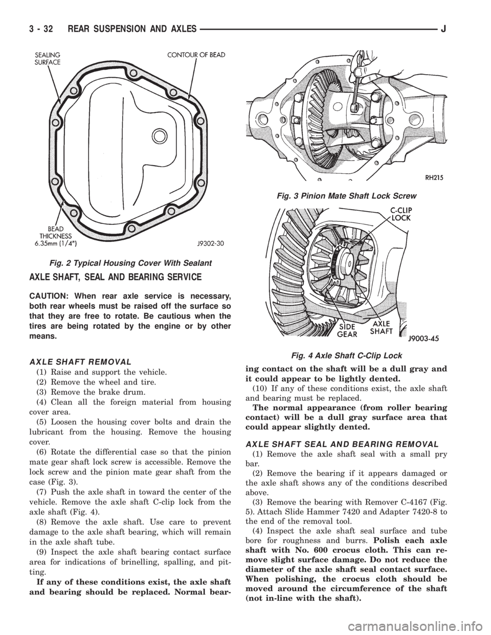
AXLE SHAFT, SEAL AND BEARING SERVICE
CAUTION: When rear axle service is necessary,
both rear wheels must be raised off the surface so
that they are free to rotate. Be cautious when the
tires are being rotated by the engine or by other
means.
AXLE SHAFT REMOVAL
(1) Raise and support the vehicle.
(2) Remove the wheel and tire.
(3) Remove the brake drum.
(4) Clean all the foreign material from housing
cover area.
(5) Loosen the housing cover bolts and drain the
lubricant from the housing. Remove the housing
cover.
(6) Rotate the differential case so that the pinion
mate gear shaft lock screw is accessible. Remove the
lock screw and the pinion mate gear shaft from the
case (Fig. 3).
(7) Push the axle shaft in toward the center of the
vehicle. Remove the axle shaft C-clip lock from the
axle shaft (Fig. 4).
(8) Remove the axle shaft. Use care to prevent
damage to the axle shaft bearing, which will remain
in the axle shaft tube.
(9) Inspect the axle shaft bearing contact surface
area for indications of brinelling, spalling, and pit-
ting.
If any of these conditions exist, the axle shaft
and bearing should be replaced. Normal bear-ing contact on the shaft will be a dull gray and
it could appear to be lightly dented.
(10) If any of these conditions exist, the axle shaft
and bearing must be replaced.
The normal appearance (from roller bearing
contact) will be a dull gray surface area that
could appear slightly dented.
AXLE SHAFT SEAL AND BEARING REMOVAL
(1) Remove the axle shaft seal with a small pry
bar.
(2) Remove the bearing if it appears damaged or
the axle shaft shows any of the conditions described
above.
(3) Remove the bearing with Remover C-4167 (Fig.
5). Attach Slide Hammer 7420 and Adapter 7420-8 to
the end of the removal tool.
(4) Inspect the axle shaft seal surface and tube
bore for roughness and burrs.Polish each axle
shaft with No. 600 crocus cloth. This can re-
move slight surface damage. Do not reduce the
diameter of the axle shaft seal contact surface.
When polishing, the crocus cloth should be
moved around the circumference of the shaft
(not in-line with the shaft).
Fig. 2 Typical Housing Cover With Sealant
Fig. 3 Pinion Mate Shaft Lock Screw
Fig. 4 Axle Shaft C-Clip Lock
3 - 32 REAR SUSPENSION AND AXLESJ
Page 148 of 2158
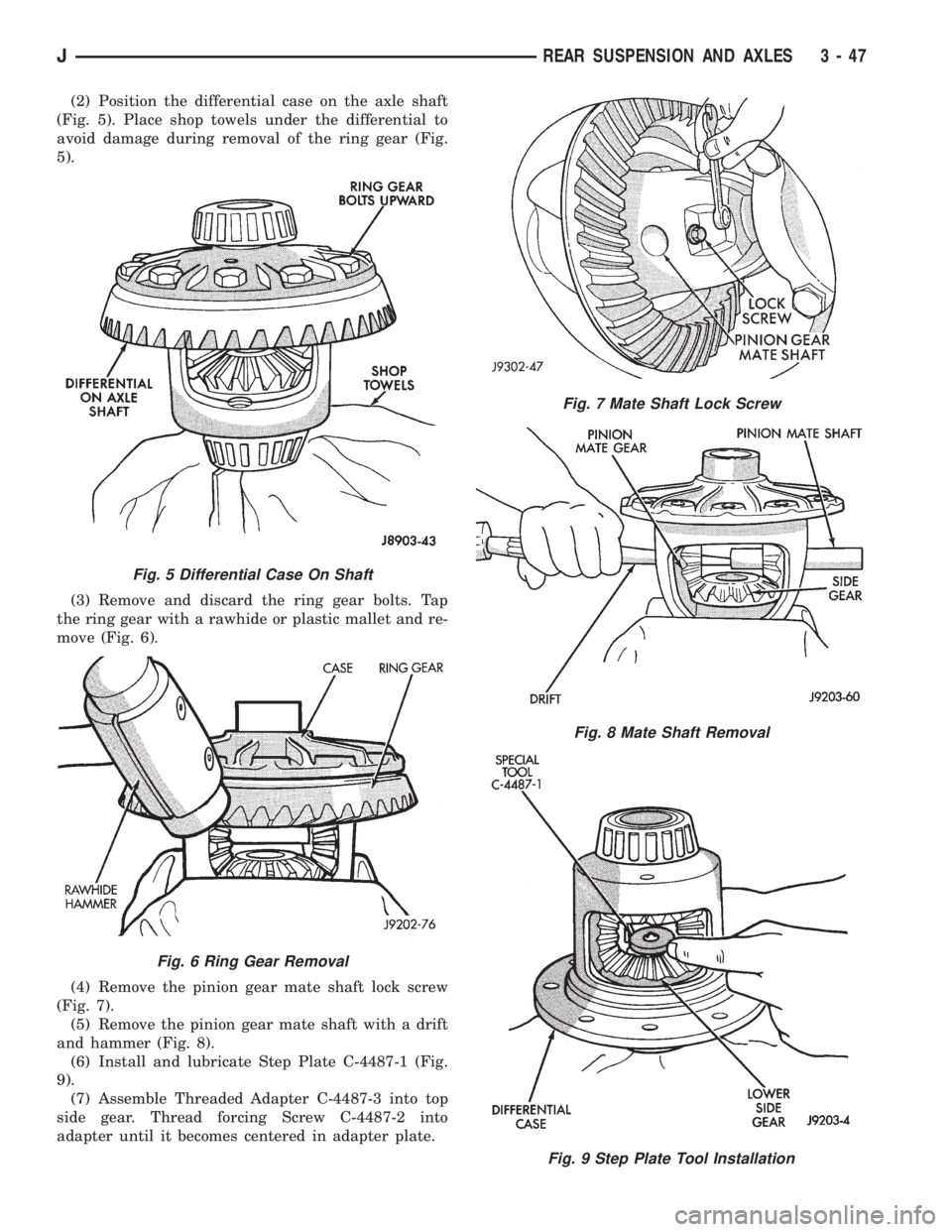
(2) Position the differential case on the axle shaft
(Fig. 5). Place shop towels under the differential to
avoid damage during removal of the ring gear (Fig.
5).
(3) Remove and discard the ring gear bolts. Tap
the ring gear with a rawhide or plastic mallet and re-
move (Fig. 6).
(4) Remove the pinion gear mate shaft lock screw
(Fig. 7).
(5) Remove the pinion gear mate shaft with a drift
and hammer (Fig. 8).
(6) Install and lubricate Step Plate C-4487-1 (Fig.
9).
(7) Assemble Threaded Adapter C-4487-3 into top
side gear. Thread forcing Screw C-4487-2 into
adapter until it becomes centered in adapter plate.
Fig. 7 Mate Shaft Lock Screw
Fig. 8 Mate Shaft Removal
Fig. 9 Step Plate Tool Installation
Fig. 5 Differential Case On Shaft
Fig. 6 Ring Gear Removal
JREAR SUSPENSION AND AXLES 3 - 47
Page 152 of 2158

AXLE SPECIFICATIONS
MODEL 35 AXLE
Axle Type...............................Semi-Floating Hypoid
Lubricant................SAE Thermally Stable 80W-90
Lubricant Trailer Tow.............Synthetic 75W-140
Lube Capacity..............................1.66 L (3.50 pts.)
Axle Ratio................................3.07, 3.55, 3.73, 4.10
Differential
Bearing Preload ............................0.1 mm (0.004 in.)
Side Gear Clearance ............0-0.15 mm (0-0.006 in.)
Ring Gear
Diameter .......................................19.2 cm (7.562 in.)
Backlash.........................0-0.15 mm (0.005-0.008 in.)
Pinion Std. Depth...................96.8 mm (3.813 in.)
Pinion Bearing Preload
Original Bearing ....................1-2Nzm (10-20 in. lbs.)
New Bearing .......................1.5-4Nzm (15-35 in. lbs.)
8 1/4 AXLE
Axle Type................................Semi-floating, hypoid
Lubricant...............................................SAE 75W-90
Lube Capacity................................2.08 L (4.4 pts.)
Axle Ratios.........................................3.07 3.55 4.10
Differential
Side Gear Clearance ..................0.12 mm (0.005 in.)
Case Flange Runout ..................0.07 mm (0.003 in.)
Bearing Preload ...........................95 Nzm (70 ft. lbs.)
Ring Gear
Diameter .......................................20.95 cm (8.25 in.)
Backlash....................0.12-0.20 mm (0.005-0.008 in.)
Runout .......................................0.127 mm (0.005 in.)
Pinion Bearing
Preload ....................................1-2 Nzm (10-20 in.lbs.)
TORQUE SPECIFICATIONS
XJ REAR SUSPENSION COMPONENTS
DESCRIPTION ................................................TORQUE
Shock Absorber
Upper Bolt ...................................23 Nzm (17 ft. lbs.)
Lower Nut ....................................62 Nzm (46 ft. lbs.)
Stabilizer Bar
Clamp Bolt ...................................54 Nzm (40 ft. lbs.)
Link Upper Bolt ............................12 Nzm (9 ft. lbs.)
Link Lower Nut ..........................74 Nzm (55 ft. lbs.)
Spring
U-Bolt Nut ...................................70 Nzm (52 ft. lbs.)
Front Pivot Bolt ......................148 Nzm (109 ft. lbs.)
Upper Shackle Bolt .................148 Nzm (109 ft. lbs.)
Lower Shackle Bolt ...................108 Nzm (80 ft. lbs.)
YJ REAR SUSPENSION COMPONENTS
DESCRIPTION ................................................TORQUE
Shock Absorber
Upper Nut ....................................61 Nzm (45 ft. lbs.)
Lower Nut ....................................61 Nzm (45 ft. lbs.)
Track Bar
Frame Bracket Nut.................142 Nzm (105 ft. lbs.)
Axle Bracket Nut ....................142 Nzm (105 ft. lbs.)Spring
U-Bolt Nut .................................122 Nzm (90 ft. lbs.)
Rear Shackle Bolts..................136 Nzm (100 ft. lbs.)
Front Pivot Bolt ......................142 Nzm (105 ft. lbs.)
MODEL 35 AXLE
DESCRIPTION ................................................TORQUE
Fill Hole Plug...........................34 Nzm (25 ft. lbs.)
Diff. Cover Bolt........................41 Nzm (30 ft. lbs.)
Bearing Cap Bolt.....................77 Nzm (57 ft. lbs.)
Pinion Nut...............292-427 Nzm (215-315 ft. lbs.)
Ring Gear Bolt.............95-122 Nzm (70-90 ft. lbs.)
RWAL/ABS Sensor Bolt.........24 Nzm (18. ft. lbs.)
8 1/4 AXLE
DESCRIPTION ................................................TORQUE
Diff. Cover Bolt........................47 Nzm (35 ft. lbs.)
Bearing Cap Bolt.....................95 Nzm (70 ft. lbs.)
Pinion Nut.............................285 Nzm (210 ft. lbs.)
Ring Gear Bolt.........................95 Nzm (70 ft. lbs.)
RWAL/ABS Sensor Bolt.........24 Nzm (18. ft. lbs.)
JREAR SUSPENSION AND AXLES 3 - 51
Page 163 of 2158
bubbles that are distributed throughout the hydrau-
lic system. This will make extra bleeding operations
necessary.
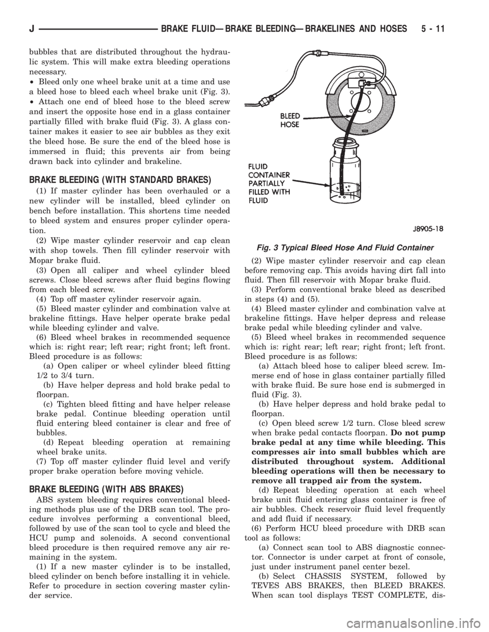
²Bleed only one wheel brake unit at a time and use
a bleed hose to bleed each wheel brake unit (Fig. 3).
²Attach one end of bleed hose to the bleed screw
and insert the opposite hose end in a glass container
partially filled with brake fluid (Fig. 3). A glass con-
tainer makes it easier to see air bubbles as they exit
the bleed hose. Be sure the end of the bleed hose is
immersed in fluid; this prevents air from being
drawn back into cylinder and brakeline.
BRAKE BLEEDING (WITH STANDARD BRAKES)
(1) If master cylinder has been overhauled or a
new cylinder will be installed, bleed cylinder on
bench before installation. This shortens time needed
to bleed system and ensures proper cylinder opera-
tion.
(2) Wipe master cylinder reservoir and cap clean
with shop towels. Then fill cylinder reservoir with
Mopar brake fluid.
(3) Open all caliper and wheel cylinder bleed
screws. Close bleed screws after fluid begins flowing
from each bleed screw.
(4) Top off master cylinder reservoir again.
(5) Bleed master cylinder and combination valve at
brakeline fittings. Have helper operate brake pedal
while bleeding cylinder and valve.
(6) Bleed wheel brakes in recommended sequence
which is: right rear; left rear; right front; left front.
Bleed procedure is as follows:
(a) Open caliper or wheel cylinder bleed fitting
1/2 to 3/4 turn.
(b) Have helper depress and hold brake pedal to
floorpan.
(c) Tighten bleed fitting and have helper release
brake pedal. Continue bleeding operation until
fluid entering bleed container is clear and free of
bubbles.
(d) Repeat bleeding operation at remaining
wheel brake units.
(7) Top off master cylinder fluid level and verify
proper brake operation before moving vehicle.
BRAKE BLEEDING (WITH ABS BRAKES)
ABS system bleeding requires conventional bleed-
ing methods plus use of the DRB scan tool. The pro-
cedure involves performing a conventional bleed,
followed by use of the scan tool to cycle and bleed the
HCU pump and solenoids. A second conventional
bleed procedure is then required remove any air re-
maining in the system.
(1) If a new master cylinder is to be installed,
bleed cylinder on bench before installing it in vehicle.
Refer to procedure in section covering master cylin-
der service.(2) Wipe master cylinder reservoir and cap clean
before removing cap. This avoids having dirt fall into
fluid. Then fill reservoir with Mopar brake fluid.
(3) Perform conventional brake bleed as described
in steps (4) and (5).
(4) Bleed master cylinder and combination valve at
brakeline fittings. Have helper depress and release
brake pedal while bleeding cylinder and valve.
(5) Bleed wheel brakes in recommended sequence
which is: right rear; left rear; right front; left front.
Bleed procedure is as follows:
(a) Attach bleed hose to caliper bleed screw. Im-
merse end of hose in glass container partially filled
with brake fluid. Be sure hose end is submerged in
fluid (Fig. 3).
(b) Have helper depress and hold brake pedal to
floorpan.
(c) Open bleed screw 1/2 turn. Close bleed screw
when brake pedal contacts floorpan.Do not pump
brake pedal at any time while bleeding. This
compresses air into small bubbles which are
distributed throughout system. Additional
bleeding operations will then be necessary to
remove all trapped air from the system.
(d) Repeat bleeding operation at each wheel
brake unit fluid entering glass container is free of
air bubbles. Check reservoir fluid level frequently
and add fluid if necessary.
(6) Perform HCU bleed procedure with DRB scan
tool as follows:
(a) Connect scan tool to ABS diagnostic connec-
tor. Connector is under carpet at front of console,
just under instrument panel center bezel.
(b) Select CHASSIS SYSTEM, followed by
TEVES ABS BRAKES, then BLEED BRAKES.
When scan tool displays TEST COMPLETE, dis-
Fig. 3 Typical Bleed Hose And Fluid Container
JBRAKE FLUIDÐBRAKE BLEEDINGÐBRAKELINES AND HOSES 5 - 11
Page 168 of 2158
(2) Disconnect brake lines at master cylinder and
combination valve.
(3) Remove nuts attaching master cylinder to
booster studs.
(4) Remove master cylinder.
(5) Remove cylinder cover and drain fluid.
(6) If two-piece master cylinder reservoir requires
service, refer to reservoir replacement procedure in
this section.
MASTER CYLINDER INSTALLATION (NON-ABS)
(1) Bleed master cylinder on bench before installa-
tion. Refer to procedure in this section.
(2) If new two-piece master cylinder is being in-
stalled, remove plastic protective sleeve from primary
piston shank. Also check condition of seal at rear of
cylinder body. Reposition seal if dislodged. Replace
seal if cut, or torn.
(3) Clean cylinder mounting surface of brake booster.
Use shop towel wetted with brake cleaner for this pur-
pose. Dirt, grease, or similar materials will prevent
proper cylinder seating and could result in vacuum leak.
(4) Slide master cylinder onto brake booster studs.
(5) Install nuts attaching master cylinder to booster
studs. Tighten nuts to 25 Nzm (220 in. lbs.) torque.
(6) Connect brakelines to master cylinder and com-
bination valve (Figs. 1 and 2).
(7) Fill and bleed brake system.
COMBINATION VALVE REPLACEMENT (NON-ABS)
The combination valve is not a repairable compo-
nent. The valve is serviced as an assembly whenever
diagnosis indicates replacement is necessary.
(1) Remove air cleaner cover and hose for access to
valve, if necessary.
(2) Disconnect differential pressure switch wire at
combination valve. Do not pull switch wire to discon-
nect. Unsnap connecter lock tabs to remove.
(3) Disconnect brakelines at combination valve and
remove valve.
(4) Connect brakelines to replacement valve. Start
line fittings by hand to avoid cross threading.
Tighten fittings snug but not to required torque at
this time.
(5) Connect wire to pressure differential switch.
(6) Bleed brakes.
(7) Tighten brakeline fittings to 18-24 Nzm
(160-210 in. lbs.) torque after bleeding.
MASTER CYLINDER OVERHAUL (4-CYLINDER
MODELS)
CYLINDER DISASSEMBLY
(1) Examine cylinder cover seal. Discard seal if
torn or distorted.
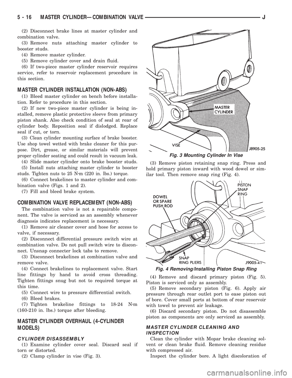
(2) Clamp cylinder in vise (Fig. 3).(3) Remove piston retaining snap ring. Press and
hold primary piston inward with wood dowel or sim-
ilar tool. Then remove snap ring (Fig. 4).
(4) Remove and discard primary piston (Fig. 5).
Piston is serviced only as assembly.
(5) Remove secondary piston (Fig. 6). Apply air
pressure through rear outlet port to ease piston out
of bore. Cover small ports at bottom of rear reservoir
with towel to prevent air leakage.
(6) Discard secondary piston. Do not disassemble
piston as components are only serviced as assembly.
MASTER CYLINDER CLEANING AND
INSPECTION
Clean the cylinder with Mopar brake cleaning sol-
vent or clean brake fluid. Remove cleaning residue
with compressed air.
Inspect the cylinder bore. A light discoloration of
Fig. 3 Mounting Cylinder In Vise
Fig. 4 Removing/Installing Piston Snap Ring
5 - 16 MASTER CYLINDERÐCOMBINATION VALVEJ
Page 172 of 2158
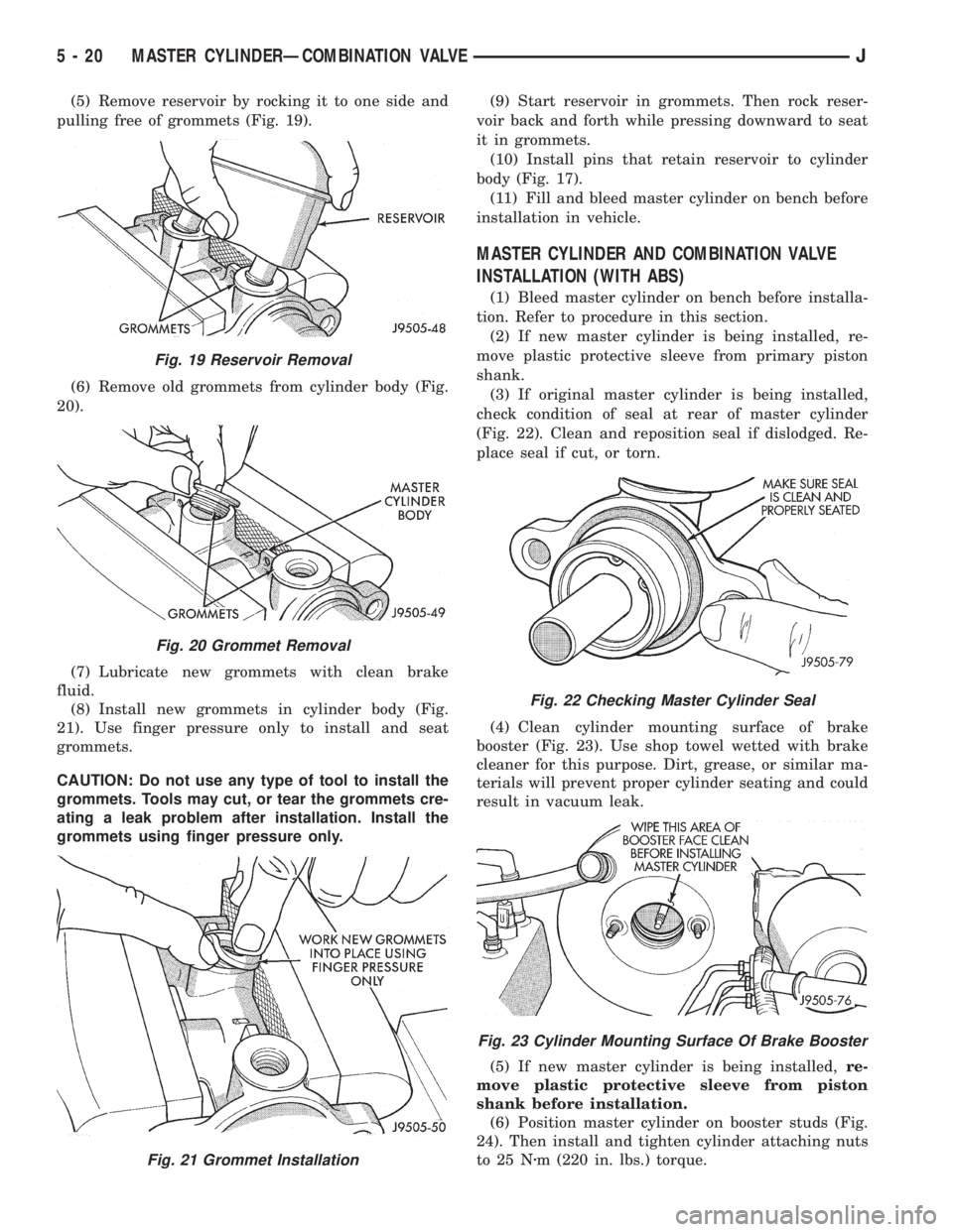
(5) Remove reservoir by rocking it to one side and
pulling free of grommets (Fig. 19).
(6) Remove old grommets from cylinder body (Fig.
20).
(7) Lubricate new grommets with clean brake
fluid.
(8) Install new grommets in cylinder body (Fig.
21). Use finger pressure only to install and seat
grommets.
CAUTION: Do not use any type of tool to install the
grommets. Tools may cut, or tear the grommets cre-
ating a leak problem after installation. Install the
grommets using finger pressure only.(9) Start reservoir in grommets. Then rock reser-
voir back and forth while pressing downward to seat
it in grommets.
(10) Install pins that retain reservoir to cylinder
body (Fig. 17).
(11) Fill and bleed master cylinder on bench before
installation in vehicle.
MASTER CYLINDER AND COMBINATION VALVE
INSTALLATION (WITH ABS)
(1) Bleed master cylinder on bench before installa-
tion. Refer to procedure in this section.
(2) If new master cylinder is being installed, re-
move plastic protective sleeve from primary piston
shank.
(3) If original master cylinder is being installed,
check condition of seal at rear of master cylinder
(Fig. 22). Clean and reposition seal if dislodged. Re-
place seal if cut, or torn.
(4) Clean cylinder mounting surface of brake
booster (Fig. 23). Use shop towel wetted with brake
cleaner for this purpose. Dirt, grease, or similar ma-
terials will prevent proper cylinder seating and could
result in vacuum leak.
(5) If new master cylinder is being installed,re-
move plastic protective sleeve from piston
shank before installation.
(6) Position master cylinder on booster studs (Fig.
24). Then install and tighten cylinder attaching nuts
to 25 Nzm (220 in. lbs.) torque.
Fig. 19 Reservoir Removal
Fig. 20 Grommet Removal
Fig. 21 Grommet Installation
Fig. 22 Checking Master Cylinder Seal
Fig. 23 Cylinder Mounting Surface Of Brake Booster
5 - 20 MASTER CYLINDERÐCOMBINATION VALVEJ
Page 180 of 2158
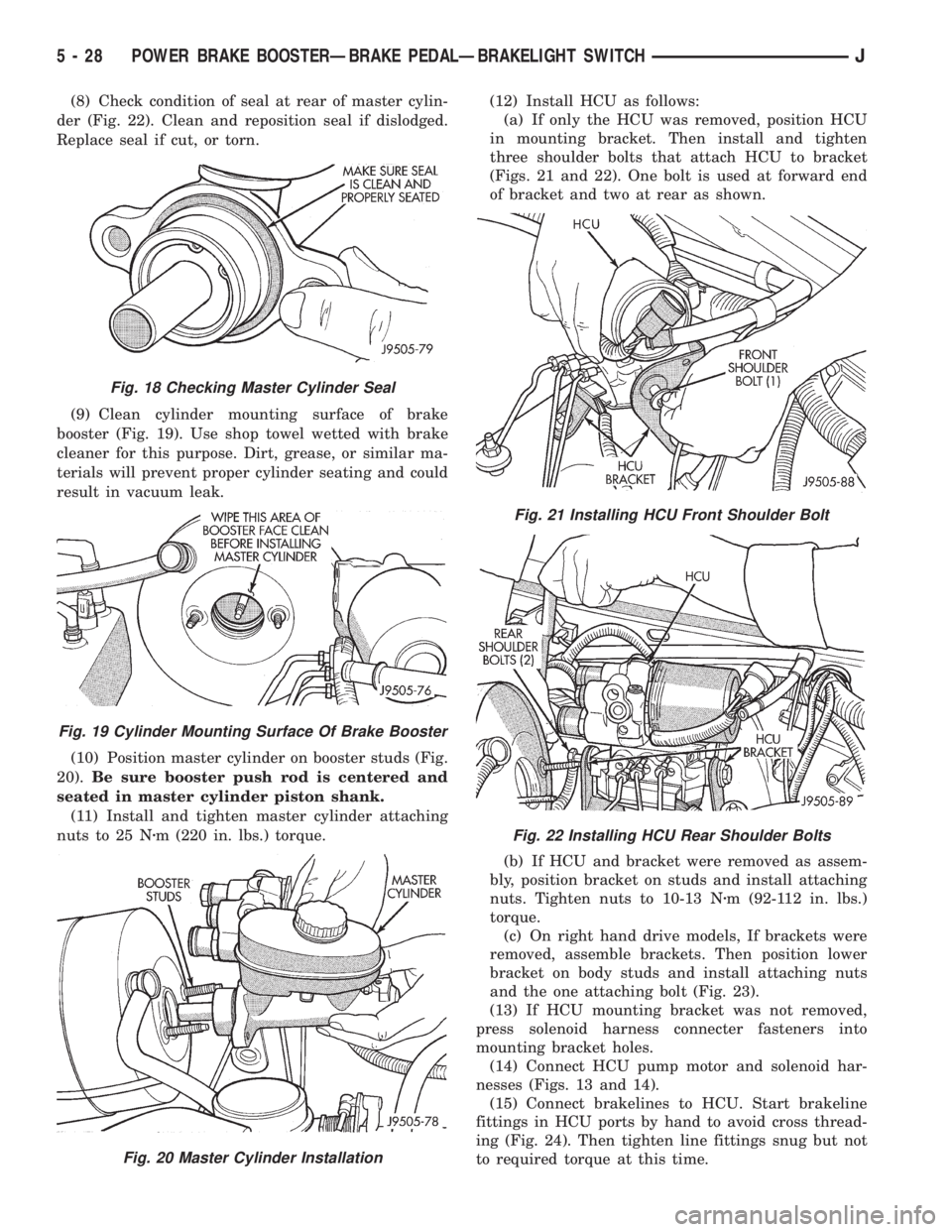
(8) Check condition of seal at rear of master cylin-
der (Fig. 22). Clean and reposition seal if dislodged.
Replace seal if cut, or torn.
(9) Clean cylinder mounting surface of brake
booster (Fig. 19). Use shop towel wetted with brake
cleaner for this purpose. Dirt, grease, or similar ma-
terials will prevent proper cylinder seating and could
result in vacuum leak.
(10) Position master cylinder on booster studs (Fig.
20).Be sure booster push rod is centered and
seated in master cylinder piston shank.
(11) Install and tighten master cylinder attaching
nuts to 25 Nzm (220 in. lbs.) torque.(12) Install HCU as follows:
(a) If only the HCU was removed, position HCU
in mounting bracket. Then install and tighten
three shoulder bolts that attach HCU to bracket
(Figs. 21 and 22). One bolt is used at forward end
of bracket and two at rear as shown.
(b) If HCU and bracket were removed as assem-
bly, position bracket on studs and install attaching
nuts. Tighten nuts to 10-13 Nzm (92-112 in. lbs.)
torque.
(c) On right hand drive models, If brackets were
removed, assemble brackets. Then position lower
bracket on body studs and install attaching nuts
and the one attaching bolt (Fig. 23).
(13) If HCU mounting bracket was not removed,
press solenoid harness connecter fasteners into
mounting bracket holes.
(14) Connect HCU pump motor and solenoid har-
nesses (Figs. 13 and 14).
(15) Connect brakelines to HCU. Start brakeline
fittings in HCU ports by hand to avoid cross thread-
ing (Fig. 24). Then tighten line fittings snug but not
to required torque at this time.
Fig. 18 Checking Master Cylinder Seal
Fig. 19 Cylinder Mounting Surface Of Brake Booster
Fig. 20 Master Cylinder Installation
Fig. 21 Installing HCU Front Shoulder Bolt
Fig. 22 Installing HCU Rear Shoulder Bolts
5 - 28 POWER BRAKE BOOSTERÐBRAKE PEDALÐBRAKELIGHT SWITCHJ
Page 182 of 2158
(11) Remove nuts attaching booster to passenger
compartment side of dash panel.
(12) In engine compartment, slide booster studs
out of dash panel, tilt booster upward, and remove
booster from engine compartment.
(13) Remove dash seal from booster.
(14) If booster is only being removed for access to
other components, cover booster front opening with
clean shop towel.
POWER BRAKE BOOSTER INSTALLATION (XJ
WITHOUT ABS)
(1) If original booster is being installed, test check
valve with vacuum tool before booster installation.
Replace check valve if it will not hold vacuum.
(2) Install dash seal on booster.
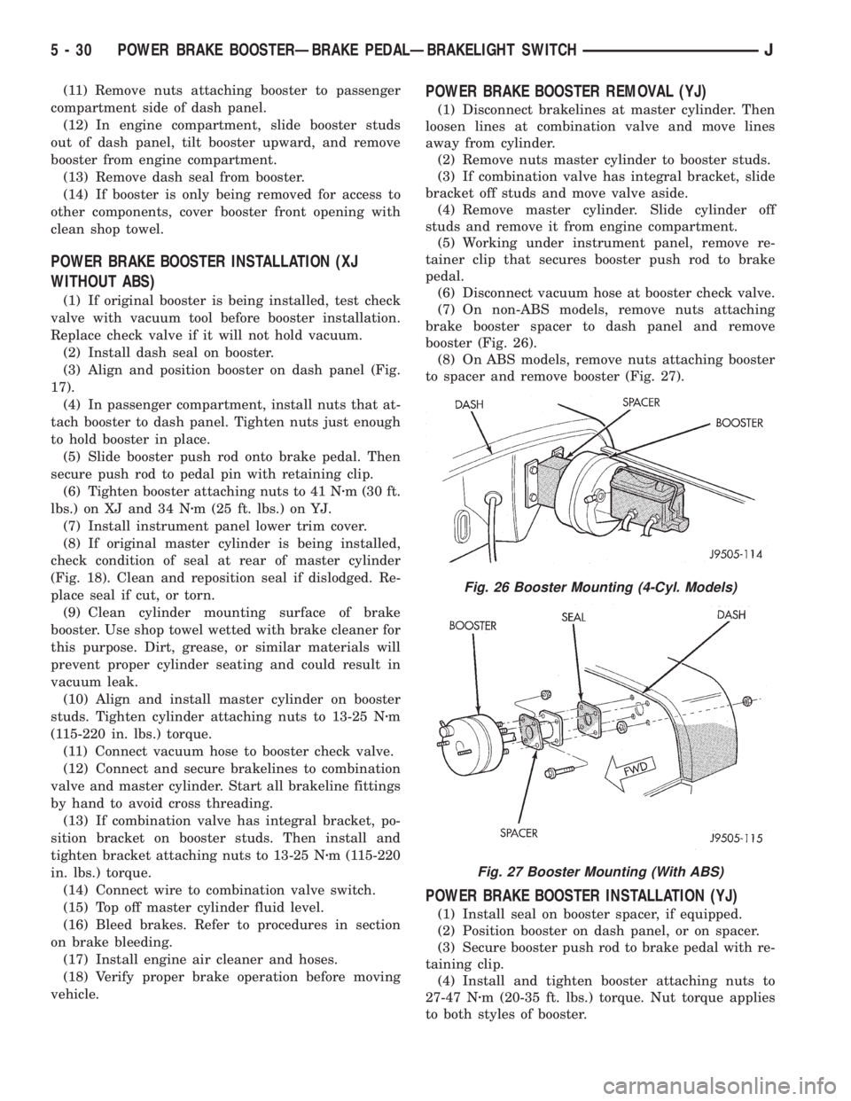
(3) Align and position booster on dash panel (Fig.
17).
(4) In passenger compartment, install nuts that at-
tach booster to dash panel. Tighten nuts just enough
to hold booster in place.
(5) Slide booster push rod onto brake pedal. Then
secure push rod to pedal pin with retaining clip.
(6) Tighten booster attaching nuts to 41 Nzm (30 ft.
lbs.) on XJ and 34 Nzm (25 ft. lbs.) on YJ.
(7) Install instrument panel lower trim cover.
(8) If original master cylinder is being installed,
check condition of seal at rear of master cylinder
(Fig. 18). Clean and reposition seal if dislodged. Re-
place seal if cut, or torn.
(9) Clean cylinder mounting surface of brake
booster. Use shop towel wetted with brake cleaner for
this purpose. Dirt, grease, or similar materials will
prevent proper cylinder seating and could result in
vacuum leak.
(10) Align and install master cylinder on booster
studs. Tighten cylinder attaching nuts to 13-25 Nzm
(115-220 in. lbs.) torque.
(11) Connect vacuum hose to booster check valve.
(12) Connect and secure brakelines to combination
valve and master cylinder. Start all brakeline fittings
by hand to avoid cross threading.
(13) If combination valve has integral bracket, po-
sition bracket on booster studs. Then install and
tighten bracket attaching nuts to 13-25 Nzm (115-220
in. lbs.) torque.
(14) Connect wire to combination valve switch.
(15) Top off master cylinder fluid level.
(16) Bleed brakes. Refer to procedures in section
on brake bleeding.
(17) Install engine air cleaner and hoses.
(18) Verify proper brake operation before moving
vehicle.
POWER BRAKE BOOSTER REMOVAL (YJ)
(1) Disconnect brakelines at master cylinder. Then
loosen lines at combination valve and move lines
away from cylinder.
(2) Remove nuts master cylinder to booster studs.
(3) If combination valve has integral bracket, slide
bracket off studs and move valve aside.
(4) Remove master cylinder. Slide cylinder off
studs and remove it from engine compartment.
(5) Working under instrument panel, remove re-
tainer clip that secures booster push rod to brake
pedal.
(6) Disconnect vacuum hose at booster check valve.
(7) On non-ABS models, remove nuts attaching
brake booster spacer to dash panel and remove
booster (Fig. 26).
(8) On ABS models, remove nuts attaching booster
to spacer and remove booster (Fig. 27).
POWER BRAKE BOOSTER INSTALLATION (YJ)
(1) Install seal on booster spacer, if equipped.
(2) Position booster on dash panel, or on spacer.
(3) Secure booster push rod to brake pedal with re-
taining clip.
(4) Install and tighten booster attaching nuts to
27-47 Nzm (20-35 ft. lbs.) torque. Nut torque applies
to both styles of booster.
Fig. 26 Booster Mounting (4-Cyl. Models)
Fig. 27 Booster Mounting (With ABS)
5 - 30 POWER BRAKE BOOSTERÐBRAKE PEDALÐBRAKELIGHT SWITCHJ