1995 JEEP XJ tow
[x] Cancel search: towPage 498 of 2158
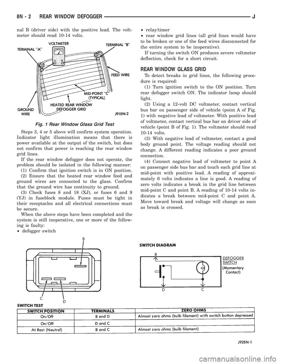
nal B (driver side) with the positive lead. The volt-
meter should read 10-14 volts.
Steps 3, 4 or 5 above will confirm system operation.
Indicator light illumination means that there is
power available at the output of the switch, but does
not confirm that power is reaching the rear window
grid lines.
If the rear window defogger does not operate, the
problem should be isolated in the following manner:
(1) Confirm that ignition switch is in ON position.
(2) Ensure that the heated rear window feed and
ground wires are connected to the glass. Confirm
that the ground wire has continuity to ground.
(3) Check fuses 8 and 18 (XJ), or fuses 6 and 9
(YJ) in fuseblock module. Fuses must be tight in
their receptacles and all electrical connections must
be secure.
When the above steps have been completed and the
system is still inoperative, one or more of the follow-
ing is faulty:
²defogger switch²relay/timer
²rear window grid lines (all grid lines would have
to be broken or one of the feed wires disconnected for
the entire system to be inoperative).
If turning the switch ON produces severe voltmeter
deflection, check for a short circuit.
REAR WINDOW GLASS GRID
To detect breaks in grid lines, the following proce-
dure is required:
(1) Turn ignition switch to the ON position. Turn
rear defogger switch ON. The indicator lamp should
light.
(2) Using a 12-volt DC voltmeter, contact vertical
bus bar on passenger side of vehicle (point A of Fig.
1) with negative lead of voltmeter. With positive lead
of voltmeter, contact vertical bus bar on driver side of
vehicle (point B of Fig. 1). The voltmeter should read
10-14 volts.
(3) With negative lead of voltmeter, contact a good
body ground point. The voltage reading should not
change. A different reading indicates a poor ground
connection.
(4) Connect negative lead of voltmeter to point A
on passenger side bus bar and touch each grid line at
mid-point with positive lead. A reading of approxi-
mately 6 volts indicates a line is good. A reading of
zero volts indicates a break in the grid line between
mid-point C and point B. A reading of 10-14 volts in-
dicates a break between mid-point C and point A.
Move toward break and voltage will change as soon
as break is crossed.
Fig. 1 Rear Window Glass Grid Test
8N - 2 REAR WINDOW DEFOGGERJ
Page 500 of 2158
(9) Allow epoxy to cure 24 hours at room tempera-
ture or use heat gun with a 260É-371ÉC (500É-700ÉF)
range for 15 minutes. Hold gun approximately
254mm (10 inches) from repaired area.
(10) After conductive epoxy is properly cured re-
move wedge or clamp from terminal or pigtail and
check operation of rear window defogger. Do not at-
tach connectors until curing is complete.
DEFOGGER SWITCH REMOVE/INSTALL
XJ MODELS
(1) Remove the instrument cluster bezel. Refer to
Group 8E - Instrument Panel and Gauges for proce-
dure.
(2) Remove the switch housing panel.
(3) Unplug the switch connector. Slightly depress
the switch mounting tabs and remove the switch.
(4) Reverse removal procedures to install.
YJ MODELS
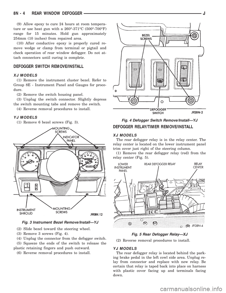
(1) Remove 6 bezel screws (Fig. 3).
(2) Slide bezel toward the steering wheel.
(3) Remove 3 screws (Fig. 4).
(4) Unplug the connector from the defogger switch.
(5) Squeeze the ends of the switch to release the
plastic retaining fingers and push outward.
(6) Reverse removal procedures to install.
DEFOGGER RELAY/TIMER REMOVE/INSTALL
XJ MODELS
The rear defogger relay is in the relay center. The
relay center is located on the lower instrument panel
trim cover just right of the steering column.
(1) Remove the rear defogger relay (red) from the
relay center (Fig. 5).
(2) Reverse removal procedures to install.
YJ MODELS
The rear defogger relay is located behind the park-
ing brake pedal in the left cowl side area. Unplug re-
lay from connector and replace with new relay. Be
certain that relay is taped back into place on harness
with plastic cover facing up and terminals facing
down.
Fig. 3 Instrument Bezel Remove/InstallÐYJ
Fig. 4 Defogger Switch Remove/InstallÐYJ
Fig. 5 Rear Defogger RelayÐXJ
8N - 4 REAR WINDOW DEFOGGERJ
Page 501 of 2158
POWER LOCKS
CONTENTS
page page
DIAGNOSIS............................. 2
GENERAL INFORMATION.................. 1SERVICE PROCEDURES................... 8
GENERAL INFORMATION
Power locks are optional equipment on XJ (Chero-
kee) models. Power windows and the keyless entry
system are included on vehicles equipped with the
power lock option. All doors and the liftgate can be
locked and unlocked electrically by operating the
switch on either front door panel, or by operating the
lock and unlock buttons of the remote keyless entry
transmitter. The power lock and keyless entry sys-
tems operate with battery power supplied indepen-
dent of the ignition switch.
Following are general descriptions of the major
components in the power lock system. Refer to Group
8W - Wiring Diagrams for complete circuit descrip-
tions and diagrams. Refer to the owner's manual for
more information on the features and use of these
systems.
POWER LOCK SWITCH
The power locks are controlled by a two-way switch
mounted on the trim panel of each front door. The
switch controls battery feed to the lock and unlock
relays. The door lock switches can not be repaired. If
faulty, the entire switch must be replaced.
POWER LOCK/UNLOCK RELAYS
The power lock and unlock relays are located in the
relay center. The relay center is located on the lower
instrument panel reinforcement behind the lower in-
strument panel and just right of the steering column.
The relays respond to inputs from the power lock
switches and the keyless entry module by sending
the correct battery and ground feeds to the lock mo-
tors. The lock and unlock relays can not be repaired.
If faulty, they must be replaced.
POWER LOCK MOTOR
The locks are actuated by a reversible motor
mounted within each door. The motor direction iscontrolled by the battery and ground feeds from the
power lock/unlock relays. The motor can not be re-
paired. If faulty, the entire motor must be replaced.
KEYLESS ENTRY TRANSMITTER
The keyless entry transmitter is equipped with two
buttons labeled Lock and Unlock. It is also designed
to serve as a key fob and is equipped with a key ring.
Each transmitter has a different vehicle access code,
which must be programmed into the memory of the
keyless entry module in the vehicle in order to oper-
ate the locks. The operating range of the infrared
transmitter signal is up to 4.75 meters (15 feet) from
the receiver.
The transmitter operates on two CR1616 3-volt (or
equivalent) batteries. Typical battery life is from one
to two years.
KEYLESS ENTRY MODULE
The keyless entry module is mounted in a housing
on the headliner near the windshield between the
sunvisors, or inside and towards the rear of the over-
head console (if equipped). This module contains the
keyless entry receiver and program logic for the key-
less entry system.
The keyless entry module has a memory function
to retain the vehicle access code of at least one, and
up to four transmitters. The module receives input
from the remote keyless entry transmitter. In re-
sponse to that input, it is programmed to control out-
puts to the lock and unlock relays. The module can
not be repaired and, if faulty, must be replaced.
JPOWER LOCKS 8P - 1
Page 510 of 2158
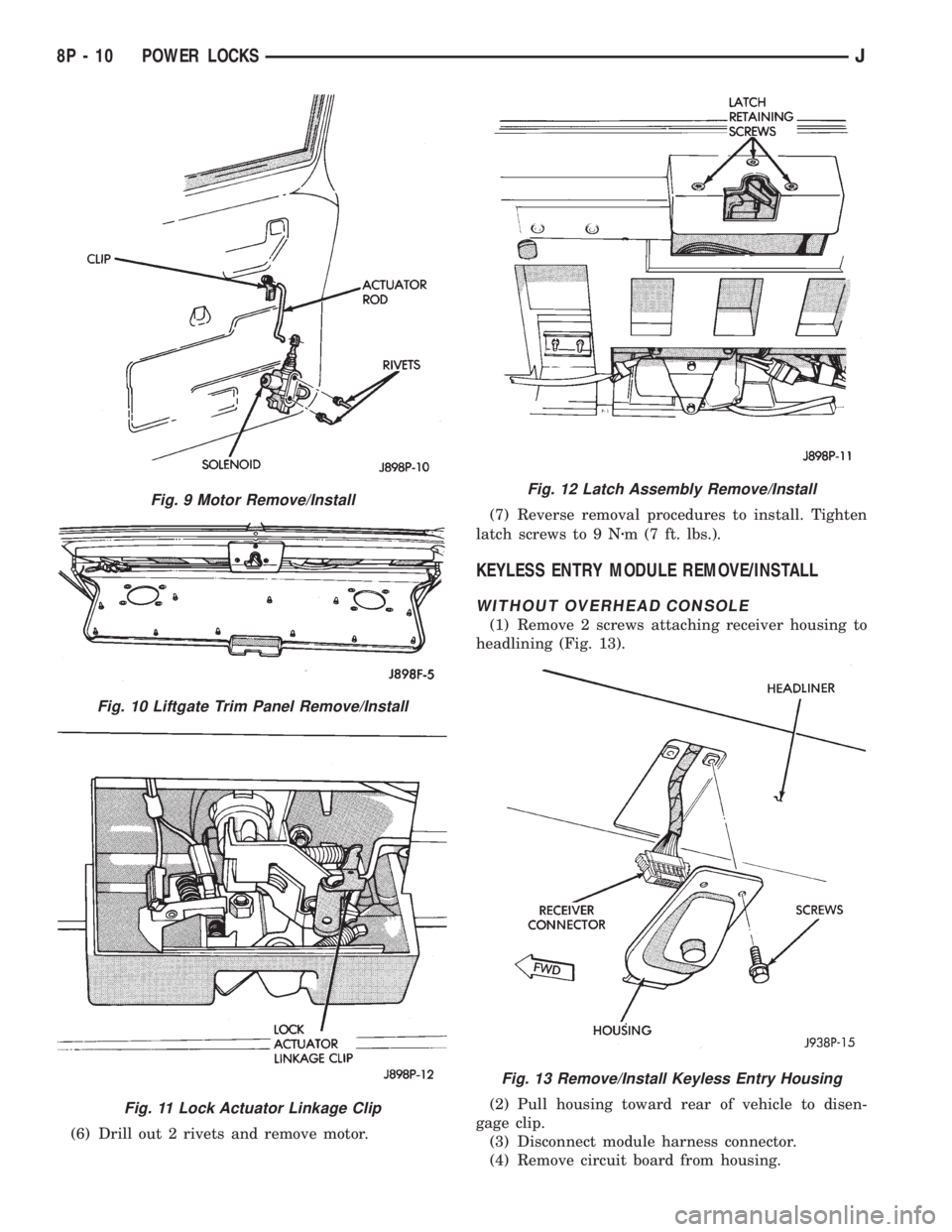
(6) Drill out 2 rivets and remove motor.(7) Reverse removal procedures to install. Tighten
latch screws to 9 Nzm (7 ft. lbs.).
KEYLESS ENTRY MODULE REMOVE/INSTALL
WITHOUT OVERHEAD CONSOLE
(1) Remove 2 screws attaching receiver housing to
headlining (Fig. 13).
(2) Pull housing toward rear of vehicle to disen-
gage clip.
(3) Disconnect module harness connector.
(4) Remove circuit board from housing.
Fig. 9 Motor Remove/Install
Fig. 10 Liftgate Trim Panel Remove/Install
Fig. 11 Lock Actuator Linkage Clip
Fig. 12 Latch Assembly Remove/Install
Fig. 13 Remove/Install Keyless Entry Housing
8P - 10 POWER LOCKSJ
Page 543 of 2158
WIRING DIAGRAMS
CONTENTS
page page
8W-01 GENERAL INFORMATIONÐWIRING
DIAGRAMS.................... 8W-01-1
8W-10 FUSE/FUSE BLOCK........... 8W-10-1
8W-11 POWER DISTRIBUTION........ 8W-11-1
8W-15 GROUND DISTRIBUTION....... 8W-15-1
8W-20 CHARGING SYSTEM.......... 8W-20-1
8W-21 STARTING SYSTEM........... 8W-21-1
8W-30 FUEL/IGNITION.............. 8W-30-1
8W-31 TRANSMISSION CONTROLS.... 8W-31-1
8W-32 ANTI-LOCK BRAKES.......... 8W-32-1
8W-33 VEHICLE SPEED CONTROL..... 8W-33-1
8W-40 INSTRUMENT CLUSTER....... 8W-40-1
8W-41 HORN/CIGAR LIGHTER......... 8W-41-1
8W-42 AIR CONDITIONING/HEATER.... 8W-42-1
8W-44 INTERIOR LIGHTING.......... 8W-44-1
8W-47 AUDIO SYSTEM.............. 8W-47-18W-48 HEATED REAR WINDOW....... 8W-48-1
8W-49 OVERHEAD CONSOLE......... 8W-49-1
8W-50 FRONT LIGHTING............. 8W-50-1
8W-51 REAR LIGHTING............. 8W-51-1
8W-52 TURN SIGNALS.............. 8W-52-1
8W-53 WIPERS..................... 8W-53-1
8W-54 TRAILER TOW................ 8W-54-1
8W-60 POWER WINDOWS.......... 8W-60-1
8W-61 POWER DOOR LOCKS......... 8W-61-1
8W-62 POWER MIRRORS............ 8W-62-1
8W-63 POWER SEAT................ 8W-63-1
8W-70 SPLICE INFORMATION........ 8W-70-1
8W-80 CONNECTOR PIN OUTS....... 8W-80-1
8W-90 CONNECTOR LOCATIONS...... 8W-90-1
8W-95 SPLICE LOCATIONS........... 8W-95-1
HOW TO USE THIS GROUP
The purpose of this group is to show the electrical
circuits in a clear, simple fashion and to make trou-
bleshooting easier. Components that work together
are shown together. All electrical components used in
a specific system are shown on one diagram. The feed
for a system is shown at the top of the page. All
wires, connectors, splices, and components are shown
in the flow of current to the bottom of the page. Wir-
ing which is not part of the circuit represented is ref-
erenced to another page/section, where the complete
circuit is shown. In addition, all switches, compo-
nents, and modules are shown in theat rest posi-
tion with the doors closed and the key removed
from the ignition.
If a component is part of several different circuits,
it is shown in the diagram for each. For example, the
headlamp switch is the main part of the exterior
lighting, but it also affects the interior lighting and
the chime warning system.
It is important to realize that no attempt is
made on the diagrams to represent components
and wiring as they appear on the vehicle. For
example, a short piece of wire is treated the
same as a long one. In addition, switches and
other components are shown as simply as pos-
sible, with regard to function only.
The wiring diagram show circuits for all wheel-
bases. If there is a difference in systems or compo-
nents between wheel-bases, an identifier is placed
next to the component.
SECTION IDENTIFICATION
Sections in Group 8W are organized by sub-sys-
tems. The sections contain circuit operation descrip-
tions, helpful information, and system diagrams. The
intention is to organize information by system, con-
sistently from year to year.
CONNECTOR LOCATIONS
Section 8W-90 contains Connector Location illus-
trations. The illustrations contain the connector
number and component identification. Connector Lo-
cation charts in Section 8W-90 reference the illustra-
tion number for components and connectors.
Section 8W-80 shows each connector and the cir-
cuits involved with that connector. The connectors
are identified using the number on the Diagram
pages.
SPLICE LOCATIONS
Splice Location charts in Section 8W-70 show the
entire splice, and provide references to other sections
the splice serves.
Section 8W-95 contains illustrations that show the
general location of the splices in each harness. The
illustrations show the splice by number, and provide
a written location.
JWIRING DIAGRAMSÐXJ VEHICLES 8W - 1 - 1
Page 677 of 2158
REAR LIGHTING
TAIL LAMPS AND REAR LICENSE PLATE LAMPS
Circuit A3 from fuse 5 in the Power Distribution
Center (PDC) connects to a bus bar in the fuse block
which feeds circuit L7. Fuse 15 in the fuse block pro-
tects circuit L7.
The headlamp switch has three positions: ON,
PARK (parking lamps) and OFF, plus a dimmer
switch. When the headlamp switch is in the PARK or
ON position, the switch connects circuit L7 to circuit
L90. From the headlamp switch, circuit L90 branches
to power the front parking lamps and rear tail
lamps, side marker lamps, and rear license plate
lamps.
GROUND CIRCUIT
Circuit Z1 provides a ground for the parking lamps,
tail lamps, and rear license plate lamps.
HELPFUL INFORMATION
²If the vehicle is equipped with factory installed
trailer tow, circuit L90 splices to the trailer tow har-
ness.
²Check fuse 5 in PDC.
²Check fuse 15 in the fuse block.
²When the headlamp switch is in the PARK or ON
position, circuit L7 also connects to circuit E2. Cir-
cuit E2 continues through fuse 19 in the fuse block.
Circuit E2 powers the illumination lamps.
STOP LAMPS AND CHMSL LAMPS
Circuit L9 from fuse 4 in the Power Distribution
Center (PDC) connects to the stop lamp switch.
When the operator depresses the brake pedal, the
stop lamp switch closes and connects circuit L9 to
circuit L50. Circuit L50 connects to the stop lamps
and Center High Mounted Stop Lamps (CHMSL).
Circuit Z1 provides a ground for the stop lamps and
CHMSL lamps.
HELPFUL INFORMATION
²Check fuse 4 in the PDC.
²Check for continuity across the stop lamp switch
when it is closed.
BACK-UP LAMPS
In the START or RUN position, the ignition switch
connects circuit A1 from fuse 6 in the Power Distri-
bution Center (PDC) to circuit A21. Circuit A21 feeds
a bus bar in the PDC that powers circuit F12
through fuse 11.
Circuit F20 supplies power to the back-up lamp
switch. On automatic transmission equipped vehicles,
the back-up lamp switch is part of an assembly that
includes the PARK/NEUTRAL position switch. When
the operator puts the transmission in REVERSE, the
back-up lamp switch connects circuit F20 to circuit
L10. Circuit L10 feeds the back-up lamps. Circuit Z1
provides ground for the back-up lamps.
HELPFUL INFORMATION
²Check fuses 6 and 11 in the PDC.
²Check for continuity across the back-up lamp
switch when it is closed.
DIAGRAM INDEX
Component Page
Back-Up Lamps........................8W-51-4, 5
Back-Up Lamp Switch.....................8W-51-2
Center High Mounted Stop Lamps (CHMSL).......8W-51-3
Fuse 15 (Fuse Block)......................8W-51-2
Fuse 4 (PDC)...........................8W-51-3
Fuse 6 (PDC)...........................8W-51-2
Fuse 7 (PDC)...........................8W-51-2
Fuse 11 (PDC)..........................8W-51-2
Headlamp Switch.........................8W-51-2
Ignition Switch..........................8W-51-2
License Plate Lamp.......................8W-51-3
Park/Neutral Position Switch.................8W-51-2
Side Marker Lamps.....................8W-51-4, 5
Stop Lamp Switch........................8W-51-3
Tail/Stop Lamps........................8W-51-4, 5
Turn Signal Lamps......................8W-51-4, 5
J8W-51 REAR LIGHTINGÐXJ VEHICLES 8W - 51 - 1
Page 691 of 2158
TRAILER TOW
TRAILER TOW
The factory installed trailer tow system in this ve-
hicle uses three relays and a circuit breaker along
with the trailer tow wiring connector located below
the rear bumper.
Battery voltage for the trailer tow circuit breaker
and relays is supplied on circuit A11. This circuit is
HOT at all times and connects to the power accessory
tap in the fuse block. An in line 10 amp circuit pro-
tected breaker protects circuit A11 and the trailer
tow circuits. The trailer tow circuit breaker is located
in the left rear quarter panel.
STOP LAMP RELAY
Power for the coil side of the stop lamp relay is
supplied by circuit L50. This circuit connects to the
stop lamps. Ground for the coil side is supplied on
circuit Z1.
When the operator depresses the brake pedal, volt-
age flows through the coil of the relay to ground
causing the contacts in the relay to connect circuits
A11 and 95.
Circuit 95 connects to the left and right turn signal
relays. Voltage flows through the closed contacts in
the relays to the trailer tow connector.
RIGHT TURN RELAY
Power for the coil side of the right turn relay is
supplied by circuit L60. This circuit connects to the
right side turn signal lamps. Ground for the coil side
of the relay is supplied on circuit Z1.
When the operator turns the right turn signal ON,
power flows through the coil in the relay to ground
causing the contacts in the relay to switch from there
normally CLOSED position to connect circuits 94 and
L60.
Circuit 94 is the feed for the contact side of the re-
lay. Circuit L60 connects from the relay to the trailer
tow connector.
Circuit 94 is fed power through the normally
CLOSED side of the stop lamp relay and circuit A11.
The A11 circuit is HOT at all times and protected by
a 10 amp circuit breaker located in the left rear
quarter panel.
LEFT TURN RELAY
Power for the coil side of the left turn relay is sup-
plied by circuit L61. This circuit connects to the left
side turn signal lamps. Ground for the coil side of the
relay is supplied on circuit Z1.
When the operator turns the left turn signal ON,
power flows through the coil in the relay to ground
causing the contacts in the relay to switch from there
normally CLOSED position to connect circuits 94 and
L61.
Circuit 94 is the feed for the contact side of the re-
lay. Circuit L61 connects from the relay to the trailer
tow connector.
Circuit 94 is fed power through the normally
CLOSED side of the stop lamp relay and circuit A11.
The A11 circuit is HOT at all times and protected by
a 10 amp circuit breaker located in the right rear
quarter panel.
HELPFUL INFORMATION
²Check the In-Line circuit breaker
DIAGRAM INDEX
Component Page
Circuit Breaker (Fuse Block Cavity 16)...........8W-54-4
Circuit Breaker (In-Line)....................8W-54-4
Electric Brake Provision....................8W-54-2
Fuse 3 (PDC)...........................8W-54-4
Left Turn Signal Relay.....................8W-54-3
Left Back-Up Lamp.......................8W-54-2
Left Side Marker Lamp.....................8W-54-2
Left Tail/Stop Lamp.......................8W-54-2
Left Turn Signal Lamp.....................8W-54-2
Right Turn Signal Relay....................8W-54-3
Stop Lamp Relay.........................8W-54-3
Trailer Tow Connector......................8W-54-2
J8W-54 TRAILER TOWÐXJ VEHICLES 8W - 54 - 1
Page 807 of 2158
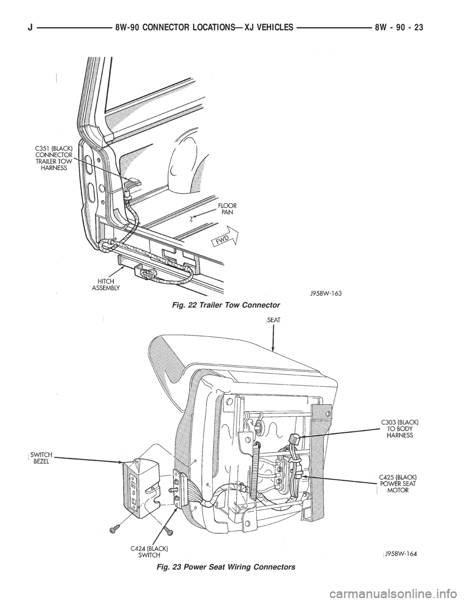
Fig. 22 Trailer Tow Connector
Fig. 23 Power Seat Wiring Connectors
J8W-90 CONNECTOR LOCATIONSÐXJ VEHICLES 8W - 90 - 23