1995 JEEP XJ roof rack
[x] Cancel search: roof rackPage 322 of 2158

(4) With the degaussing tool still energized, slowly
back it away from the screw until the tool is at least
2 feet from the screw head, then unplug the tool.
(5) Place an 8-1/2 X 11 inch piece of paper, oriented
lengthwise from front to rear, on the center line of
the roof at the windshield header (Fig. 4). The pur-
pose of the paper is to protect the roof panel from
scratches and define the area to be demagnetized.
(6) Plug in the degaussing tool, while keeping the
tool at least 2 feet away from the compass unit.
(7) Slowly approach the center line of the roof
panel at the windshield header with the degaussing
tool plugged in.
(8) Contact the roof panel with the tip of the tool.
Be sure template is in place to avoid scratching the
roof panel. Using a slow, back and forth sweeping
motion and allowing 1/2-inch between passes (Fig. 4),
move the tool at least 4 inches either side of the roof
center line and 11 inches back from the windshield
header.
(9) With the degaussing tool still energized, slowly
back it away from the roof panel until the tip is at
least 2 feet from the roof. Then unplug the tool.
(10) Calibrate the compass and adjust variance as
described in this group.OVERHEAD CONSOLE REMOVE/INSTALL
(1) Remove screw forward of the compass unit (Fig.
5).
(2) Flex housing outward while pressing upward to
disengage the housing from the rear bracket (Arrow
1 in Fig. 5).
(3) Slide console rearward until the console de-
taches from the front mounting bracket (Arrow 2 in
Fig. 5).
(4) While pressing up on rear of console (Arrow 1
in Fig. 5), slide console forward, holding front away
from headliner (Arrow 2 in Fig. 5). Move console for-
ward until the rear detaches from headliner and be-
comes free (Fig. 6).
(5) Disconnect wire harnesses from keyless entry
and compass/thermometer modules (Figs. 7 and 8).
(6) Reverse removal procedures to install. Be sure
to flex housing outward near the keyless entry re-
ceiver until the console snaps onto the rear mounting
bracket.
Fig. 4 Roof Demagnetizing Pattern
Fig. 5 Remove/Install Overhead Console
Fig. 6 Remove/Install Overhead Console
8C - 6 OVERHEAD CONSOLEJ
Page 350 of 2158
IGNITION SWITCHÐXJ MODELS
IGNITION SWITCH AND KEY CYLINDER SERVICE
The ignition switch is located on the steering col-
umn. The Key-In-Switch and Halo Light are integral
with the ignition switch. Refer to Group 8U for Key-
In-Switch and Halo Light diagnosis for XJ models.
Refer to Group 8W, Wiring for ignition switch wir-
ing circuits.
REMOVAL
(1) Disconnect negative battery cable from battery.
(2) If vehicle has a tilt column, remove tilt lever by
turning it counterclockwise.
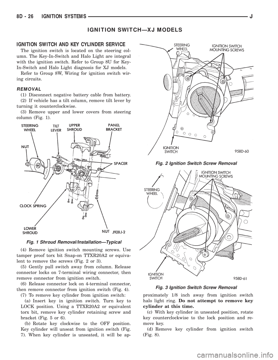
(3) Remove upper and lower covers from steering
column (Fig. 1).
(4) Remove ignition switch mounting screws. Use
tamper proof torx bit Snap-on TTXR20A2 or equiva-
lent to remove the screws (Fig. 2 or 3).
(5) Gently pull switch away from column. Release
connector locks on 7-terminal wiring connector, then
remove connector from ignition switch.
(6) Release connector lock on 4-terminal connector,
then remove connector from ignition switch (Fig. 4).
(7) To remove key cylinder from ignition switch:
(a) Insert key in ignition switch. Turn key to
LOCK position. Using a TTXR20A2 or equivalent
torx bit, remove key cylinder retaining screw and
bracket (Fig. 5 or 6).
(b) Rotate key clockwise to the OFF position.
Key cylinder will unseat from ignition switch (Fig.
7). When key cylinder is unseated, it will be ap-proximately 1/8 inch away from ignition switch
halo light ring.Do not attempt to remove key
cylinder at this time.
(c) With key cylinder in unseated position, rotate
key counterclockwise to the lock position and re-
move key.
(d) Remove key cylinder from ignition switch
(Fig. 8).
Fig. 1 Shroud Removal/InstallationÐTypical
Fig. 2 Ignition Switch Screw Removal
Fig. 3 Ignition Switch Screw Removal
8D - 26 IGNITION SYSTEMSJ
Page 431 of 2158
SERVICE PROCEDURES
WARNING: ON VEHICLES EQUIPPED WITH AN AIRBAG,
REFER TO GROUP 8M - RESTRAINT SYSTEMS BEFORE
ATTEMPTING STEERING WHEEL COMPONENT DIAGNO-
SIS OR SERVICE. FAILURE TO TAKE PROPER PRECAU-
TIONS COULD RESULT IN ACCIDENTAL AIRBAG DE-
PLOYMENT AND POSSIBLE PERSONAL INJURY.
MULTI-FUNCTION SWITCH REMOVE/INSTALL - XJ
(1) Disconnect battery negative cable.
(2) Remove tilt lever (if equipped).
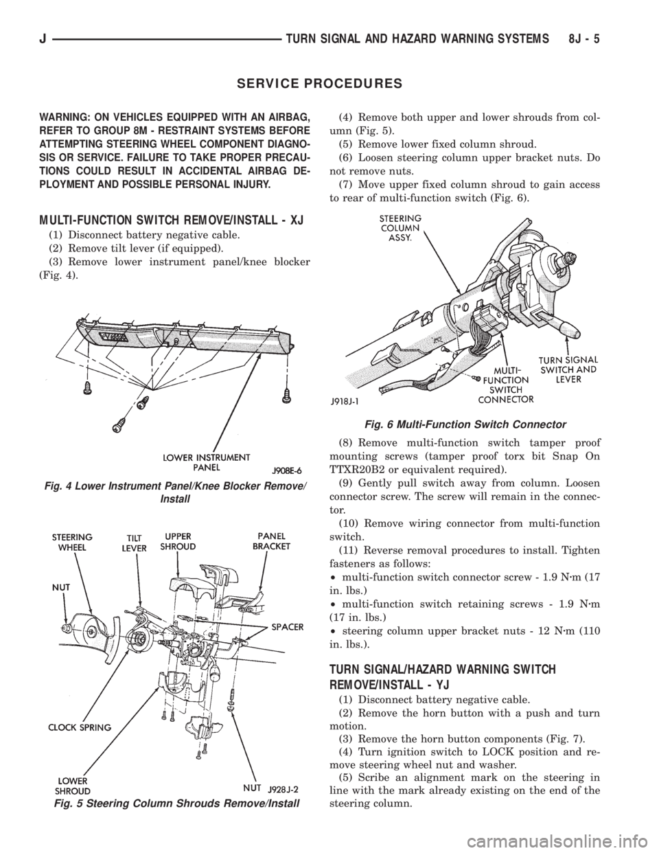
(3) Remove lower instrument panel/knee blocker
(Fig. 4).(4) Remove both upper and lower shrouds from col-
umn (Fig. 5).
(5) Remove lower fixed column shroud.
(6) Loosen steering column upper bracket nuts. Do
not remove nuts.
(7) Move upper fixed column shroud to gain access
to rear of multi-function switch (Fig. 6).
(8) Remove multi-function switch tamper proof
mounting screws (tamper proof torx bit Snap On
TTXR20B2 or equivalent required).
(9) Gently pull switch away from column. Loosen
connector screw. The screw will remain in the connec-
tor.
(10) Remove wiring connector from multi-function
switch.
(11) Reverse removal procedures to install. Tighten
fasteners as follows:
²multi-function switch connector screw - 1.9 Nzm (17
in. lbs.)
²multi-function switch retaining screws - 1.9 Nzm
(17 in. lbs.)
²steering column upper bracket nuts - 12 Nzm(110
in. lbs.).
TURN SIGNAL/HAZARD WARNING SWITCH
REMOVE/INSTALL - YJ
(1) Disconnect battery negative cable.
(2) Remove the horn button with a push and turn
motion.
(3) Remove the horn button components (Fig. 7).
(4) Turn ignition switch to LOCK position and re-
move steering wheel nut and washer.
(5) Scribe an alignment mark on the steering in
line with the mark already existing on the end of the
steering column.
Fig. 5 Steering Column Shrouds Remove/Install
Fig. 4 Lower Instrument Panel/Knee Blocker Remove/
Install
Fig. 6 Multi-Function Switch Connector
JTURN SIGNAL AND HAZARD WARNING SYSTEMS 8J - 5
Page 441 of 2158
(8) Remove the wiper motor mounting screws.
(9) Remove the wiper motor.
(10) Reverse removal procedures to install. Tighten
pivot pin retaining nut to 4 Nzm (32 in. lbs.). Lubri-
cate the bezel nipples with a small amount of water
when installing washer hoses. The liftgate wiper
blade should be installed parallel to window opening
and no closer than 5mm to window seal when oper-
ated on a wet window (Fig. 9).
WINDSHIELD WIPER/WASHER SWITCH
REMOVE/INSTALL
(1) Disconnect battery negative cable.
(2) Remove lower instrument panel/knee blocker
assembly. Refer to Group 8E - Instrument Panel and
Gauges for procedure.
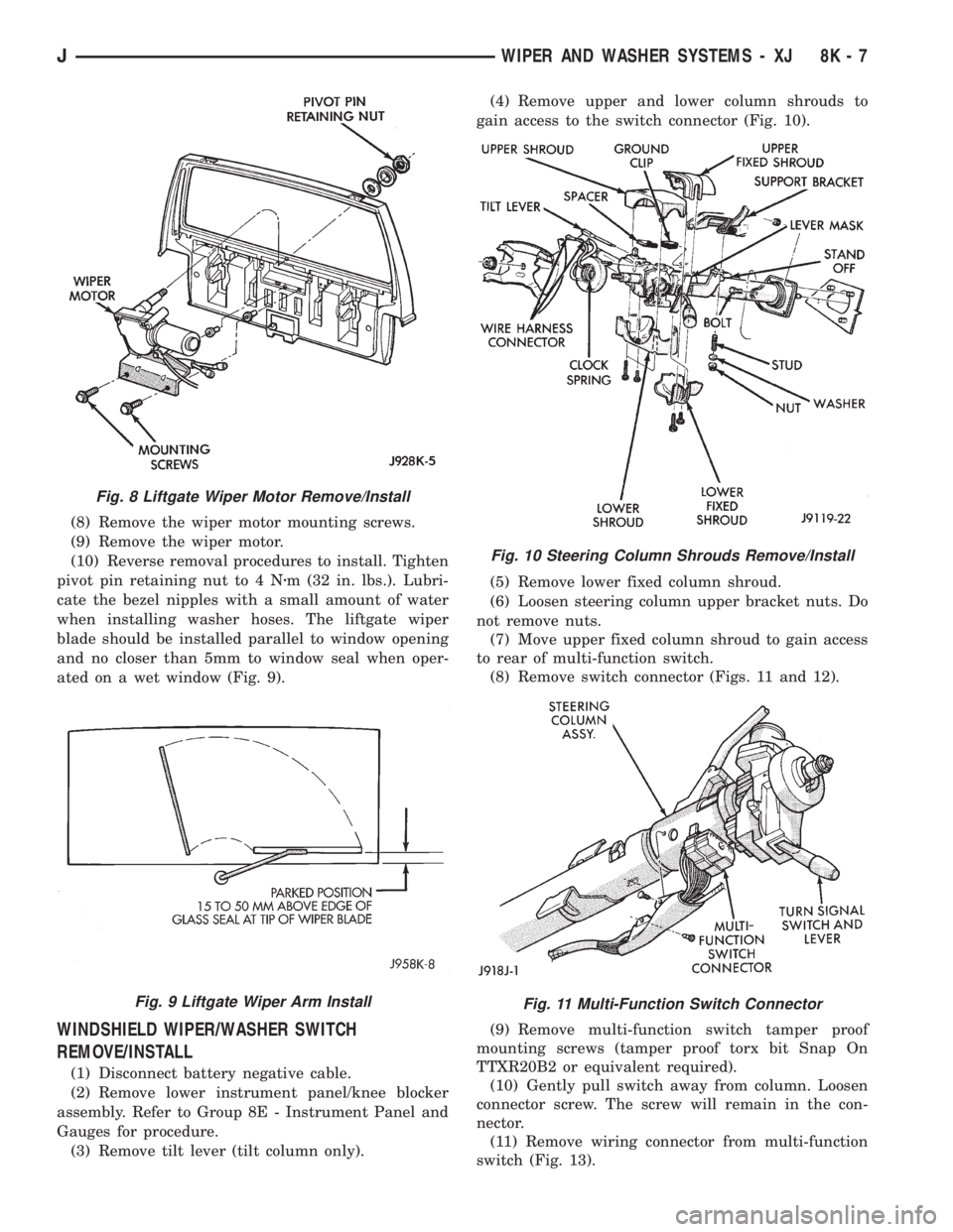
(3) Remove tilt lever (tilt column only).(4) Remove upper and lower column shrouds to
gain access to the switch connector (Fig. 10).
(5) Remove lower fixed column shroud.
(6) Loosen steering column upper bracket nuts. Do
not remove nuts.
(7) Move upper fixed column shroud to gain access
to rear of multi-function switch.
(8) Remove switch connector (Figs. 11 and 12).
(9) Remove multi-function switch tamper proof
mounting screws (tamper proof torx bit Snap On
TTXR20B2 or equivalent required).
(10) Gently pull switch away from column. Loosen
connector screw. The screw will remain in the con-
nector.
(11) Remove wiring connector from multi-function
switch (Fig. 13).
Fig. 8 Liftgate Wiper Motor Remove/Install
Fig. 9 Liftgate Wiper Arm Install
Fig. 10 Steering Column Shrouds Remove/Install
Fig. 11 Multi-Function Switch Connector
JWIPER AND WASHER SYSTEMS - XJ 8K - 7
Page 471 of 2158
INSTALLATION
(1) Squeeze the tabs on the side of the fog lamp
switch and insert the switch in the instrument panel
cavity.
(2) Connect the wire harness connector to the
switch.
(3) Install the fog lamp switch cover.
(4) Position the bezel on the instrument panel and
install the attaching screws. Tighten the screws se-
curely.
MULTI-FUNCTION SWITCH SERVICE
PROCEDURESÐXJ
REMOVAL
(1) Disconnect battery negative cable.
(2) Remove lower instrument panel screws along
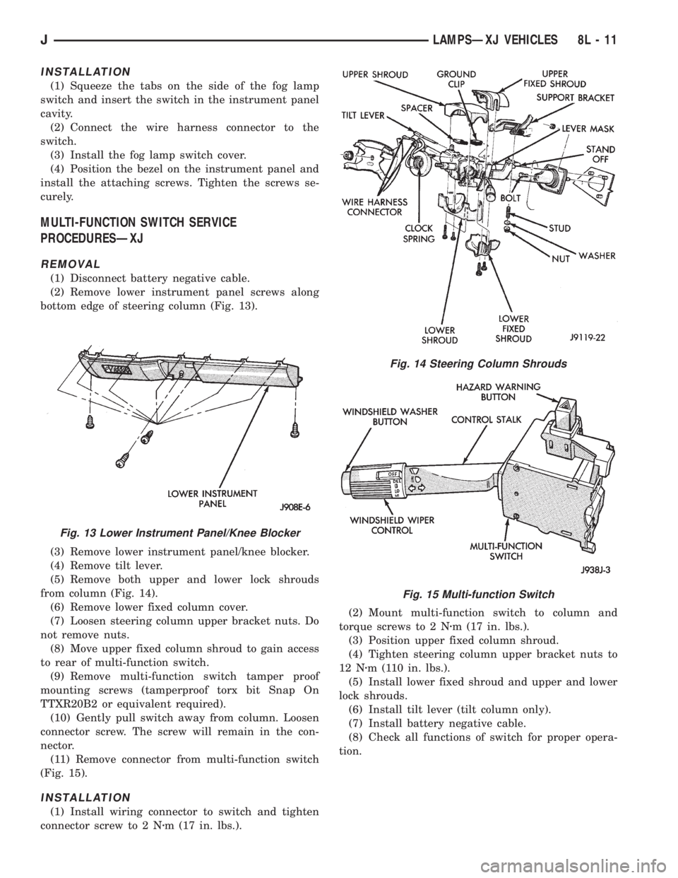
bottom edge of steering column (Fig. 13).
(3) Remove lower instrument panel/knee blocker.
(4) Remove tilt lever.
(5) Remove both upper and lower lock shrouds
from column (Fig. 14).
(6) Remove lower fixed column cover.
(7) Loosen steering column upper bracket nuts. Do
not remove nuts.
(8) Move upper fixed column shroud to gain access
to rear of multi-function switch.
(9) Remove multi-function switch tamper proof
mounting screws (tamperproof torx bit Snap On
TTXR20B2 or equivalent required).
(10) Gently pull switch away from column. Loosen
connector screw. The screw will remain in the con-
nector.
(11) Remove connector from multi-function switch
(Fig. 15).
INSTALLATION
(1) Install wiring connector to switch and tighten
connector screw to 2 Nzm (17 in. lbs.).(2) Mount multi-function switch to column and
torque screws to 2 Nzm (17 in. lbs.).
(3) Position upper fixed column shroud.
(4) Tighten steering column upper bracket nuts to
12 Nzm (110 in. lbs.).
(5) Install lower fixed shroud and upper and lower
lock shrouds.
(6) Install tilt lever (tilt column only).
(7) Install battery negative cable.
(8) Check all functions of switch for proper opera-
tion.
Fig. 13 Lower Instrument Panel/Knee Blocker
Fig. 14 Steering Column Shrouds
Fig. 15 Multi-function Switch
JLAMPSÐXJ VEHICLES 8L - 11
Page 1946 of 2158
(3) For power/manual mirrors, remove the inside
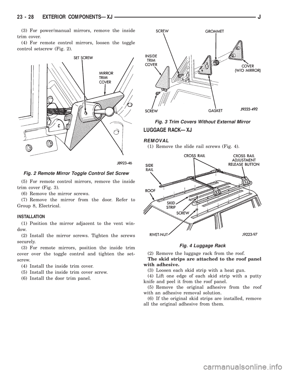
trim cover.
(4) For remote control mirrors, loosen the toggle
control setscrew (Fig. 2).
(5) For remote control mirrors, remove the inside
trim cover (Fig. 3).
(6) Remove the mirror screws.
(7) Remove the mirror from the door. Refer to
Group 8, Electrical.
INSTALLATION
(1) Position the mirror adjacent to the vent win-
dow.
(2) Install the mirror screws. Tighten the screws
securely.
(3) For remote mirrors, position the inside trim
cover over the toggle control and tighten the set-
screw.
(4) Install the inside trim cover.
(5) Install the inside trim cover screw.
(6) Install the door trim panel.
LUGGAGE RACKÐXJ
REMOVAL
(1) Remove the slide rail screws (Fig. 4).
(2) Remove the luggage rack from the roof.
The skid strips are attached to the roof panel
with adhesive.
(3) Loosen each skid strip with a heat gun.
(4) Lift one edge of each skid strip with a putty
knife and peel it from the roof panel.
(5) Remove the original adhesive from the roof
with an adhesive removal solution.
(6) If the original skid strips are installed, remove
all the original adhesive from them.
Fig. 2 Remote Mirror Toggle Control Set Screw
Fig. 3 Trim Covers Without External Mirror
Fig. 4 Luggage Rack
23 - 28 EXTERIOR COMPONENTSÐXJJ
Page 1947 of 2158
INSTALLATION
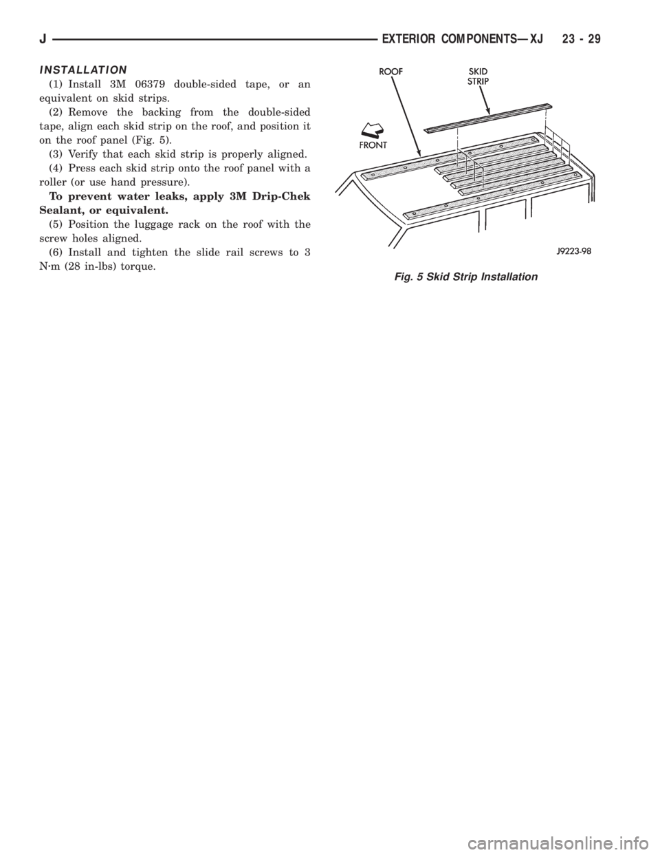
(1) Install 3M 06379 double-sided tape, or an
equivalent on skid strips.
(2) Remove the backing from the double-sided
tape, align each skid strip on the roof, and position it
on the roof panel (Fig. 5).
(3) Verify that each skid strip is properly aligned.
(4) Press each skid strip onto the roof panel with a
roller (or use hand pressure).
To prevent water leaks, apply 3M Drip-Chek
Sealant, or equivalent.
(5) Position the luggage rack on the roof with the
screw holes aligned.
(6) Install and tighten the slide rail screws to 3
Nzm (28 in-lbs) torque.
Fig. 5 Skid Strip Installation
JEXTERIOR COMPONENTSÐXJ 23 - 29
Page 1985 of 2158
INSTALLATION
(1) Apply adhesive to the act surface on the sup-
port bracket according as follows:
²crush the vial in the plastic housing of the accel-
erator to saturate the felt applicator.
²remove the paper sleeve.
²apply a generous amount of accelerator to the con-
tact surface on the mirror support bracket.
²do not touch the support bracket contact surface
after the accelerator has been applied.
²
allow the accelerator to dry for at least five minutes.
and
(2) Apply accelerator to the support bracket con-
tact surface on the windshield glass. Allow the accel-
erator to dry for one minute.
(3) Install the mirror bracket on the windshield
glass as follows:
²apply one drop of adhesive at the center of support
bracket contact surface on windshield glass.
²immediately apply an even coat of adhesive to the
contact surface on the support bracket.
²align the support bracket with the position refer-
ence lines on the windshield glass, then
²press and hold the support bracket in-place for at
least one minute.
Ensure that the mirror support bracket is
correctly aligned because the adhesive will
cure rapidly.
(4) Allow the adhesive to cure for 8-10 minutes,
then remove any residue adhesive with an alcohol-
dampened cloth.
(5) Allow the adhesive to cure for an additional
8-10 minutes before installing the mirror base on the
support bracket.
DESCRIPTION AND OPERATION
SAFETY PRECAUTIONS
WARNING: DO NOT OPERATE THE VEHICLE
WITHIN 24 HOURS OF WINDSHIELD INSTALLATION.
IT TAKES AT LEAST 24 HOURS FOR THE URE-
THANE ADHESIVE TO CURE. IF IT IS NOT CURED,
THE WINDSHIELD MAY NOT PERFORM PROPERLY
IN AN ACCIDENT.
URETHANE ADHESIVES ARE APPLIED AS A SYS-
TEM. USE GLASS CLEANER, GLASS PREP SOL-
VENT, GLASS PRIMER, AND PINCHWELD (FENCE)
PRIMER PROVIDED BY THE ADHESIVE MANUFAC-
TURER. IF NOT, STRUCTURAL INTEGRITY COULD
BE COMPROMISED.
BE SURE TO REFER TO THE URETHANE MANU-
FACTURER'S DIRECTIONS FOR CURING TIME
SPECIFICATIONS, AND DO NOT USE ADHESIVE AF-
TER ITS EXPIRATION DATE.
VAPORS THAT ARE EMITTED FROM THE URE-
THANE ADHESIVE OR PRIMER COULD CAUSE
PERSONAL INJURY, USE THEM IN A WELL VENTI-
LATED AREA.
SKIN CONTACT WITH URETHANE ADHESIVE
SHOULD BE AVOIDED, OR PERSONAL INJURY MAY
RESULT.
ALWAYS WEAR EYE AND HAND PROTECTION
WHEN WORKING WITH GLASS.
CAUTION: Protect all painted or trimmed surfaces
from coming in contact with urethane or primers.
Be careful not to damage painted surfaces when
removing moldings or cutting urethane around
windshield.
It is difficult to salvage a windshield during the re-
moval operation. The windshield is part of the struc-
tural support for the roof. The urethane bonding
used to secure the windshield to the fence is difficult
to cut or clean from any surface. If the moldings are
set in urethane, it would also be unlikely they could
be salvaged. Before removing the windshield, check
the availability of the windshield and moldings from
the parts supplier.
JSTATIONARY WINDOW GLASSÐXJ 23 - 671995 Jeep Cherokee/Wrangler
Publication No. 81-370-5146
TSB 26-05-95 July, 1995