1995 JEEP CHEROKEE transmission
[x] Cancel search: transmissionPage 257 of 2198
(10) Check and adjust automatic transmission
fluid level (if equipped).
COOLING SYSTEM HOSES
Rubber hoses route coolant to and from the radia-
tor, intake manifold and heater core. All XJ models
equipped with air conditioning have a coolant control
valve. This is located in-line with the heater core in-
let and outlet hoses. It controls coolant flow to the
heater core when the air conditioning system is in
operation.
Radiator lower hoses are spring-reinforced to pre-
vent collapse from water pump suction at moderate
and high engine speeds.
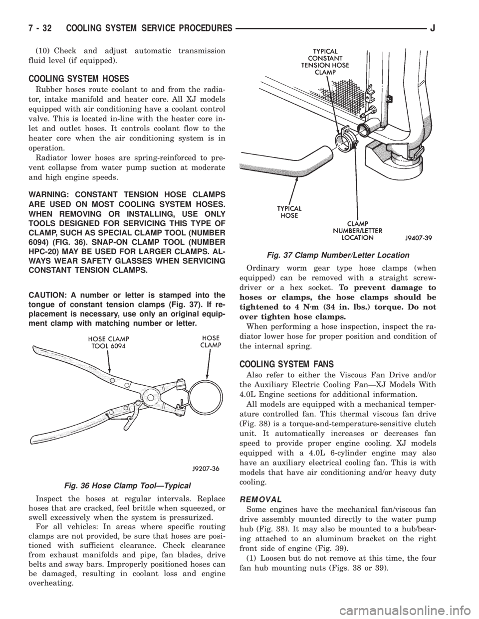
WARNING: CONSTANT TENSION HOSE CLAMPS
ARE USED ON MOST COOLING SYSTEM HOSES.
WHEN REMOVING OR INSTALLING, USE ONLY
TOOLS DESIGNED FOR SERVICING THIS TYPE OF
CLAMP, SUCH AS SPECIAL CLAMP TOOL (NUMBER
6094) (FIG. 36). SNAP-ON CLAMP TOOL (NUMBER
HPC-20) MAY BE USED FOR LARGER CLAMPS. AL-
WAYS WEAR SAFETY GLASSES WHEN SERVICING
CONSTANT TENSION CLAMPS.
CAUTION: A number or letter is stamped into the
tongue of constant tension clamps (Fig. 37). If re-
placement is necessary, use only an original equip-
ment clamp with matching number or letter.
Inspect the hoses at regular intervals. Replace
hoses that are cracked, feel brittle when squeezed, or
swell excessively when the system is pressurized.
For all vehicles: In areas where specific routing
clamps are not provided, be sure that hoses are posi-
tioned with sufficient clearance. Check clearance
from exhaust manifolds and pipe, fan blades, drive
belts and sway bars. Improperly positioned hoses can
be damaged, resulting in coolant loss and engine
overheating.Ordinary worm gear type hose clamps (when
equipped) can be removed with a straight screw-
driver or a hex socket.To prevent damage to
hoses or clamps, the hose clamps should be
tightened to 4 Nzm (34 in. lbs.) torque. Do not
over tighten hose clamps.
When performing a hose inspection, inspect the ra-
diator lower hose for proper position and condition of
the internal spring.
COOLING SYSTEM FANS
Also refer to either the Viscous Fan Drive and/or
the Auxiliary Electric Cooling FanÐXJ Models With
4.0L Engine sections for additional information.
All models are equipped with a mechanical temper-
ature controlled fan. This thermal viscous fan drive
(Fig. 38) is a torque-and-temperature-sensitive clutch
unit. It automatically increases or decreases fan
speed to provide proper engine cooling. XJ models
equipped with a 4.0L 6-cylinder engine may also
have an auxiliary electrical cooling fan. This is with
models that have air conditioning and/or heavy duty
cooling.
REMOVAL
Some engines have the mechanical fan/viscous fan
drive assembly mounted directly to the water pump
hub (Fig. 38). It may also be mounted to a hub/bear-
ing attached to an aluminum bracket on the right
front side of engine (Fig. 39).
(1) Loosen but do not remove at this time, the four
fan hub mounting nuts (Figs. 38 or 39).
Fig. 36 Hose Clamp ToolÐTypical
Fig. 37 Clamp Number/Letter Location
7 - 32 COOLING SYSTEM SERVICE PROCEDURESJ
Page 261 of 2198
nostic Procedures manual for diagnostic information
and operation of the DRB scan tool.
To test operation of the fan relay only, refer to Re-
laysÐOperation/Testing. This can be found in Group
14, Fuel Systems.
REMOVAL
The auxiliary cooling fan is attached to the radia-
tor upper crossmember behind the radiator.
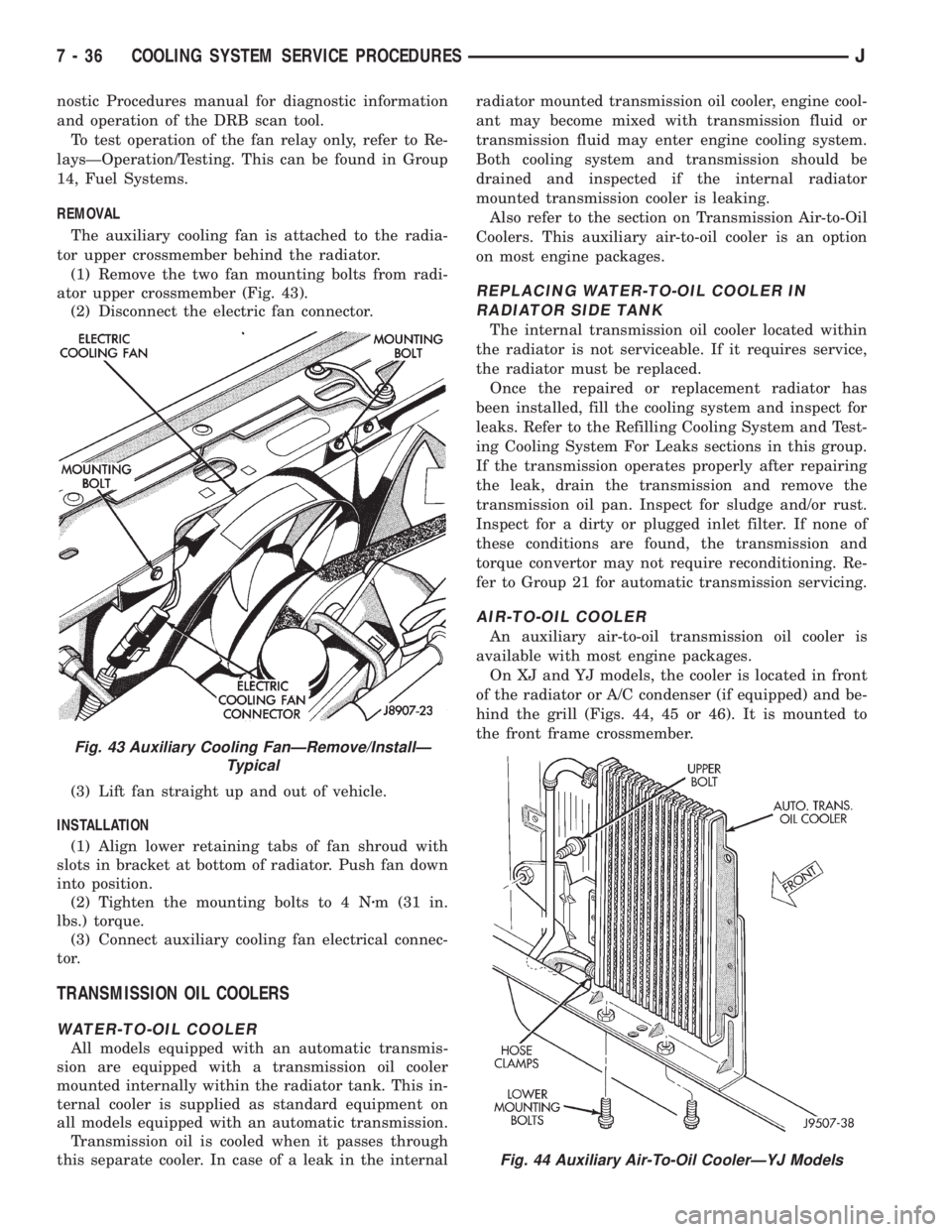
(1) Remove the two fan mounting bolts from radi-
ator upper crossmember (Fig. 43).
(2) Disconnect the electric fan connector.
(3) Lift fan straight up and out of vehicle.
INSTALLATION
(1) Align lower retaining tabs of fan shroud with
slots in bracket at bottom of radiator. Push fan down
into position.
(2) Tighten the mounting bolts to 4 Nzm (31 in.
lbs.) torque.
(3) Connect auxiliary cooling fan electrical connec-
tor.
TRANSMISSION OIL COOLERS
WATER-TO-OIL COOLER
All models equipped with an automatic transmis-
sion are equipped with a transmission oil cooler
mounted internally within the radiator tank. This in-
ternal cooler is supplied as standard equipment on
all models equipped with an automatic transmission.
Transmission oil is cooled when it passes through
this separate cooler. In case of a leak in the internalradiator mounted transmission oil cooler, engine cool-
ant may become mixed with transmission fluid or
transmission fluid may enter engine cooling system.
Both cooling system and transmission should be
drained and inspected if the internal radiator
mounted transmission cooler is leaking.
Also refer to the section on Transmission Air-to-Oil
Coolers. This auxiliary air-to-oil cooler is an option
on most engine packages.
REPLACING WATER-TO-OIL COOLER IN
RADIATOR SIDE TANK
The internal transmission oil cooler located within
the radiator is not serviceable. If it requires service,
the radiator must be replaced.
Once the repaired or replacement radiator has
been installed, fill the cooling system and inspect for
leaks. Refer to the Refilling Cooling System and Test-
ing Cooling System For Leaks sections in this group.
If the transmission operates properly after repairing
the leak, drain the transmission and remove the
transmission oil pan. Inspect for sludge and/or rust.
Inspect for a dirty or plugged inlet filter. If none of
these conditions are found, the transmission and
torque convertor may not require reconditioning. Re-
fer to Group 21 for automatic transmission servicing.
AIR-TO-OIL COOLER
An auxiliary air-to-oil transmission oil cooler is
available with most engine packages.
On XJ and YJ models, the cooler is located in front
of the radiator or A/C condenser (if equipped) and be-
hind the grill (Figs. 44, 45 or 46). It is mounted to
the front frame crossmember.
Fig. 43 Auxiliary Cooling FanÐRemove/InstallÐ
Typical
Fig. 44 Auxiliary Air-To-Oil CoolerÐYJ Models
7 - 36 COOLING SYSTEM SERVICE PROCEDURESJ
Page 262 of 2198
The auxiliary oil coolers on all models operate in
conjunction with the internal radiator mounted main
oil cooler. The transmission oil is routed through the
main cooler first, then the auxiliary cooler, before re-
turning to the transmission.REMOVAL/INSTALLATIONÐXJ MODELS
(1) Remove the grill mounting screws and remove
the grill. Refer to Group 23, Body for procedures.
(2) Place a drain pan below the transmission oil
cooler.
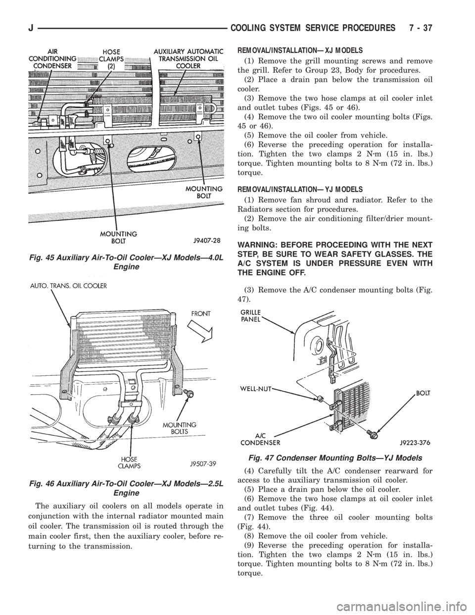
(3) Remove the two hose clamps at oil cooler inlet
and outlet tubes (Figs. 45 or 46).
(4) Remove the two oil cooler mounting bolts (Figs.
45 or 46).
(5) Remove the oil cooler from vehicle.
(6) Reverse the preceding operation for installa-
tion. Tighten the two clamps 2 Nzm (15 in. lbs.)
torque. Tighten mounting bolts to 8 Nzm (72 in. lbs.)
torque.
REMOVAL/INSTALLATIONÐYJ MODELS
(1) Remove fan shroud and radiator. Refer to the
Radiators section for procedures.
(2) Remove the air conditioning filter/drier mount-
ing bolts.
WARNING: BEFORE PROCEEDING WITH THE NEXT
STEP, BE SURE TO WEAR SAFETY GLASSES. THE
A/C SYSTEM IS UNDER PRESSURE EVEN WITH
THE ENGINE OFF.
(3) Remove the A/C condenser mounting bolts (Fig.
47).
(4) Carefully tilt the A/C condenser rearward for
access to the auxiliary transmission oil cooler.
(5) Place a drain pan below the oil cooler.
(6) Remove the two hose clamps at oil cooler inlet
and outlet tubes (Fig. 44).
(7) Remove the three oil cooler mounting bolts
(Fig. 44).
(8) Remove the oil cooler from vehicle.
(9) Reverse the preceding operation for installa-
tion. Tighten the two clamps 2 Nzm (15 in. lbs.)
torque. Tighten mounting bolts to 8 Nzm (72 in. lbs.)
torque.
Fig. 45 Auxiliary Air-To-Oil CoolerÐXJ ModelsÐ4.0L
Engine
Fig. 46 Auxiliary Air-To-Oil CoolerÐXJ ModelsÐ2.5L
Engine
Fig. 47 Condenser Mounting BoltsÐYJ Models
JCOOLING SYSTEM SERVICE PROCEDURES 7 - 37
Page 282 of 2198
STARTING SYSTEM
GENERAL INFORMATION
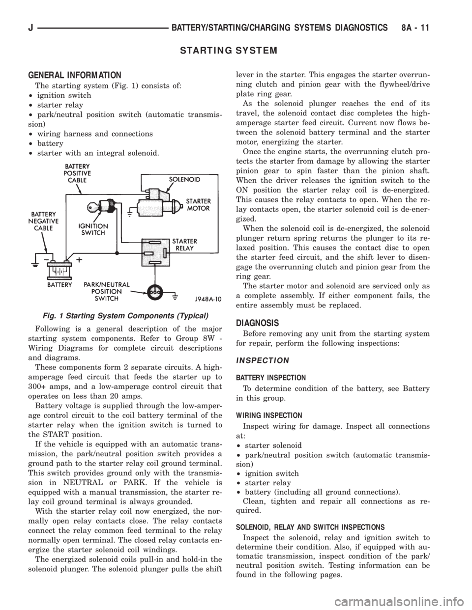
The starting system (Fig. 1) consists of:
²ignition switch
²starter relay
²park/neutral position switch (automatic transmis-
sion)
²wiring harness and connections
²battery
²starter with an integral solenoid.
Following is a general description of the major
starting system components. Refer to Group 8W -
Wiring Diagrams for complete circuit descriptions
and diagrams.
These components form 2 separate circuits. A high-
amperage feed circuit that feeds the starter up to
300+ amps, and a low-amperage control circuit that
operates on less than 20 amps.
Battery voltage is supplied through the low-amper-
age control circuit to the coil battery terminal of the
starter relay when the ignition switch is turned to
the START position.
If the vehicle is equipped with an automatic trans-
mission, the park/neutral position switch provides a
ground path to the starter relay coil ground terminal.
This switch provides ground only with the transmis-
sion in NEUTRAL or PARK. If the vehicle is
equipped with a manual transmission, the starter re-
lay coil ground terminal is always grounded.
With the starter relay coil now energized, the nor-
mally open relay contacts close. The relay contacts
connect the relay common feed terminal to the relay
normally open terminal. The closed relay contacts en-
ergize the starter solenoid coil windings.
The energized solenoid coils pull-in and hold-in the
solenoid plunger. The solenoid plunger pulls the shiftlever in the starter. This engages the starter overrun-
ning clutch and pinion gear with the flywheel/drive
plate ring gear.
As the solenoid plunger reaches the end of its
travel, the solenoid contact disc completes the high-
amperage starter feed circuit. Current now flows be-
tween the solenoid battery terminal and the starter
motor, energizing the starter.
Once the engine starts, the overrunning clutch pro-
tects the starter from damage by allowing the starter
pinion gear to spin faster than the pinion shaft.
When the driver releases the ignition switch to the
ON position the starter relay coil is de-energized.
This causes the relay contacts to open. When the re-
lay contacts open, the starter solenoid coil is de-ener-
gized.
When the solenoid coil is de-energized, the solenoid
plunger return spring returns the plunger to its re-
laxed position. This causes the contact disc to open
the starter feed circuit, and the shift lever to disen-
gage the overrunning clutch and pinion gear from the
ring gear.
The starter motor and solenoid are serviced only as
a complete assembly. If either component fails, the
entire assembly must be replaced.
DIAGNOSIS
Before removing any unit from the starting system
for repair, perform the following inspections:
INSPECTION
BATTERY INSPECTION
To determine condition of the battery, see Battery
in this group.
WIRING INSPECTION
Inspect wiring for damage. Inspect all connections
at:
²starter solenoid
²park/neutral position switch (automatic transmis-
sion)
²ignition switch
²starter relay
²battery (including all ground connections).
Clean, tighten and repair all connections as re-
quired.
SOLENOID, RELAY AND SWITCH INSPECTIONS
Inspect the solenoid, relay and ignition switch to
determine their condition. Also, if equipped with au-
tomatic transmission, inspect condition of the park/
neutral position switch. Testing information can be
found in the following pages.
Fig. 1 Starting System Components (Typical)
JBATTERY/STARTING/CHARGING SYSTEMS DIAGNOSTICS 8A - 11
Page 284 of 2198
COLD CRANKING TEST
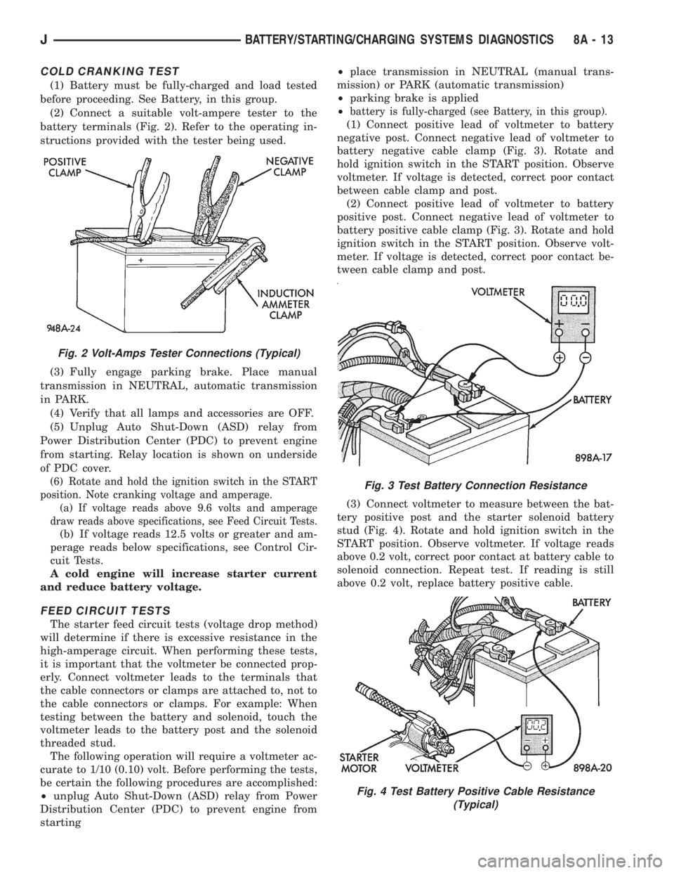
(1) Battery must be fully-charged and load tested
before proceeding. See Battery, in this group.
(2) Connect a suitable volt-ampere tester to the
battery terminals (Fig. 2). Refer to the operating in-
structions provided with the tester being used.
(3) Fully engage parking brake. Place manual
transmission in NEUTRAL, automatic transmission
in PARK.
(4) Verify that all lamps and accessories are OFF.
(5) Unplug Auto Shut-Down (ASD) relay from
Power Distribution Center (PDC) to prevent engine
from starting. Relay location is shown on underside
of PDC cover.
(6) Rotate and hold the ignition switch in the START
position. Note cranking voltage and amperage.
(a) If voltage reads above 9.6 volts and amperage
draw reads above specifications, see Feed Circuit Tests.
(b) If voltage reads 12.5 volts or greater and am-
perage reads below specifications, see Control Cir-
cuit Tests.
A cold engine will increase starter current
and reduce battery voltage.
FEED CIRCUIT TESTS
The starter feed circuit tests (voltage drop method)
will determine if there is excessive resistance in the
high-amperage circuit. When performing these tests,
it is important that the voltmeter be connected prop-
erly. Connect voltmeter leads to the terminals that
the cable connectors or clamps are attached to, not to
the cable connectors or clamps. For example: When
testing between the battery and solenoid, touch the
voltmeter leads to the battery post and the solenoid
threaded stud.
The following operation will require a voltmeter ac-
curate to 1/10 (0.10) volt. Before performing the tests,
be certain the following procedures are accomplished:
²unplug Auto Shut-Down (ASD) relay from Power
Distribution Center (PDC) to prevent engine from
starting²place transmission in NEUTRAL (manual trans-
mission) or PARK (automatic transmission)
²parking brake is applied
²
battery is fully-charged (see Battery, in this group).
(1) Connect positive lead of voltmeter to battery
negative post. Connect negative lead of voltmeter to
battery negative cable clamp (Fig. 3). Rotate and
hold ignition switch in the START position. Observe
voltmeter. If voltage is detected, correct poor contact
between cable clamp and post.
(2) Connect positive lead of voltmeter to battery
positive post. Connect negative lead of voltmeter to
battery positive cable clamp (Fig. 3). Rotate and hold
ignition switch in the START position. Observe volt-
meter. If voltage is detected, correct poor contact be-
tween cable clamp and post.
(3) Connect voltmeter to measure between the bat-
tery positive post and the starter solenoid battery
stud (Fig. 4). Rotate and hold ignition switch in the
START position. Observe voltmeter. If voltage reads
above 0.2 volt, correct poor contact at battery cable to
solenoid connection. Repeat test. If reading is still
above 0.2 volt, replace battery positive cable.
Fig. 2 Volt-Amps Tester Connections (Typical)
Fig. 3 Test Battery Connection Resistance
Fig. 4 Test Battery Positive Cable Resistance
(Typical)
JBATTERY/STARTING/CHARGING SYSTEMS DIAGNOSTICS 8A - 13
Page 286 of 2198
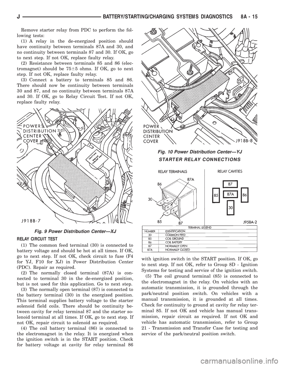
Remove starter relay from PDC to perform the fol-
lowing tests:
(1) A relay in the de-energized position should
have continuity between terminals 87A and 30, and
no continuity between terminals 87 and 30. If OK, go
to next step. If not OK, replace faulty relay.
(2) Resistance between terminals 85 and 86 (elec-
tromagnet) should be 7565 ohms. If OK, go to next
step. If not OK, replace faulty relay.
(3) Connect a battery to terminals 85 and 86.
There should now be continuity between terminals
30 and 87, and no continuity between terminals 87A
and 30. If OK, go to Relay Circuit Test. If not OK,
replace faulty relay.
RELAY CIRCUIT TEST
(1) The common feed terminal (30) is connected to
battery voltage and should be hot at all times. If OK,
go to next step. If not OK, check circuit to fuse (F4
for YJ, F10 for XJ) in Power Distribution Center
(PDC). Repair as required.
(2) The normally closed terminal (87A) is con-
nected to terminal 30 in the de-energized position,
but is not used for this application. Go to next step.
(3) The normally open terminal (87) is connected to
the battery terminal (30) in the energized position.
This terminal supplies battery voltage to the starter
solenoid field coils. There should be continuity be-
tween cavity for relay terminal 87 and the starter so-
lenoid terminal at all times. If OK, go to next step. If
not OK, repair circuit to solenoid as required.
(4) The coil battery terminal (86) is connected to
the electromagnet in the relay. It is energized when
the ignition switch is in the START position. Check
for battery voltage at cavity for relay terminal 86with ignition switch in the START position. If OK, go
to next step. If not OK, refer to Group 8D - Ignition
Systems for testing and service of the ignition switch.
(5) The coil ground terminal (85) is connected to
the electromagnet in the relay. On vehicles with an
automatic transmission, it is grounded through the
park/neutral position switch. On vehicles with a
manual transmission, it is grounded at all times.
Check for continuity to ground at cavity for relay ter-
minal 85. If not OK and vehicle has manual trans-
mission, repair circuit as required. If not OK and
vehicle has automatic transmission, refer to Group
21 - Transmission and Transfer Case for testing and
service of the park/neutral position switch.
Fig. 9 Power Distribution CenterÐXJ
Fig. 10 Power Distribution CenterÐYJ
STARTER RELAY CONNECTIONS
JBATTERY/STARTING/CHARGING SYSTEMS DIAGNOSTICS 8A - 15
Page 287 of 2198
IGNITION SWITCH TEST
Refer to Group 8D - Ignition Systems for testing
and service of this component.
PARK/NEUTRAL POSITION SWITCH TEST
Refer to Group 21 - Transmission and Transfer
Case for testing and service of this component.
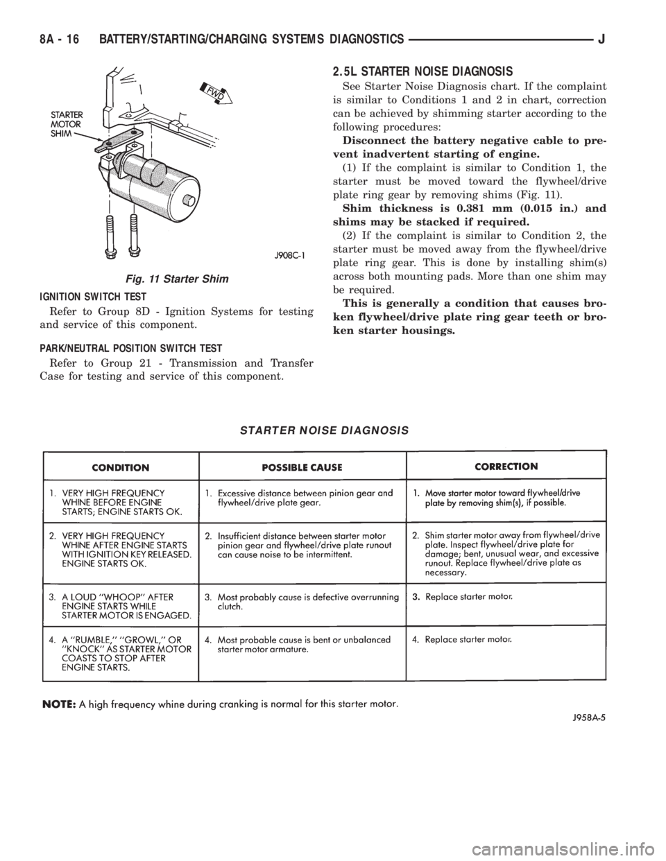
2.5L STARTER NOISE DIAGNOSIS
See Starter Noise Diagnosis chart. If the complaint
is similar to Conditions 1 and 2 in chart, correction
can be achieved by shimming starter according to the
following procedures:
Disconnect the battery negative cable to pre-
vent inadvertent starting of engine.
(1) If the complaint is similar to Condition 1, the
starter must be moved toward the flywheel/drive
plate ring gear by removing shims (Fig. 11).
Shim thickness is 0.381 mm (0.015 in.) and
shims may be stacked if required.
(2) If the complaint is similar to Condition 2, the
starter must be moved away from the flywheel/drive
plate ring gear. This is done by installing shim(s)
across both mounting pads. More than one shim may
be required.
This is generally a condition that causes bro-
ken flywheel/drive plate ring gear teeth or bro-
ken starter housings.
STARTER NOISE DIAGNOSIS
Fig. 11 Starter Shim
8A - 16 BATTERY/STARTING/CHARGING SYSTEMS DIAGNOSTICSJ
Page 299 of 2198
CAUTION: Be certain that battery cables are con-
nected to the correct battery terminals. Reverse po-
larity can damage electrical components.
(12) Place oiled felt washer on battery positive ter-
minal post.
(13) Install and tighten battery positive cable ter-
minal clamp. Then install and tighten negative cableterminal clamp. Both cable clamp bolts require
torque of 8.5 Nzm (75 in. lbs.).
(14) Apply a thin coating of petroleum jelly or
chassis grease to cable terminals and battery posts.
STARTER AND STARTER RELAY
GENERAL INFORMATION
This section covers starter and starter relay service
procedures only. For diagnostic procedures, refer to
Group 8A - Battery/Starting/Charging Systems Diag-
nostics. Service procedures for other starting system
components can be found as follows:
²battery - see Battery, in this group
²ignition switch - refer to Group 8D - Ignition Sys-
tems
²park/neutral position switch (automatic transmis-
sion) - refer to Group 21 - Transmission and Transfer
Case
²wiring harness and connectors - refer to Group 8W
- Wiring Diagrams.
STARTER
The starter motor incorporates several features to
create a reliable, efficient, compact and lightweight
unit. A planetary gear system (intermediate trans-
mission) is used between the electric motor and pin-
ion gear. This feature makes it possible to reduce the
dimensions of the starter. At the same time, it allows
higher armature rotational speed and delivers in-
creased torque through the pinion gear to the fly-
wheel or drive plate ring gear.
The use of a permanent magnet field also reduces
starter size and weight. This field consists of six
high-strength permanent magnets. The magnets are
aligned according to their polarity and are perma-
nently fixed in the starter field frame.
The starter motors for all engines are activated by
a solenoid mounted to the overrunning clutch hous-
ing. However, the starter motor/solenoid are serviced
only as a complete assembly. If either component
fails, the entire assembly must be replaced.
This unit is highly sensitive to hammering, shocks
and external pressure.
CAUTION: The starter motor MUST NOT BE
CLAMPED in a vise by the starter field frame. Doing
so may damage the magnets. It may be clamped by
the mounting flange ONLY.CAUTION: Do not connect starter motor incorrectly
when tests are being performed. The permanent
magnets may be damaged and rendered unservice-
able.
STARTER RELAY
The starter relay is an International Standards Or-
ganization (ISO) type relay, and is located in the
Power Distribution Center (PDC). Refer to underside
of PDC cover for relay location.
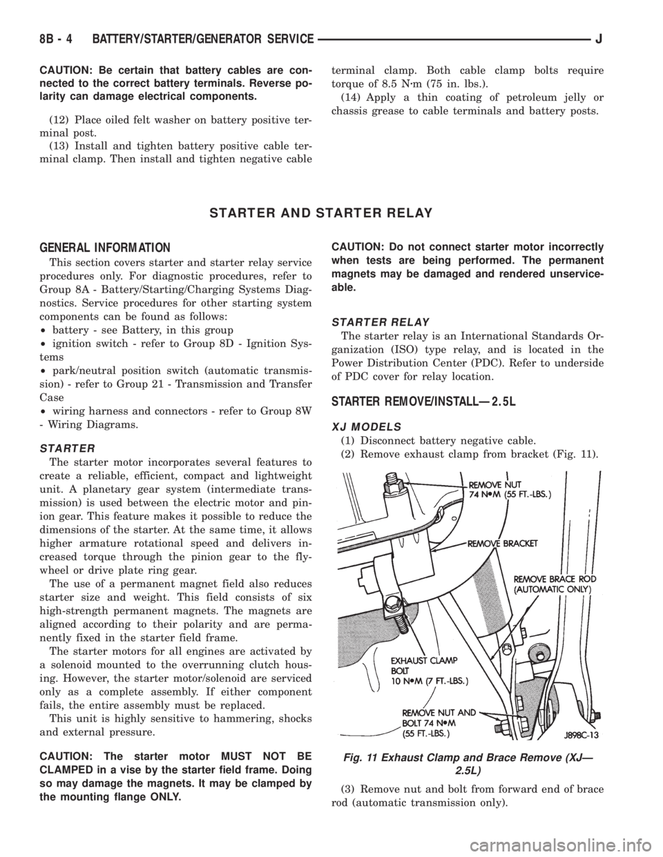
STARTER REMOVE/INSTALLÐ2.5L
XJ MODELS
(1) Disconnect battery negative cable.
(2) Remove exhaust clamp from bracket (Fig. 11).
(3) Remove nut and bolt from forward end of brace
rod (automatic transmission only).
Fig. 11 Exhaust Clamp and Brace Remove (XJÐ
2.5L)
8B - 4 BATTERY/STARTER/GENERATOR SERVICEJ