1995 JEEP CHEROKEE transmission
[x] Cancel search: transmissionPage 2078 of 2198
INTERIOR LIGHTING
INDEX
page page
Accessory Lamp and Heater Control Panel Lamp . . 1
Combination Buzzer........................ 1
Courtesy Lamps and Dome Lamps............. 1
Diagram Index............................ 2General Information........................ 1
Transmission Range Lamp................... 1
Underhood Lamp.......................... 1
GENERAL INFORMATION
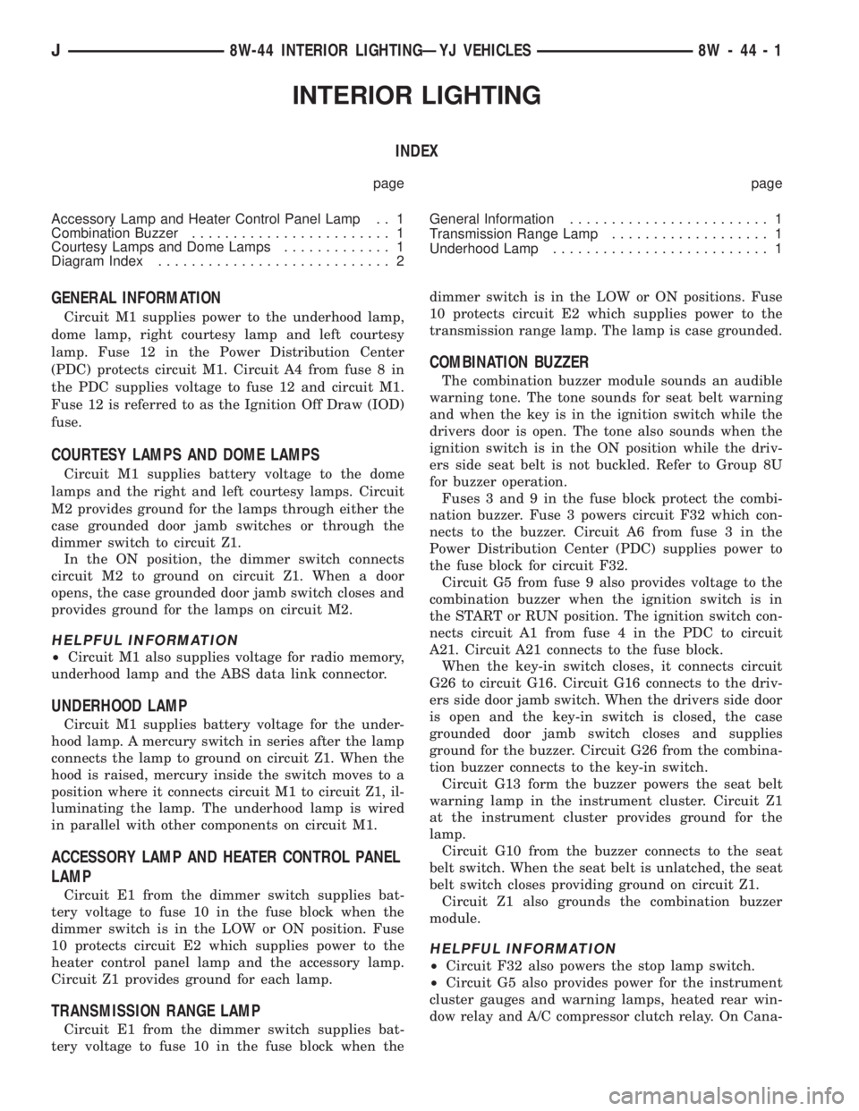
Circuit M1 supplies power to the underhood lamp,
dome lamp, right courtesy lamp and left courtesy
lamp. Fuse 12 in the Power Distribution Center
(PDC) protects circuit M1. Circuit A4 from fuse 8 in
the PDC supplies voltage to fuse 12 and circuit M1.
Fuse 12 is referred to as the Ignition Off Draw (IOD)
fuse.
COURTESY LAMPS AND DOME LAMPS
Circuit M1 supplies battery voltage to the dome
lamps and the right and left courtesy lamps. Circuit
M2 provides ground for the lamps through either the
case grounded door jamb switches or through the
dimmer switch to circuit Z1.
In the ON position, the dimmer switch connects
circuit M2 to ground on circuit Z1. When a door
opens, the case grounded door jamb switch closes and
provides ground for the lamps on circuit M2.
HELPFUL INFORMATION
²Circuit M1 also supplies voltage for radio memory,
underhood lamp and the ABS data link connector.
UNDERHOOD LAMP
Circuit M1 supplies battery voltage for the under-
hood lamp. A mercury switch in series after the lamp
connects the lamp to ground on circuit Z1. When the
hood is raised, mercury inside the switch moves to a
position where it connects circuit M1 to circuit Z1, il-
luminating the lamp. The underhood lamp is wired
in parallel with other components on circuit M1.
ACCESSORY LAMP AND HEATER CONTROL PANEL
LAMP
Circuit E1 from the dimmer switch supplies bat-
tery voltage to fuse 10 in the fuse block when the
dimmer switch is in the LOW or ON position. Fuse
10 protects circuit E2 which supplies power to the
heater control panel lamp and the accessory lamp.
Circuit Z1 provides ground for each lamp.
TRANSMISSION RANGE LAMP
Circuit E1 from the dimmer switch supplies bat-
tery voltage to fuse 10 in the fuse block when thedimmer switch is in the LOW or ON positions. Fuse
10 protects circuit E2 which supplies power to the
transmission range lamp. The lamp is case grounded.
COMBINATION BUZZER
The combination buzzer module sounds an audible
warning tone. The tone sounds for seat belt warning
and when the key is in the ignition switch while the
drivers door is open. The tone also sounds when the
ignition switch is in the ON position while the driv-
ers side seat belt is not buckled. Refer to Group 8U
for buzzer operation.
Fuses 3 and 9 in the fuse block protect the combi-
nation buzzer. Fuse 3 powers circuit F32 which con-
nects to the buzzer. Circuit A6 from fuse 3 in the
Power Distribution Center (PDC) supplies power to
the fuse block for circuit F32.
Circuit G5 from fuse 9 also provides voltage to the
combination buzzer when the ignition switch is in
the START or RUN position. The ignition switch con-
nects circuit A1 from fuse 4 in the PDC to circuit
A21. Circuit A21 connects to the fuse block.
When the key-in switch closes, it connects circuit
G26 to circuit G16. Circuit G16 connects to the driv-
ers side door jamb switch. When the drivers side door
is open and the key-in switch is closed, the case
grounded door jamb switch closes and supplies
ground for the buzzer. Circuit G26 from the combina-
tion buzzer connects to the key-in switch.
Circuit G13 form the buzzer powers the seat belt
warning lamp in the instrument cluster. Circuit Z1
at the instrument cluster provides ground for the
lamp.
Circuit G10 from the buzzer connects to the seat
belt switch. When the seat belt is unlatched, the seat
belt switch closes providing ground on circuit Z1.
Circuit Z1 also grounds the combination buzzer
module.
HELPFUL INFORMATION
²Circuit F32 also powers the stop lamp switch.
²Circuit G5 also provides power for the instrument
cluster gauges and warning lamps, heated rear win-
dow relay and A/C compressor clutch relay. On Cana-
J8W-44 INTERIOR LIGHTINGÐYJ VEHICLES 8W - 44 - 1
Page 2106 of 2198
REAR LIGHTING
TAIL LAMPS AND LICENSE PLATE LAMPS
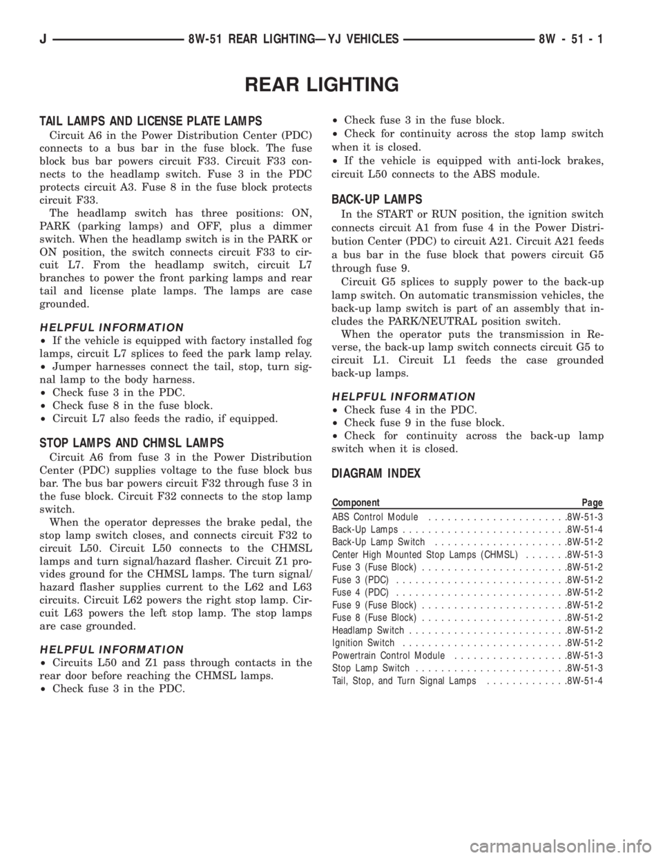
Circuit A6 in the Power Distribution Center (PDC)
connects to a bus bar in the fuse block. The fuse
block bus bar powers circuit F33. Circuit F33 con-
nects to the headlamp switch. Fuse 3 in the PDC
protects circuit A3. Fuse 8 in the fuse block protects
circuit F33.
The headlamp switch has three positions: ON,
PARK (parking lamps) and OFF, plus a dimmer
switch. When the headlamp switch is in the PARK or
ON position, the switch connects circuit F33 to cir-
cuit L7. From the headlamp switch, circuit L7
branches to power the front parking lamps and rear
tail and license plate lamps. The lamps are case
grounded.
HELPFUL INFORMATION
²If the vehicle is equipped with factory installed fog
lamps, circuit L7 splices to feed the park lamp relay.
²Jumper harnesses connect the tail, stop, turn sig-
nal lamp to the body harness.
²Check fuse 3 in the PDC.
²Check fuse 8 in the fuse block.
²Circuit L7 also feeds the radio, if equipped.
STOP LAMPS AND CHMSL LAMPS
Circuit A6 from fuse 3 in the Power Distribution
Center (PDC) supplies voltage to the fuse block bus
bar. The bus bar powers circuit F32 through fuse 3 in
the fuse block. Circuit F32 connects to the stop lamp
switch.
When the operator depresses the brake pedal, the
stop lamp switch closes, and connects circuit F32 to
circuit L50. Circuit L50 connects to the CHMSL
lamps and turn signal/hazard flasher. Circuit Z1 pro-
vides ground for the CHMSL lamps. The turn signal/
hazard flasher supplies current to the L62 and L63
circuits. Circuit L62 powers the right stop lamp. Cir-
cuit L63 powers the left stop lamp. The stop lamps
are case grounded.
HELPFUL INFORMATION
²Circuits L50 and Z1 pass through contacts in the
rear door before reaching the CHMSL lamps.
²Check fuse 3 in the PDC.²Check fuse 3 in the fuse block.
²Check for continuity across the stop lamp switch
when it is closed.
²If the vehicle is equipped with anti-lock brakes,
circuit L50 connects to the ABS module.
BACK-UP LAMPS
In the START or RUN position, the ignition switch
connects circuit A1 from fuse 4 in the Power Distri-
bution Center (PDC) to circuit A21. Circuit A21 feeds
a bus bar in the fuse block that powers circuit G5
through fuse 9.
Circuit G5 splices to supply power to the back-up
lamp switch. On automatic transmission vehicles, the
back-up lamp switch is part of an assembly that in-
cludes the PARK/NEUTRAL position switch.
When the operator puts the transmission in Re-
verse, the back-up lamp switch connects circuit G5 to
circuit L1. Circuit L1 feeds the case grounded
back-up lamps.
HELPFUL INFORMATION
²Check fuse 4 in the PDC.
²Check fuse 9 in the fuse block.
²Check for continuity across the back-up lamp
switch when it is closed.
DIAGRAM INDEX
Component Page
ABS Control Module......................8W-51-3
Back-Up Lamps..........................8W-51-4
Back-Up Lamp Switch.....................8W-51-2
Center High Mounted Stop Lamps (CHMSL).......8W-51-3
Fuse 3 (Fuse Block).......................8W-51-2
Fuse 3 (PDC)...........................8W-51-2
Fuse 4 (PDC)...........................8W-51-2
Fuse 9 (Fuse Block).......................8W-51-2
Fuse 8 (Fuse Block).......................8W-51-2
Headlamp Switch.........................8W-51-2
Ignition Switch..........................8W-51-2
Powertrain Control Module..................8W-51-3
Stop Lamp Switch........................8W-51-3
Tail, Stop, and Turn Signal Lamps.............8W-51-4
J8W-51 REAR LIGHTINGÐYJ VEHICLES 8W - 51 - 1
Page 2166 of 2198
CONNECTOR LOCATIONS
GENERAL INFORMATION
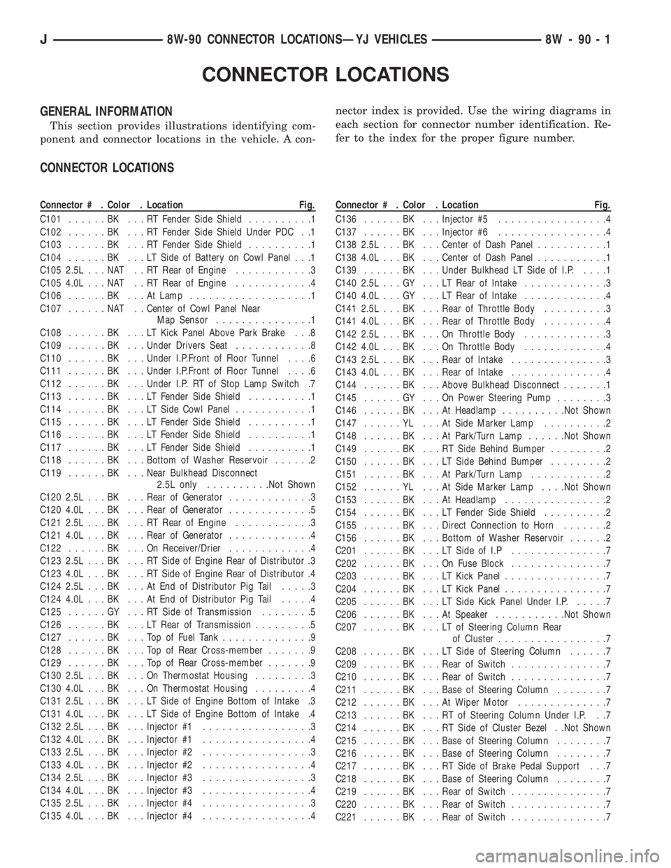
This section provides illustrations identifying com-
ponent and connector locations in the vehicle. A con-nector index is provided. Use the wiring diagrams in
each section for connector number identification. Re-
fer to the index for the proper figure number.
CONNECTOR LOCATIONS
Connector # . Color . Location Fig.
C101......BK ...RTFender Side Shield..........1
C102......BK ...RTFender Side Shield Under PDC . .1
C103......BK ...RTFender Side Shield..........1
C104......BK ...LTSide of Battery on Cowl Panel . . .1
C105 2.5L . . . NAT . . RT Rear of Engine............3
C105 4.0L . . . NAT . . RT Rear of Engine............4
C106......BK ...AtLamp...................1
C107......NAT ..Center of Cowl Panel Near
Map Sensor...............1
C108......BK ...LTKick Panel Above Park Brake . . .8
C109......BK ...Under Drivers Seat............8
C110......BK ...Under I.P.Front of Floor Tunnel....6
C111......BK ...Under I.P.Front of Floor Tunnel....6
C112......BK ...Under I.P. RT of Stop Lamp Switch .7
C113......BK ...LTFender Side Shield..........1
C114......BK ...LTSide Cowl Panel............1
C115......BK ...LTFender Side Shield..........1
C116......BK ...LTFender Side Shield..........1
C117......BK ...LTFender Side Shield..........1
C118......BK ...Bottom of Washer Reservoir......2
C119......BK ...Near Bulkhead Disconnect
2.5L only..........Not Shown
C120 2.5L . . . BK . . . Rear of Generator.............3
C120 4.0L . . . BK . . . Rear of Generator.............5
C121 2.5L . . . BK . . . RT Rear of Engine............3
C121 4.0L . . . BK . . . Rear of Generator.............4
C122......BK ...OnReceiver/Drier.............4
C123 2.5L . . . BK . . . RT Side of Engine Rear of Distributor .3
C123 4.0L . . . BK . . . RT Side of Engine Rear of Distributor .4
C124 2.5L . . . BK . . . At End of Distributor Pig Tail.....3
C124 4.0L . . . BK . . . At End of Distributor Pig Tail.....4
C125......GY ...RTSide of Transmission........5
C126......BK ...LTRear of Transmission.........5
C127......BK ...TopofFuel Tank..............9
C128......BK ...TopofRear Cross-member.......9
C129......BK ...TopofRear Cross-member.......9
C130 2.5L . . . BK . . . On Thermostat Housing.........3
C130 4.0L . . . BK . . . On Thermostat Housing.........4
C131 2.5L . . . BK . . . LT Side of Engine Bottom of Intake .3
C131 4.0L . . . BK . . . LT Side of Engine Bottom of Intake .4
C132 2.5L . . . BK . . . Injector #1.................3
C132 4.0L . . . BK . . . Injector #1.................4
C133 2.5L . . . BK . . . Injector #2.................3
C133 4.0L . . . BK . . . Injector #2.................4
C134 2.5L . . . BK . . . Injector #3.................3
C134 4.0L . . . BK . . . Injector #3.................4
C135 2.5L . . . BK . . . Injector #4.................3
C135 4.0L . . . BK . . . Injector #4.................4Connector # . Color . Location Fig.
C136......BK ...Injector #5.................4
C137......BK ...Injector #6.................4
C138 2.5L . . . BK . . . Center of Dash Panel...........1
C138 4.0L . . . BK . . . Center of Dash Panel...........1
C139......BK ...Under Bulkhead LT Side of I.P.....1
C140 2.5L . . . GY . . . LT Rear of Intake.............3
C140 4.0L . . . GY . . . LT Rear of Intake.............4
C141 2.5L . . . BK . . . Rear of Throttle Body..........3
C141 4.0L . . . BK . . . Rear of Throttle Body..........4
C142 2.5L . . . BK . . . On Throttle Body.............3
C142 4.0L . . . BK . . . On Throttle Body.............4
C143 2.5L . . . BK . . . Rear of Intake...............3
C143 4.0L . . . BK . . . Rear of Intake...............4
C144......BK ...Above Bulkhead Disconnect.......1
C145......GY ...OnPower Steering Pump........3
C146......BK ...AtHeadlamp..........Not Shown
C147......YL ...AtSide Marker Lamp..........2
C148......BK ...AtPark/Turn Lamp......Not Shown
C149......BK ...RTSide Behind Bumper.........2
C150......BK ...LTSide Behind Bumper.........2
C151......BK ...AtPark/Turn Lamp............2
C152......YL ...AtSide Marker Lamp. . . .Not Shown
C153......BK ...AtHeadlamp................2
C154......BK ...LTFender Side Shield..........2
C155......BK ...Direct Connection to Horn.......2
C156......BK ...Bottom of Washer Reservoir......2
C201......BK ...LTSide of I.P...............7
C202......BK ...OnFuse Block...............7
C203......BK ...LTKick Panel................7
C204......BK ...LTKick Panel................7
C205......BK ...LTSide Kick Panel Under I.P......7
C206......BK ...AtSpeaker...........Not Shown
C207......BK ...LTofSteering Column Rear
of Cluster.................7
C208......BK ...LTSide of Steering Column......7
C209......BK ...Rear of Switch...............7
C210......BK ...Rear of Switch...............7
C211......BK ...Base of Steering Column........7
C212......BK ...AtWiper Motor..............7
C213......BK ...RTofSteering Column Under I.P. . .7
C214......BK ...RTSide of Cluster Bezel . .Not Shown
C215......BK ...Base of Steering Column........7
C216......BK ...Base of Steering Column........7
C217......BK ...RTSide of Brake Pedal Support . . .7
C218......BK ...Base of Steering Column........7
C219......BK ...Rear of Switch...............7
C220......BK ...Rear of Switch...............7
C221......BK ...Rear of Switch...............7
J8W-90 CONNECTOR LOCATIONSÐYJ VEHICLES 8W - 90 - 1
Page 2167 of 2198
Connector # . Color . Location Fig.
C222......BK ...Rear of Switch...............6
C223......BK ...Rear of HVAC Switch...........6
C224......BK ...Rear of Radio...............6
C225......BK ...Rear Center of I.P.............6
C226......BK ...Rear of Glove Box LT Side.......6
C227......BK ...Under I.P Right Side...........6
C228......BK ...AtSpeaker...........Not Shown
C229......BK ...RTSide of HVAC Housing.......6
C230......BK ...RTSide of HVAC Housing.......6
C231......BK ...RTKick Panel.............6,7
C232......BK ...TopofI.P.Center Support.......7
C233......BK ...TopofI.P.Center Support.......7
C301......RD ...LTKick Panel................8
C302......BK ...AtBuckle..................8
C303......BK ...LTRear Quarter Panel..........8
C304......BK ...LTRear Quarter Panel..........8
C305......BK ...RTRear Quarter Panel..........8
C306......BK ...AtMotor............Not Shown
C307......BK ...LTSide of I.P. at Lamp.........6
C308......BK ...RTSide of I.P. at Lamp.........7
C309......BK ...AtCHMSL Lamp.......Not Shown
C310......BK ...AtCHMSL Lamp.......Not Shown
C401......BK ...TopofFuel Tank..............9Connector # . Color . Location Fig.
C402......BK ...RTSide of Axle........Not Shown
C403......BK ...RTSide of Roll Bar............8
C404......GY ...LTSide Front of Transmission.....5
C405......BK ...RTSide of Transmission........5
D101............ABSDiode Under I.P.Front of
Floor Tunnel...............6
D201............Taped In Harness Near Wiper
Switch T/O................6
G101............Left of Battery on Dash Panel.....1
G102............Center of Dash Panel...........1
G103 2.5L . .......Rear of Distributor............3
G103 4.0L . .......Rear of Generator.............4
G104 2.5L . .......RTSide of Engine.............3
G104 4.0L . .......RtSide of Engine.............4
G105............RTSide Radiator Closure Panel....2
G106............LTSide Radiator Closure Panel....2
G107............RTSide of Dash Panel.........1
G108 2.5L . .......RTRear of Engine............3
G108 4.0L . .......RTRear of Engine............4
G201.............AtCigar Lighter..............6
G202.............Rear of Radio...............6
8W - 90 - 2 8W-90 CONNECTOR LOCATIONSÐYJ VEHICLESJ
Page 2172 of 2198
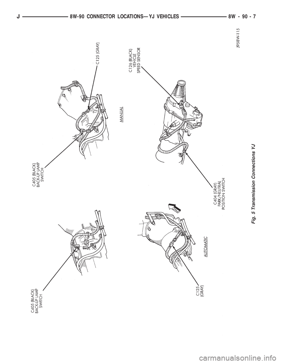
Fig. 5 Transmission Connections YJ
J8W-90 CONNECTOR LOCATIONSÐYJ VEHICLES 8W - 90 - 7
Page 2182 of 2198
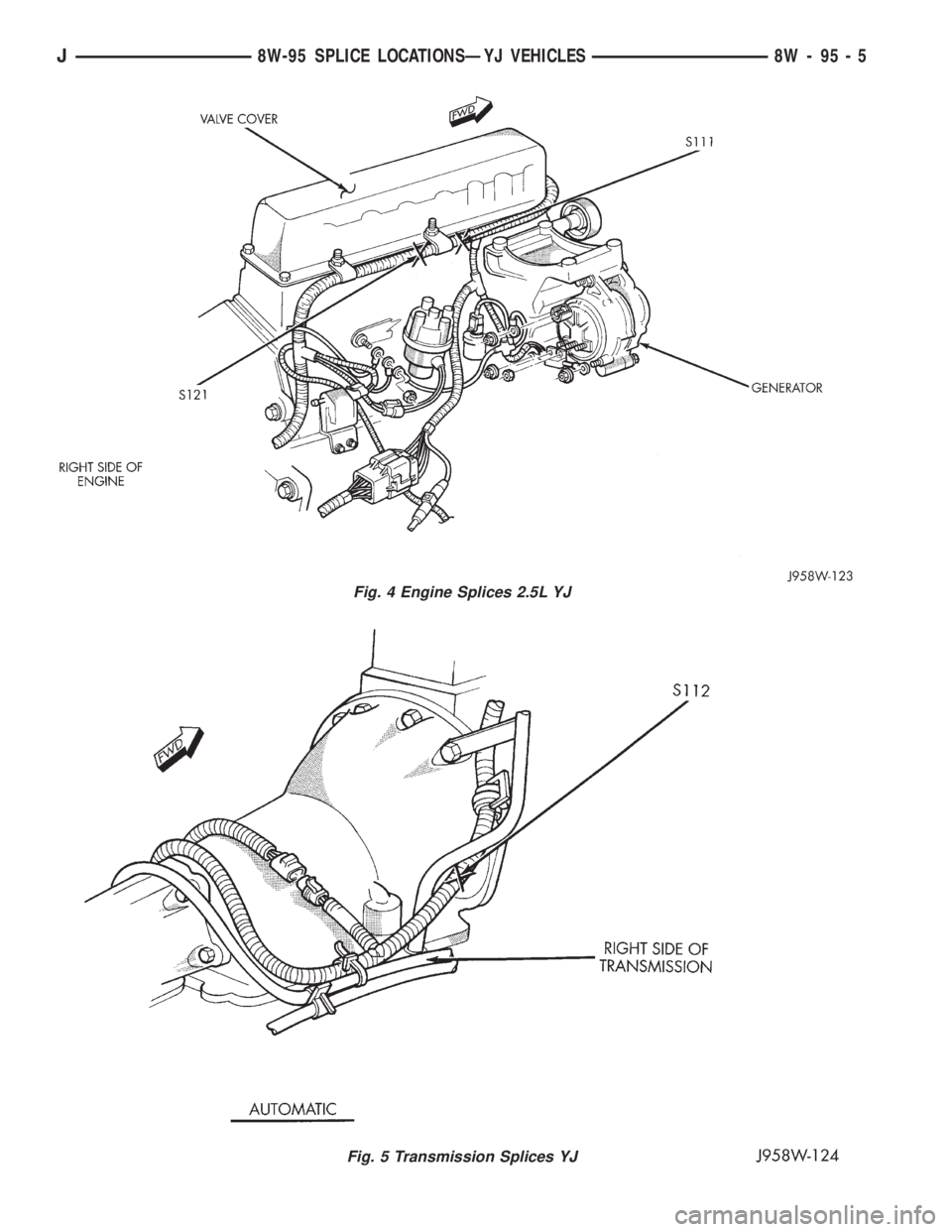
Fig. 4 Engine Splices 2.5L YJ
Fig. 5 Transmission Splices YJ
J8W-95 SPLICE LOCATIONSÐYJ VEHICLES 8W - 95 - 5