1995 JEEP CHEROKEE transmission
[x] Cancel search: transmissionPage 602 of 2198
DIAGRAM INDEX
Component Page
ABS Control Module..................8W-32-4 thru 8
ABS Hydraulic Unit.......................8W-32-6
ABS Power Relay........................8W-32-4
ABS Pump Motor........................8W-32-5
ABS Pump Motor Relay....................8W-32-4
Data Link Connector......................8W-32-8
Diode................................8W-32-6
Fuse 6 (PDC)...........................8W-32-5
Fuse 7 (Fuse Block).......................8W-32-5
Fuse 7 (PDC)...........................8W-32-8
Fuse 8 (PDC)...........................8W-32-5
Fuse 10 (PDC)..........................8W-32-4
Fuse 13 (PDC)..........................8W-32-8
G-Sensor..............................8W-32-8
Ignition Switch..........................8W-32-5
Powertrain Control Module..................8W-32-8
Telltale Connector (Instrument Cluster)...........8W-32-6
Transmission Control Module.................8W-32-8
Wheel Speed Sensors......................8W-32-7
J8W-32 ANTI-LOCK BRAKESÐXJ VEHICLES 8W - 32 - 3
Page 608 of 2198
VEHICLE SPEED CONTROL
VEHICLE SPEED CONTROL
The vehicle speed control system is operated by the
Powertrain Control Module (PCM). Circuit F12 from
fuse 11 in the Power Distribution Center (PDC) sup-
plies battery voltage to the vehicle speed control ON/
OFF switch. Circuit A21 supplies voltage to fuse 11
when the ignition switch is in the START or RUN po-
sitions. In the START or RUN position the ignition
switch connects circuit A21 with circuit A1. Fuse 6 in
the PDC protects circuit A1.
The vehicle speed control ON/OFF switch supplies
voltage to the SET/COAST and RESUME/ACCEL
switches. Both switches send signals to the PCM
(which supplies the ground path for the switches).
The PCM controls the vent and vacuum functions
of the speed control servo on circuits V35 and V36.
Depending on the signal it receives from the vehicle
speed control switches, the PCM either applies vac-
uum to, or vents vacuum from, the servo. Circuit V36
from cavity 33 of the PCM sends the vacuum signal
to the servo. Circuit V35 from cavity 53 sends the
vent signal.
Circuit V32 signals to the PCM that the speed con-
trol switch is in the ON position. The V32 circuit con-
nects to cavity 49 of the PCM. Circuit V32 also
connects to the stop lamp switch.
In the CLOSED position, the stop lamp switch con-
nects circuit V32 with circuit V30 to power the speed
control servo. Circuit Z1 provides ground for the
speed control servo.
Circuit V31 provides the SET/COAST signal to cav-
ity 48 of the PCM. Circuit V33 sends the RESUME/
ACCEL signal to cavity 50 of the PCM.
Circuit K29 connects to cavity 29 of the PCM and
to ground through the stop lamp switch. The stop
lamp switch OPENS when the operator depresses the
brake pedal. The PCM disables speed control when
the stop lamp switch opens. From the stop lamp
switch, circuit Z1 provides ground for circuit K29.
HELPFUL INFORMATION
²Circuit K29 also connects to the ABS control mod-
ule on vehicles with all wheel anti-lock brakes.
²On vehicles with the 4.0L Engine and Automatic
Transmission, Circuit K29 connects to the Transmis-
sion Control Module (TCM).
DIAGRAM INDEX
Component Page
ABS Control Module..................8W-32-4 thru 8
ABS Hydraulic Unit.......................8W-32-6
ABS Power Relay........................8W-32-4
ABS Pump Motor........................8W-32-5
ABS Pump Motor Relay....................8W-32-4
Data Link Connector......................8W-32-8
Diode................................8W-32-6
Fuse 6 (PDC)...........................8W-32-5
Fuse 7 (Fuse Block).......................8W-32-5
Fuse 7 (PDC)...........................8W-32-8
Fuse 8 (PDC)...........................8W-32-5
Fuse 10 (PDC)..........................8W-32-4
Fuse 13 (PDC)..........................8W-32-8
G-Sensor..............................8W-32-8
Ignition Switch..........................8W-32-5
Powertrain Control Module..................8W-32-8
Telltale Connector (Instrument Cluster)...........8W-32-6
Transmission Control Module.................8W-32-8
Wheel Speed Sensors......................8W-32-7
J8W-33 VEHICLE SPEED CONTROLÐXJ VEHICLES 8W - 33 - 1
Page 612 of 2198
INSTRUMENT CLUSTER
INDEX
page page
ABS Warning Lamp........................ 2
Brake Warning Lamp....................... 2
Charging System Indicator Lamp............... 3
Cluster Ground............................ 3
Diagram Index............................. 3
Engine Coolant Temperature Gauge............ 1
Engine Coolant Temperature Warning Lamp...... 1
Fuel Gauge.............................. 1
High-Beam Indicator Lamp................... 2
Instrument Cluster......................... 1Low Fuel Warning Lamp..................... 1
Low Washer Fluid Warning Lamp.............. 2
Malfunction Indicator Lamp (MIL)............... 2
Manual Transmission Up-Shift Lamp............ 2
Oil Pressure Gauge........................ 2
Oil Pressure Warning Lamp.................. 2
Seat Belt Indicator Warning Lamp.............. 2
Speedometer............................. 2
Tachometer.............................. 2
Turn Signal Indicator Lamps.................. 2
INSTRUMENT CLUSTER
The instrument cluster contains the gauges and
warning lamps. All gauges have magnetic move-
ments.
When the ignition switch is in the START or RUN
position, circuit A21 feeds circuit F87 through fuse 17
in the fuse block. Circuit A1 from fuse 6 in the Power
Distribution Center (PDC) supplies voltage to circuit
A21. Circuit A1 is HOT at all times.
Circuit F87 connects to the cluster connector to
power the gauges and to the telltale connector to
power the warning lamps.
Circuit E2 from fuse 19 in the fuse block feeds the
illumination lamps. Circuit E2 originates at the head-
lamp switch and continues through fuse 19. The
headlamp switch powers circuit E2 when the parking
lamps or headlamp are ON.
Circuit Z2 provides ground for the indicator lamps
and illumination lamps.
ENGINE COOLANT TEMPERATURE GAUGE
Circuit G20 connects the engine coolant tempera-
ture gauge to the engine coolant temperature sensor.
The sensor is a variable resistor and case grounded to
the engine. Circuit F87 connects to the instrument
cluster left connector and supplies voltage for the
gauge.
The gauge uses two coils. Current passing through
the coils creates a magnetic field. Position of the
gauge needle is controlled by the amount of current
passing through the coils to ground at the sensor.
ENGINE COOLANT TEMPERATURE WARNING
LAMP
Circuit G20 connects the engine coolant tempera-
ture warning lamp to the engine coolant temperature
switch. When the switch closes, battery voltage from
circuit F87 flows through the lamp to ground through
the switch on circuit G20. The engine coolant tem-
perature switch is case grounded to the engine. Cir-cuit F87 connects to the instrument cluster connector
and supplies voltage for the lamp.
Circuit G20 also connects to the warning lamp to
ground when the ignition switch is in the START
position. When the ignition switch is in the START
position, the lamp illuminates for a bulb test.
FUEL GAUGE
The fuel level sensor is a variable resistor. Circuit
G4 connects the fuel level sensor to the fuel gauge in
the instrument cluster. Circuit F87 from fuse 17 in
the fuse block supplies voltage to the fuel gauge. The
fuel level sensor draws voltage from circuit F87
through the fuel gauge on circuit G4. Circuit G4
connects to circuit 57 in the fuel pump module har-
ness. Circuit 57 connects to the fuel level sensor.
Circuit 99 in the fuel pump module harness con-
nects to circuit Z1. Circuit Z1 provides the ground
path for the fuel level sensor. The grounding point for
circuit Z1 is the left side of the cowl panel.
As current flows through the coils in the fuel gauge,
it creates a magnetic field. One of the coils in the
gauge receives fixed current. The other coil is con-
nected to the level sensor. The magnetic field controls
the position of the fuel gauge pointer.
The fuel level sensor contains a variable resistor. As
the position of the float arm on the fuel level sensor
changes, the resistor changes the current flow
through second coil in the fuel gauge. A change in
current flow alters the magnetic field in the fuel
gauge, which changes the pointer position.
LOW FUEL WARNING LAMP
Circuit G4 connects the fuel level sensor to the fuel
gauge. The low fuel level module at the rear of the
gauge monitors resistance in circuit G4. The low fuel
level module powers an light emitting diode (LED)
when the resistance in circuit G4 reaches a calibrated
level. The LED illuminates the Low Fuel indicator.
Refer to Group 8E for additional information.
J8W-40 INSTRUMENT CLUSTERÐXJ VEHICLES 8W - 40 - 1
Page 613 of 2198
OIL PRESSURE GAUGE
The case grounded oil pressure sensor is a variable
resistor that connects to circuit G6. Circuit G6 con-
nects to the oil pressure gauge.
Circuit F87 connects to the instrument cluster con-
nector and supplies battery voltage to oil pressure
gauge. The gauge uses two coils. Current passing
through the coils creates a magnetic field. Position of
the gauge needle is controlled by the amount of cur-
rent passing through the coils to ground at the sen-
sor.
OIL PRESSURE WARNING LAMP
The case grounded oil pressure switch connects to
circuit G6. Circuit G6 connects to the oil pressure
warning lamp. Circuit F87 connects to the instru-
ment cluster connector and supplies battery voltage
to oil pressure lamp.
When the oil pressure switch close, battery voltage
flows through the warning lamp to ground through
the switch, illuminating the lamp.
TACHOMETER
The tachometer module in the instrument cluster
operates the tachometer. The Powertrain Control
Module (PCM) supplies the signal for the tachometer
on circuit G21. Circuit G21 connects to cavity 43 of
the PCM.
SPEEDOMETER
The speedometer and odometer receive a signal
from the vehicle speed sensor on circuit G7. Circuit
G7 also connects to the Powertrain Control Module
(PCM) at cavity 47.
ABS WARNING LAMP
Circuit F87 provides power for the ABS warning
lamp at the instrument cluster. Ground for the ABS
warning lamp is provided by either the ABS control
module or by the ABS power relay when the relay is
not energized. The ABS control module illuminates
the lamp by providing ground on circuit B205.
Circuit B205 splices to connect to circuit B235
through a diode. When the ABS power relay is not
energized, it connects circuit B235 to circuit Z12. The
ground path for the warning lamp is through the di-
ode to circuit B235, through the ABS power relay to
ground on circuit Z12.
The diode between circuit B205 and B235 prevents
voltage from flowing to the ABS control module when
the ABS power relay switches to supply power on cir-
cuit B235.
MALFUNCTION INDICATOR LAMP (MIL)
The PCM provides ground for the instrument clus-
ter malfunction indicator lamp on circuit G3. Circuit
G3 connects to cavity 32 of the PCM. Circuit F87provides voltage for the lamp. The MIL displays the
message CHECK ENGINE when illuminated.
For information regarding diagnostic trouble code
access using the MIL lamp, refer to Group 14, Fuel
Systems.
LOW WASHER FLUID WARNING LAMP
Circuit G29 connects the low washer fluid switch to
the warning lamp in the instrument cluster. Circuit
F12 supplies battery voltage to the switch.
When the low washer fluid switch closes, it con-
nects circuits G29 and F12. Battery voltage from cir-
cuit F12 powers the low washer fluid lamp. Circuit
Z1 at the instrument cluster provides ground to illu-
minate the warning lamp.
SEAT BELT INDICATOR WARNING LAMP
The seat belt indicator warning lamp is activated
by the chime/buzzer on circuit G11. Circuit G11 sup-
plies power to instrument cluster for the lamp. Cir-
cuit Z1 provides ground for the lamp at the cluster.
The chime/buzzer module powers circuit G11 after
it receives an input on circuit G10 indicating the seat
belt switch is open.
HIGH-BEAM INDICATOR LAMP
Circuit L3 supplies power for the high-beam indi-
cator lamp. The ground path for the lamp is through
circuit Z1. If the vehicle has Daytime Running
Lamps (DRL), the DRL module powers circuit L3
through circuit G465. On vehicles not equipped with
DRL, the headlamp switch powers circuit L3.
Circuit Z1 provides ground for the indicator lamp
at the cluster.
TURN SIGNAL INDICATOR LAMPS
Circuits L61 and L60 power for the turn signal in-
dicator lamps. Circuit L61 powers the left indicator
lamp. Circuit L60 powers the right indicator lamp.
Circuit Z1 provides ground for the lamps.
BRAKE WARNING LAMP
Circuit F87 supplies power to the park brake lamp.
Ground for the park brake lamp is supplied through
the case grounded park brake switch or brake warn-
ing switch on circuit G9. Circuit G9 Connects to cir-
cuit B203. Circuit B203 connects to the brake
warning lamp at the instrument cluster.
MANUAL TRANSMISSION UP-SHIFT LAMP
Circuit F87 supplies power for the manual trans-
mission up-shift lamp. The lamp illuminates when
the Powertrain Control Module (PCM) provides
ground for the lamp on circuit K54. Circuit K54 con-
nects to cavity 54 of the PCM.
8W - 40 - 2 8W-40 INSTRUMENT CLUSTERÐXJ VEHICLESJ
Page 632 of 2198

INTERIOR LIGHTING
INDEX
page page
Cargo Lamp, Courtesy Lamps and Dome Lamp.... 1
Chime/Buzzer Module....................... 2
Diagram Index............................ 2
General Information........................ 1
Glove Box Lamp........................... 1
Ignition Switch Lamp........................ 1Instrument Panel Illumination Lamps............ 1
Reading Lamps........................... 2
Time Delay Relay.......................... 1
Underhood Lamp.......................... 2
Visor Vanity Mirror Lamps.................... 2
GENERAL INFORMATION
Circuit M1 supplies power to the glove box lamp,
left courtesy lamp, right courtesy lamp, dome lamp,
and cargo lamp. The M1 circuit also connects to the
remote keyless entry module. Circuit M1 is protected
by the ignition off draw (IOD) fuse (fuse 9) in the fuse
block.
Circuit E2 supplies power for the instrument panel
illumination lamps.
INSTRUMENT PANEL ILLUMINATION LAMPS
Circuit E2 from the headlamp switch splices to
supply power to the following illumination lamps:
²Ash receiver lamp
²Cigar lighter lamp
²Transmission range indicator lamp
²Transfer case range indicator lamp
²A/C-Heater switch lamp
²Heated rear window lamp
²Rear wiper switch lamp
²Fog lamp switch lamp
Fuse 19 in the fuse block protects circuit E2. Circuit
Z1 provides ground for all of the illumination lamps
except for the cigar lighter lamp. The cigar lighter
lamp is case grounded.
HELPFUL INFORMATION
Circuit E2 also supplies power to the radio, LCD
relay and the illumination lamps in the instrument
cluster.
IGNITION SWITCH LAMP
The time delay relay is used to allow a time-ON
function for the ignition switch lamp and the courtesy
lamp. Power for the relay is received on the M1
circuit from the IOD fuse (fuse F9) in the fuse block.
Circuit M2 provides ground for the time delay relay
through the right and left door ajar switches and the
headlamp switch. When a door is opened, or the
headlamp switch is moved to the dome lamp position,a ground path is provided for the relay on circuit M2.
This energizes the relay, causing the contacts to close.
When the relay contacts close, power is provided
through the relay to circuit M50. The M50 circuit
supplies current to the ignition switch lamp. Circuit
Z1 provides ground for the lamp.
GLOVE BOX LAMP
Circuit M1 from the IOD fuse (fuse F9) in the fuse
block powers the glove box lamp. A case grounded
switch, in series after the lamp, closes when the glove
box door is opened. The switch completes a path to
ground on circuit Z1.
CARGO LAMP, COURTESY LAMPS AND DOME
LAMP
Circuit M1 from the IOD fuse (fuse F9) in the fuse
block supplies power to the cargo, courtesy lamps and
dome lamp. This circuit is HOT at all times. The
ground path for the lamp is provided in three differ-
ent ways.
One way is through the door jamb switches. Circuit
M2 connects to the door jamb switches from the cour-
tesy and dome lamps. The switches are connected to
ground circuit Z1. When a door is opened, the plunger
in the switch closes, completing a path to ground.
The second way is through the liftgate switch. Cir-
cuit M2 connects to circuit M4 at the cargo lamp.
Circuit M4 connects to the liftgate switch. The lift-
gate switch connects to ground circuit Z1. When the
lift gate opens, the plunger in the switch closes, com-
pleting a path to ground.
The third ground path is through the headlamp
switch. Circuit M2 is spliced in with the headlamp
switch. When the operator turns the headlamp switch
to the dome lamp ON position, a ground path is
provided through the switch.
J8W-44 INTERIOR LIGHTINGÐXJ VEHICLES 8W - 44 - 1
Page 670 of 2198
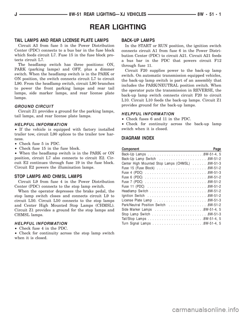
REAR LIGHTING
TAIL LAMPS AND REAR LICENSE PLATE LAMPS
Circuit A3 from fuse 5 in the Power Distribution
Center (PDC) connects to a bus bar in the fuse block
which feeds circuit L7. Fuse 15 in the fuse block pro-
tects circuit L7.
The headlamp switch has three positions: ON,
PARK (parking lamps) and OFF, plus a dimmer
switch. When the headlamp switch is in the PARK or
ON position, the switch connects circuit L7 to circuit
L90. From the headlamp switch, circuit L90 branches
to power the front parking lamps and rear tail
lamps, side marker lamps, and rear license plate
lamps.
GROUND CIRCUIT
Circuit Z1 provides a ground for the parking lamps,
tail lamps, and rear license plate lamps.
HELPFUL INFORMATION
²If the vehicle is equipped with factory installed
trailer tow, circuit L90 splices to the trailer tow har-
ness.
²Check fuse 5 in PDC.
²Check fuse 15 in the fuse block.
²When the headlamp switch is in the PARK or ON
position, circuit L7 also connects to circuit E2. Cir-
cuit E2 continues through fuse 19 in the fuse block.
Circuit E2 powers the illumination lamps.
STOP LAMPS AND CHMSL LAMPS
Circuit L9 from fuse 4 in the Power Distribution
Center (PDC) connects to the stop lamp switch.
When the operator depresses the brake pedal, the
stop lamp switch closes and connects circuit L9 to
circuit L50. Circuit L50 connects to the stop lamps
and Center High Mounted Stop Lamps (CHMSL).
Circuit Z1 provides a ground for the stop lamps and
CHMSL lamps.
HELPFUL INFORMATION
²Check fuse 4 in the PDC.
²Check for continuity across the stop lamp switch
when it is closed.
BACK-UP LAMPS
In the START or RUN position, the ignition switch
connects circuit A1 from fuse 6 in the Power Distri-
bution Center (PDC) to circuit A21. Circuit A21 feeds
a bus bar in the PDC that powers circuit F12
through fuse 11.
Circuit F20 supplies power to the back-up lamp
switch. On automatic transmission equipped vehicles,
the back-up lamp switch is part of an assembly that
includes the PARK/NEUTRAL position switch. When
the operator puts the transmission in REVERSE, the
back-up lamp switch connects circuit F20 to circuit
L10. Circuit L10 feeds the back-up lamps. Circuit Z1
provides ground for the back-up lamps.
HELPFUL INFORMATION
²Check fuses 6 and 11 in the PDC.
²Check for continuity across the back-up lamp
switch when it is closed.
DIAGRAM INDEX
Component Page
Back-Up Lamps........................8W-51-4, 5
Back-Up Lamp Switch.....................8W-51-2
Center High Mounted Stop Lamps (CHMSL).......8W-51-3
Fuse 15 (Fuse Block)......................8W-51-2
Fuse 4 (PDC)...........................8W-51-3
Fuse 6 (PDC)...........................8W-51-2
Fuse 7 (PDC)...........................8W-51-2
Fuse 11 (PDC)..........................8W-51-2
Headlamp Switch.........................8W-51-2
Ignition Switch..........................8W-51-2
License Plate Lamp.......................8W-51-3
Park/Neutral Position Switch.................8W-51-2
Side Marker Lamps.....................8W-51-4, 5
Stop Lamp Switch........................8W-51-3
Tail/Stop Lamps........................8W-51-4, 5
Turn Signal Lamps......................8W-51-4, 5
J8W-51 REAR LIGHTINGÐXJ VEHICLES 8W - 51 - 1
Page 676 of 2198
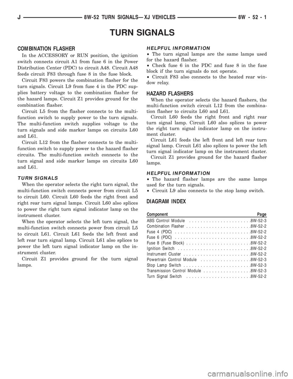
TURN SIGNALS
COMBINATION FLASHER
In the ACCESSORY or RUN position, the ignition
switch connects circuit A1 from fuse 6 in the Power
Distribution Center (PDC) to circuit A48. Circuit A48
feeds circuit F83 through fuse 8 in the fuse block.
Circuit F83 powers the combination flasher for the
turn signals. Circuit L9 from fuse 4 in the PDC sup-
plies battery voltage to the combination flasher for
the hazard lamps. Circuit Z1 provides ground for the
combination flasher.
Circuit L5 from the flasher connects to the multi-
function switch to supply power to the turn signals.
The multi-function switch supplies voltage to the
turn signals and side marker lamps on circuits L60
and L61.
Circuit L12 from the flasher connects to the multi-
function switch to supply power to the hazard flasher
circuits. The multi-function switch connects to the
turn signal and side marker lamps on circuits L60
and L61.
TURN SIGNALS
When the operator selects the right turn signal, the
multi-function switch connects power from circuit L5
to circuit L60. Circuit L60 feeds the right front and
right rear turn signal lamps. Circuit L60 also splices
to power the right turn signal indicator lamp on the
instrument cluster.
When the operator selects the left turn signal, the
multi-function switch connects power from circuit L5
to circuit L61. Circuit L61 feeds the left front and
left rear turn signal lamp. Circuit L61 also splices to
power the left turn signal indicator lamp on the in-
strument cluster.
Circuit Z1 provides ground for the turn signal
lamps.
HELPFUL INFORMATION
²The turn signal lamps are the same lamps used
for the hazard flasher.
²Check fuse 6 in the PDC and fuse 8 in the fuse
block if the turn signals do not operate.
²Circuit F83 also connects to the heated rear win-
dow relay.
HAZARD FLASHERS
When the operator selects the hazard flashers, the
multi-function switch circuit L12 from the combina-
tion flasher to circuits L60 and L61.
Circuit L60 feeds the right front and right rear
turn signal lamp. Circuit L60 also splices to power
the right turn signal indicator lamp on the instru-
ment cluster.
Circuit L61 feeds the left front and left rear turn
signal lamp. Circuit L61 also splices to power the left
turn signal indicator lamp on the instrument cluster.
Circuit Z1 provides ground for the hazard flasher
lamps.
HELPFUL INFORMATION
²The hazard flasher lamps are the same lamps
used for the turn signals.
²Circuit L9 also connects to the stop lamp switch.
DIAGRAM INDEX
Component Page
ABS Control Module......................8W-52-3
Combination Flasher.......................8W-52-2
Fuse 4 (PDC)...........................8W-52-2
Fuse 6 (PDC)...........................8W-52-2
Fuse 8 (Fuse Block).......................8W-52-2
Ignition Switch..........................8W-52-2
Instrument Cluster........................8W-52-2
Powertrain Control Module..................8W-52-3
Stop Lamp Switch........................8W-52-3
Transmission Control Module.................8W-52-3
Turn Signal Switch.......................8W-52-2
J8W-52 TURN SIGNALSÐXJ VEHICLES 8W - 52 - 1
Page 780 of 2198
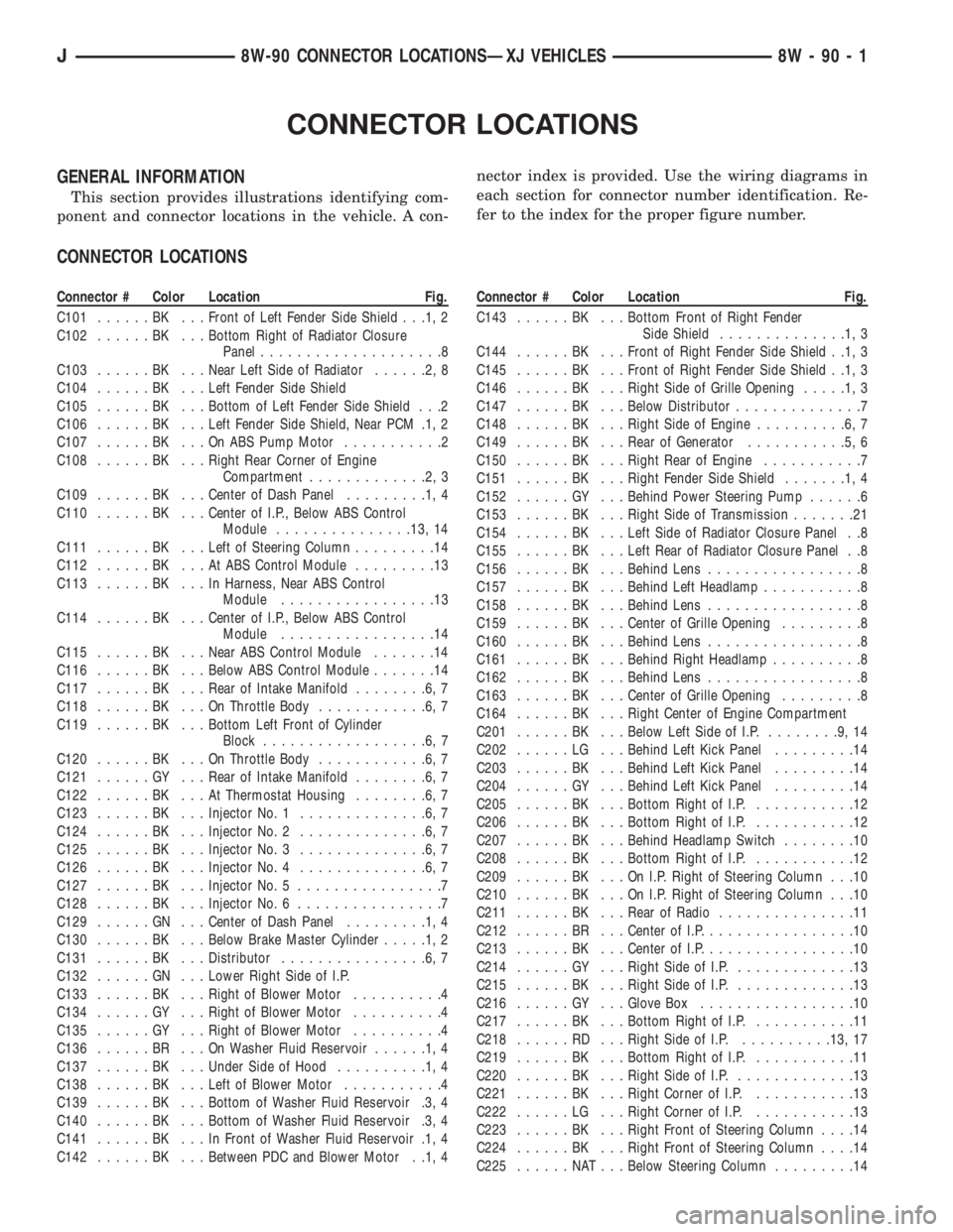
CONNECTOR LOCATIONS
GENERAL INFORMATION
This section provides illustrations identifying com-
ponent and connector locations in the vehicle. A con-nector index is provided. Use the wiring diagrams in
each section for connector number identification. Re-
fer to the index for the proper figure number.
CONNECTOR LOCATIONS
Connector # Color Location Fig.
C101......BK ...Front of Left Fender Side Shield . . .1, 2
C102......BK ...Bottom Right of Radiator Closure
Panel....................8
C103......BK ...Near Left Side of Radiator......2,8
C104......BK ...Left Fender Side Shield
C105......BK ...Bottom of Left Fender Side Shield . . .2
C106......BK ...Left Fender Side Shield, Near PCM .1, 2
C107......BK ...OnABSPump Motor...........2
C108......BK ...Right Rear Corner of Engine
Compartment.............2,3
C109......BK ...Center of Dash Panel.........1,4
C110......BK ...Center of I.P., Below ABS Control
Module...............13, 14
C111......BK ...Left of Steering Column.........14
C112......BK ...AtABSControl Module.........13
C113......BK ...InHarness, Near ABS Control
Module.................13
C114......BK ...Center of I.P., Below ABS Control
Module.................14
C115......BK ...Near ABS Control Module.......14
C116......BK ...Below ABS Control Module.......14
C117......BK ...Rear of Intake Manifold........6,7
C118......BK ...OnThrottle Body............6,7
C119......BK ...Bottom Left Front of Cylinder
Block..................6,7
C120......BK ...OnThrottle Body............6,7
C121......GY ...Rear of Intake Manifold........6,7
C122......BK ...AtThermostat Housing........6,7
C123......BK ...Injector No. 1..............6,7
C124......BK ...Injector No. 2..............6,7
C125......BK ...Injector No. 3..............6,7
C126......BK ...Injector No. 4..............6,7
C127......BK ...Injector No. 5................7
C128......BK ...Injector No. 6................7
C129......GN ...Center of Dash Panel.........1,4
C130......BK ...Below Brake Master Cylinder.....1,2
C131......BK ...Distributor................6,7
C132......GN ...Lower Right Side of I.P.
C133......BK ...Right of Blower Motor..........4
C134......GY ...Right of Blower Motor..........4
C135......GY ...Right of Blower Motor..........4
C136......BR ...OnWasher Fluid Reservoir......1,4
C137......BK ...Under Side of Hood..........1,4
C138......BK ...Left of Blower Motor...........4
C139......BK ...Bottom of Washer Fluid Reservoir .3, 4
C140......BK ...Bottom of Washer Fluid Reservoir .3, 4
C141......BK ...InFront of Washer Fluid Reservoir .1, 4
C142......BK ...Between PDC and Blower Motor . .1, 4Connector # Color Location Fig.
C143......BK ...Bottom Front of Right Fender
Side Shield..............1,3
C144......BK ...Front of Right Fender Side Shield . .1, 3
C145......BK ...Front of Right Fender Side Shield . .1, 3
C146......BK ...Right Side of Grille Opening.....1,3
C147......BK ...Below Distributor..............7
C148......BK ...Right Side of Engine..........6,7
C149......BK ...Rear of Generator...........5,6
C150......BK ...Right Rear of Engine...........7
C151......BK ...Right Fender Side Shield.......1,4
C152......GY ...Behind Power Steering Pump......6
C153......BK ...Right Side of Transmission.......21
C154......BK ...Left Side of Radiator Closure Panel . .8
C155......BK ...Left Rear of Radiator Closure Panel . .8
C156......BK ...Behind Lens.................8
C157......BK ...Behind Left Headlamp...........8
C158......BK ...Behind Lens.................8
C159......BK ...Center of Grille Opening.........8
C160......BK ...Behind Lens.................8
C161......BK ...Behind Right Headlamp..........8
C162......BK ...Behind Lens.................8
C163......BK ...Center of Grille Opening.........8
C164......BK ...Right Center of Engine Compartment
C201......BK ...Below Left Side of I.P.........9,14
C202......LG ...Behind Left Kick Panel.........14
C203......BK ...Behind Left Kick Panel.........14
C204......GY ...Behind Left Kick Panel.........14
C205......BK ...Bottom Right of I.P............12
C206......BK ...Bottom Right of I.P............12
C207......BK ...Behind Headlamp Switch........10
C208......BK ...Bottom Right of I.P............12
C209......BK ...OnI.P.Right of Steering Column . . .10
C210......BK ...OnI.P.Right of Steering Column . . .10
C211......BK ...Rear of Radio...............11
C212......BR ...Center of I.P.................10
C213......BK ...Center of I.P.................10
C214......GY ...Right Side of I.P..............13
C215......BK ...Right Side of I.P..............13
C216......GY ...Glove Box.................10
C217......BK ...Bottom Right of I.P............11
C218......RD ...Right Side of I.P...........13, 17
C219......BK ...Bottom Right of I.P............11
C220......BK ...Right Side of I.P..............13
C221......BK ...Right Corner of I.P............13
C222......LG ...Right Corner of I.P............13
C223......BK ...Right Front of Steering Column....14
C224......BK ...Right Front of Steering Column....14
C225......NAT...Below Steering Column.........14
J8W-90 CONNECTOR LOCATIONSÐXJ VEHICLES 8W - 90 - 1