1995 JEEP CHEROKEE abs ring replace
[x] Cancel search: abs ring replacePage 322 of 2198
(4) Crank the engine for 5 seconds while monitor-
ing the voltage at the coil positive terminal:
²If the voltage remains near zero during the entire
period of cranking, refer to On-Board Diagnostics in
Group 14, Fuel Systems. Check the powertrain con-
trol module (PCM) and auto shutdown relay.
²If voltage is at or near battery voltage and drops
to zero after 1-2 seconds of cranking, check the cam-
shaft position sensor-to-PCM circuit. Refer to On-
Board Diagnostics in Group 14, Fuel Systems.
²If voltage remains at or near battery voltage dur-
ing the entire 5 seconds, turn the key off. Remove
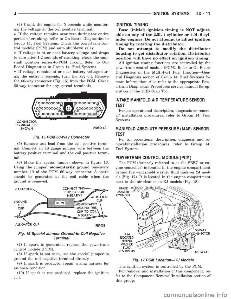
the 60-way connector (Fig. 15) from the PCM. Check
60-way connector for any spread terminals.
(5) Remove test lead from the coil positive termi-
nal. Connect an 18 gauge jumper wire between the
battery positive terminal and the coil positive termi-
nal.
(6) Make the special jumper shown in figure 16.
Using the jumper,momentarilyground pin/cavity
number 19 of the PCM 60-way connector. A spark
should be generated at the coil cable when the
ground is removed.
(7) If spark is generated, replace the powertrain
control module (PCM).
(8) If spark is not seen, use the special jumper to
ground the coil negative terminal directly.
(9) If spark is produced, repair wiring harness for
an open condition.
(10) If spark is not produced, replace the ignition
coil.IGNITION TIMING
Base (initial) ignition timing is NOT adjust-
able on any of the 2.5L 4-cylinder or 4.0L 6-cyl-
inder engines. Do not attempt to adjust ignition
timing by rotating the distributor.
Do not attempt to modify the distributor
housing to get distributor rotation. Distributor
position will have no effect on ignition timing.
All ignition timing functions are controlled by the
powertrain control module (PCM). Refer to On-Board
Diagnostics in the Multi-Port Fuel InjectionÐGen-
eral Diagnosis section of Group 14, Fuel Systems for
more information. Also refer to the appropriate Pow-
ertrain Diagnostics Procedures service manual for op-
eration of the DRB Scan Tool.
INTAKE MANIFOLD AIR TEMPERATURE SENSOR
TEST
For an operational description, diagnosis or remov-
al/ installation procedures, refer to Group 14, Fuel
Systems.
MANIFOLD ABSOLUTE PRESSURE (MAP) SENSOR
TEST
For an operational description, diagnosis and re-
moval/installation procedures, refer to Group 14,
Fuel System.
POWERTRAIN CONTROL MODULE (PCM)
The PCM (formerly referred to as the SBEC or en-
gine controller) is located in the engine compartment
behind the windshield washer fluid tank on YJ mod-
els (Fig. 17). It is located in the engine compartment
next to the air cleaner on XJ models (Fig. 18).
The ignition system is controlled by the PCM.
For removal and installation of this component, re-
fer to the Component Removal/Installation section of
this group.
Fig. 15 PCM 60-Way Connector
Fig. 16 Special Jumper Ground-to-Coil Negative
Terminal
Fig. 17 PCM LocationÐYJ Models
JIGNITION SYSTEMS 8D - 11
Page 375 of 2198
INDICATOR LAMPS
If an individual indicator lamp is inoperative, see
the diagnostic procedure under the heading for that
lamp. If more than one indicator lamp or a combina-
tion of lamps and gauges in the main cluster or the
gauge package cluster is inoperative, see Gauges in
this section for diagnosis.
ANTI-LOCK BRAKE SYSTEM LAMP
The diagnosis found here addresses an inoperative
lamp condition. If the ABS lamp stays on with the ig-
nition switch in the ON position, or comes on and
stays on while driving, refer to Group 5 - Brakes for
diagnosis. If no ABS problem is found, the following
procedure will help locate a short or open in the ABS
lamp circuit.
(1) Disconnect battery negative cable. Remove left
instrument cluster bezel and main cluster assembly.
Disconnect ABS control module connector.
(2) Install a jumper wire between cavity 6 of clus-
ter connector and a good ground. Connect battery
negative cable. Turn ignition switch to ON. Lamp
should light. If OK, remove jumper wire and go to
next step. If not OK, replace bulb.
(3) Turn ignition switch to OFF. Disconnect battery
negative cable and unplug cluster connector. Check
for continuity between cavity 6 of cluster connector
and a good ground. There should be no continuity. If
OK, go to next step. If not OK, repair short circuit as
required.
(4) Check continuity between cavity 6 of cluster
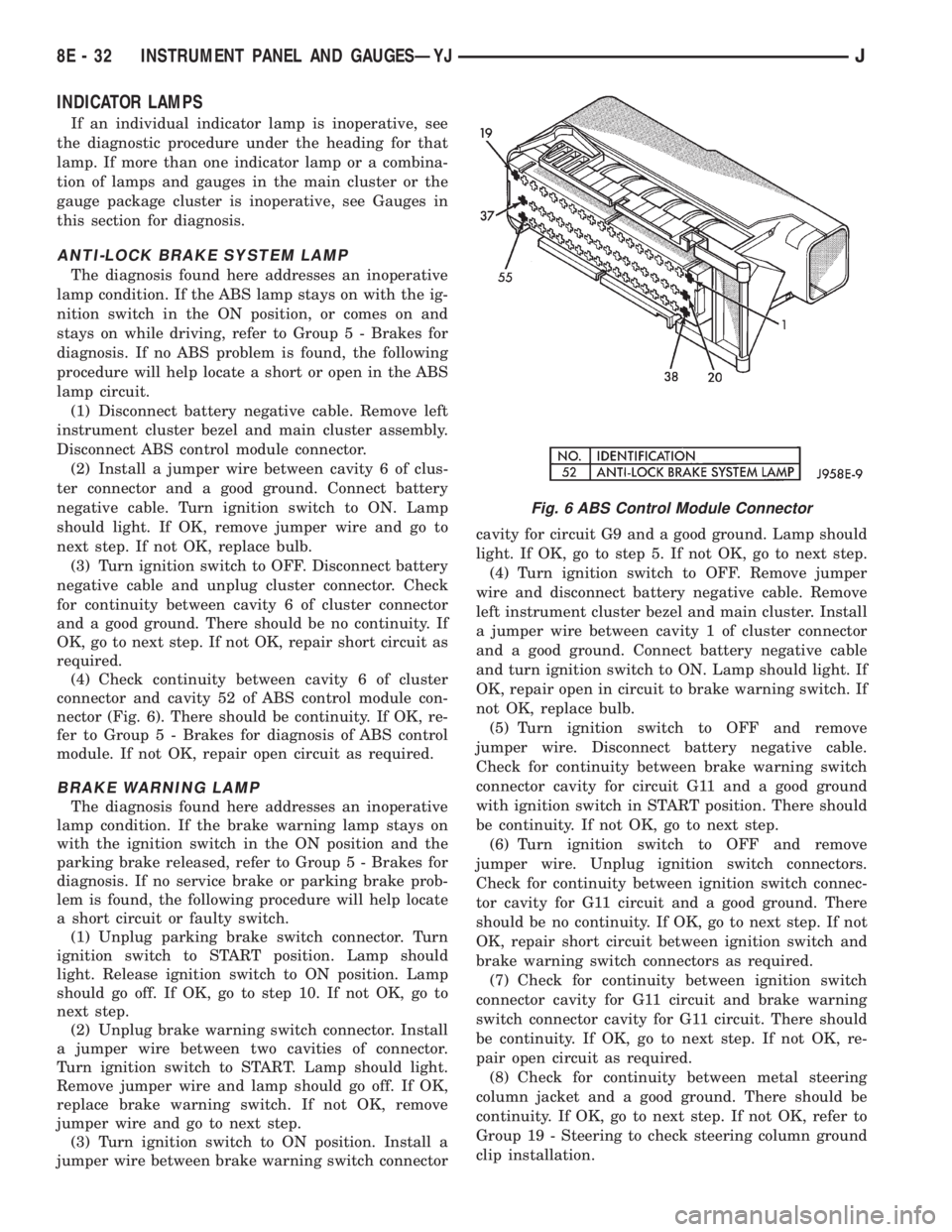
connector and cavity 52 of ABS control module con-
nector (Fig. 6). There should be continuity. If OK, re-
fer to Group 5 - Brakes for diagnosis of ABS control
module. If not OK, repair open circuit as required.
BRAKE WARNING LAMP
The diagnosis found here addresses an inoperative
lamp condition. If the brake warning lamp stays on
with the ignition switch in the ON position and the
parking brake released, refer to Group 5 - Brakes for
diagnosis. If no service brake or parking brake prob-
lem is found, the following procedure will help locate
a short circuit or faulty switch.
(1) Unplug parking brake switch connector. Turn
ignition switch to START position. Lamp should
light. Release ignition switch to ON position. Lamp
should go off. If OK, go to step 10. If not OK, go to
next step.
(2) Unplug brake warning switch connector. Install
a jumper wire between two cavities of connector.
Turn ignition switch to START. Lamp should light.
Remove jumper wire and lamp should go off. If OK,
replace brake warning switch. If not OK, remove
jumper wire and go to next step.
(3) Turn ignition switch to ON position. Install a
jumper wire between brake warning switch connectorcavity for circuit G9 and a good ground. Lamp should
light. If OK, go to step 5. If not OK, go to next step.
(4) Turn ignition switch to OFF. Remove jumper
wire and disconnect battery negative cable. Remove
left instrument cluster bezel and main cluster. Install
a jumper wire between cavity 1 of cluster connector
and a good ground. Connect battery negative cable
and turn ignition switch to ON. Lamp should light. If
OK, repair open in circuit to brake warning switch. If
not OK, replace bulb.
(5) Turn ignition switch to OFF and remove
jumper wire. Disconnect battery negative cable.
Check for continuity between brake warning switch
connector cavity for circuit G11 and a good ground
with ignition switch in START position. There should
be continuity. If not OK, go to next step.
(6) Turn ignition switch to OFF and remove
jumper wire. Unplug ignition switch connectors.
Check for continuity between ignition switch connec-
tor cavity for G11 circuit and a good ground. There
should be no continuity. If OK, go to next step. If not
OK, repair short circuit between ignition switch and
brake warning switch connectors as required.
(7) Check for continuity between ignition switch
connector cavity for G11 circuit and brake warning
switch connector cavity for G11 circuit. There should
be continuity. If OK, go to next step. If not OK, re-
pair open circuit as required.
(8) Check for continuity between metal steering
column jacket and a good ground. There should be
continuity. If OK, go to next step. If not OK, refer to
Group 19 - Steering to check steering column ground
clip installation.
Fig. 6 ABS Control Module Connector
8E - 32 INSTRUMENT PANEL AND GAUGESÐYJJ
Page 457 of 2198
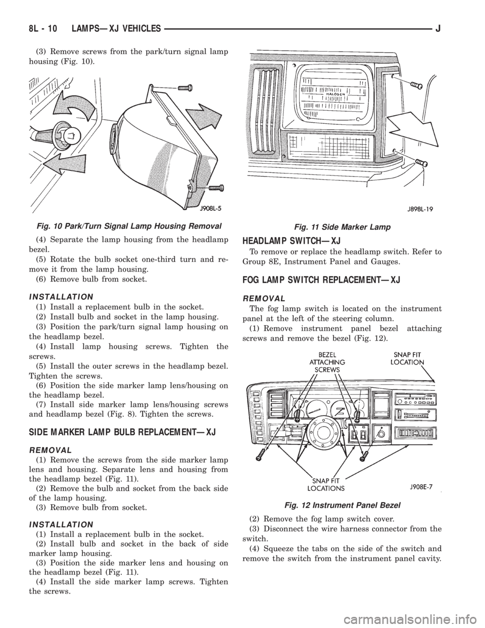
(3) Remove screws from the park/turn signal lamp
housing (Fig. 10).
(4) Separate the lamp housing from the headlamp
bezel.
(5) Rotate the bulb socket one-third turn and re-
move it from the lamp housing.
(6) Remove bulb from socket.
INSTALLATION
(1) Install a replacement bulb in the socket.
(2) Install bulb and socket in the lamp housing.
(3) Position the park/turn signal lamp housing on
the headlamp bezel.
(4) Install lamp housing screws. Tighten the
screws.
(5) Install the outer screws in the headlamp bezel.
Tighten the screws.
(6) Position the side marker lamp lens/housing on
the headlamp bezel.
(7) Install side marker lamp lens/housing screws
and headlamp bezel (Fig. 8). Tighten the screws.
SIDE MARKER LAMP BULB REPLACEMENTÐXJ
REMOVAL
(1) Remove the screws from the side marker lamp
lens and housing. Separate lens and housing from
the headlamp bezel (Fig. 11).
(2) Remove the bulb and socket from the back side
of the lamp housing.
(3) Remove bulb from socket.
INSTALLATION
(1) Install a replacement bulb in the socket.
(2) Install bulb and socket in the back of side
marker lamp housing.
(3) Position the side marker lens and housing on
the headlamp bezel (Fig. 11).
(4) Install the side marker lamp screws. Tighten
the screws.
HEADLAMP SWITCHÐXJ
To remove or replace the headlamp switch. Refer to
Group 8E, Instrument Panel and Gauges.
FOG LAMP SWITCH REPLACEMENTÐXJ
REMOVAL
The fog lamp switch is located on the instrument
panel at the left of the steering column.
(1) Remove instrument panel bezel attaching
screws and remove the bezel (Fig. 12).
(2) Remove the fog lamp switch cover.
(3) Disconnect the wire harness connector from the
switch.
(4) Squeeze the tabs on the side of the switch and
remove the switch from the instrument panel cavity.
Fig. 10 Park/Turn Signal Lamp Housing RemovalFig. 11 Side Marker Lamp
Fig. 12 Instrument Panel Bezel
8L - 10 LAMPSÐXJ VEHICLESJ
Page 473 of 2198
HEADLAMP SWITCHÐYJ
To remove or replace the headlamp switch, refer to
Group 8E, Instrument Panel and Gauges.
FOG LAMP SWITCH REPLACEMENTÐYJ
REMOVAL
The fog lamp switch is located on the instrument
panel at the right of the steering column. The fog
lamp circuit relay is located below the left headlamp.
(1) Disconnect the battery negative cable.
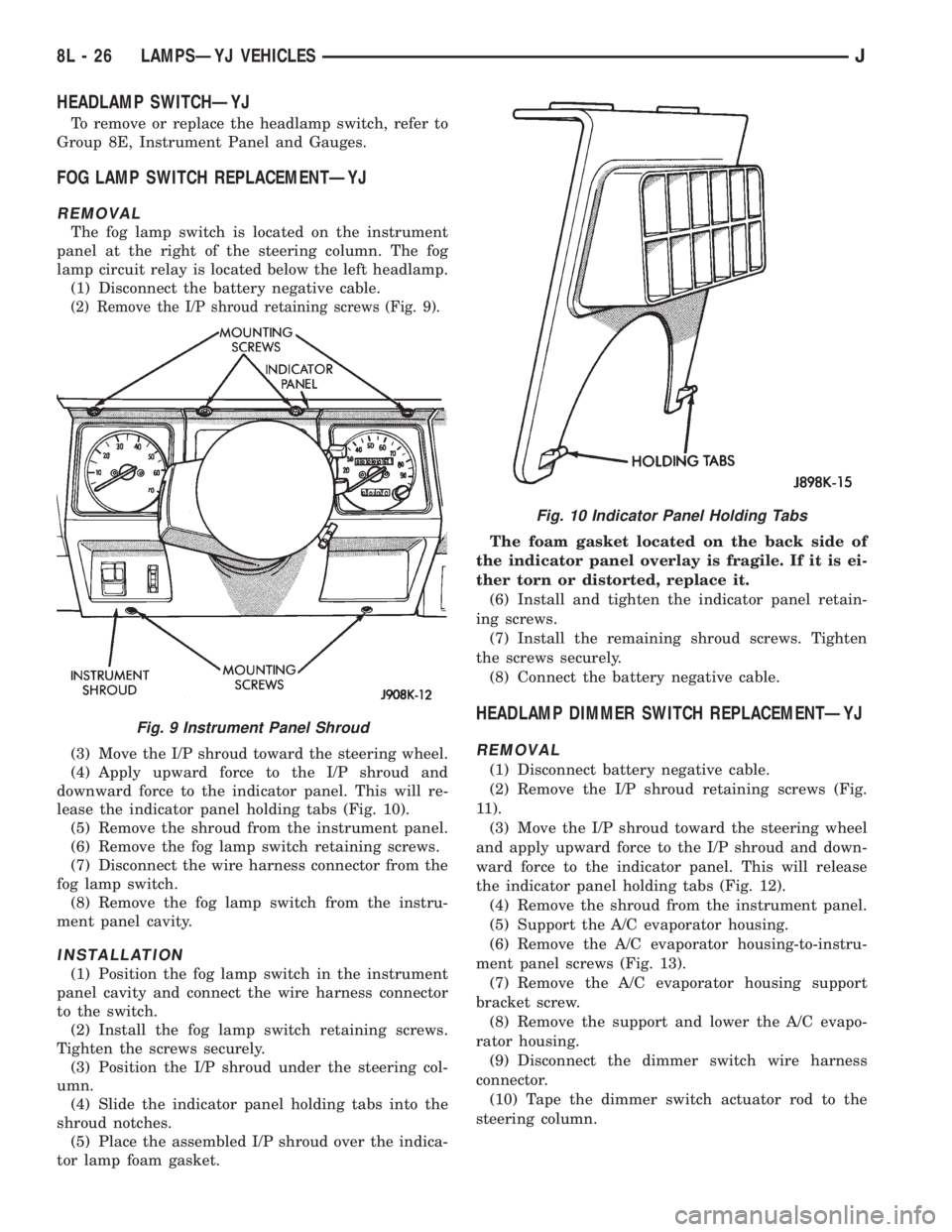
(2) Remove the I/P shroud retaining screws (Fig. 9).
(3) Move the I/P shroud toward the steering wheel.
(4) Apply upward force to the I/P shroud and
downward force to the indicator panel. This will re-
lease the indicator panel holding tabs (Fig. 10).
(5) Remove the shroud from the instrument panel.
(6) Remove the fog lamp switch retaining screws.
(7) Disconnect the wire harness connector from the
fog lamp switch.
(8) Remove the fog lamp switch from the instru-
ment panel cavity.
INSTALLATION
(1) Position the fog lamp switch in the instrument
panel cavity and connect the wire harness connector
to the switch.
(2) Install the fog lamp switch retaining screws.
Tighten the screws securely.
(3) Position the I/P shroud under the steering col-
umn.
(4) Slide the indicator panel holding tabs into the
shroud notches.
(5) Place the assembled I/P shroud over the indica-
tor lamp foam gasket.The foam gasket located on the back side of
the indicator panel overlay is fragile. If it is ei-
ther torn or distorted, replace it.
(6) Install and tighten the indicator panel retain-
ing screws.
(7) Install the remaining shroud screws. Tighten
the screws securely.
(8) Connect the battery negative cable.
HEADLAMP DIMMER SWITCH REPLACEMENTÐYJ
REMOVAL
(1) Disconnect battery negative cable.
(2) Remove the I/P shroud retaining screws (Fig.
11).
(3) Move the I/P shroud toward the steering wheel
and apply upward force to the I/P shroud and down-
ward force to the indicator panel. This will release
the indicator panel holding tabs (Fig. 12).
(4) Remove the shroud from the instrument panel.
(5) Support the A/C evaporator housing.
(6) Remove the A/C evaporator housing-to-instru-
ment panel screws (Fig. 13).
(7) Remove the A/C evaporator housing support
bracket screw.
(8) Remove the support and lower the A/C evapo-
rator housing.
(9) Disconnect the dimmer switch wire harness
connector.
(10) Tape the dimmer switch actuator rod to the
steering column.
Fig. 9 Instrument Panel Shroud
Fig. 10 Indicator Panel Holding Tabs
8L - 26 LAMPSÐYJ VEHICLESJ
Page 487 of 2198
(9) Allow epoxy to cure 24 hours at room tempera-
ture or use heat gun with a 260É-371ÉC (500É-700ÉF)
range for 15 minutes. Hold gun approximately
254mm (10 inches) from repaired area.
(10) After conductive epoxy is properly cured re-
move wedge or clamp from terminal or pigtail and
check operation of rear window defogger. Do not at-
tach connectors until curing is complete.
DEFOGGER SWITCH REMOVE/INSTALL
XJ MODELS
(1) Remove the instrument cluster bezel. Refer to
Group 8E - Instrument Panel and Gauges for proce-
dure.
(2) Remove the switch housing panel.
(3) Unplug the switch connector. Slightly depress
the switch mounting tabs and remove the switch.
(4) Reverse removal procedures to install.
YJ MODELS
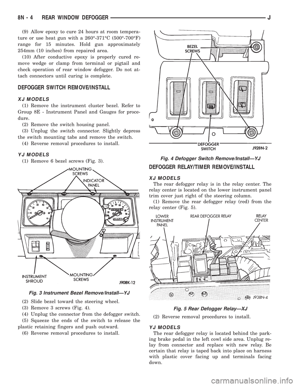
(1) Remove 6 bezel screws (Fig. 3).
(2) Slide bezel toward the steering wheel.
(3) Remove 3 screws (Fig. 4).
(4) Unplug the connector from the defogger switch.
(5) Squeeze the ends of the switch to release the
plastic retaining fingers and push outward.
(6) Reverse removal procedures to install.
DEFOGGER RELAY/TIMER REMOVE/INSTALL
XJ MODELS
The rear defogger relay is in the relay center. The
relay center is located on the lower instrument panel
trim cover just right of the steering column.
(1) Remove the rear defogger relay (red) from the
relay center (Fig. 5).
(2) Reverse removal procedures to install.
YJ MODELS
The rear defogger relay is located behind the park-
ing brake pedal in the left cowl side area. Unplug re-
lay from connector and replace with new relay. Be
certain that relay is taped back into place on harness
with plastic cover facing up and terminals facing
down.
Fig. 3 Instrument Bezel Remove/InstallÐYJ
Fig. 4 Defogger Switch Remove/InstallÐYJ
Fig. 5 Rear Defogger RelayÐXJ
8N - 4 REAR WINDOW DEFOGGERJ
Page 1130 of 2198
OIL PUMP
The positive-displacement gear-type oil pump is
driven by the distributor shaft, which is driven by a
gear on the camshaft. Oil is siphoned into the pump
through an inlet tube and strainer assembly that is
pressed into the pump body.
The pump incorporates a nonadjustable pressure
relief valve to limit maximum pressure to 517 kPa
(75 psi). In the relief position, the valve permits oil to
bypass through a passage in the pump body to the
inlet side of the pump.
Oil pump removal or replacement will not affect
the distributor timing because the distributor drive
gear remains in mesh with the camshaft gear.
REMOVAL
(1) Drain the engine oil.
(2) Remove the oil pan.
(3) Remove the pump-to-cylinder block attaching
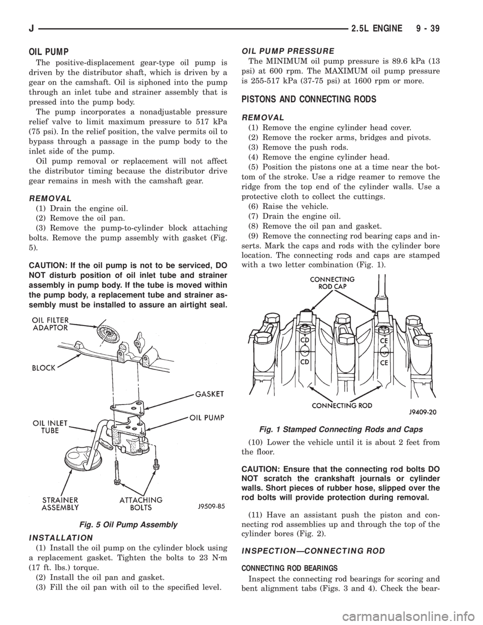
bolts. Remove the pump assembly with gasket (Fig.
5).
CAUTION: If the oil pump is not to be serviced, DO
NOT disturb position of oil inlet tube and strainer
assembly in pump body. If the tube is moved within
the pump body, a replacement tube and strainer as-
sembly must be installed to assure an airtight seal.
INSTALLATION
(1) Install the oil pump on the cylinder block using
a replacement gasket. Tighten the bolts to 23 Nzm
(17 ft. lbs.) torque.
(2) Install the oil pan and gasket.
(3) Fill the oil pan with oil to the specified level.
OIL PUMP PRESSURE
The MINIMUM oil pump pressure is 89.6 kPa (13
psi) at 600 rpm. The MAXIMUM oil pump pressure
is 255-517 kPa (37-75 psi) at 1600 rpm or more.
PISTONS AND CONNECTING RODS
REMOVAL
(1) Remove the engine cylinder head cover.
(2) Remove the rocker arms, bridges and pivots.
(3) Remove the push rods.
(4) Remove the engine cylinder head.
(5) Position the pistons one at a time near the bot-
tom of the stroke. Use a ridge reamer to remove the
ridge from the top end of the cylinder walls. Use a
protective cloth to collect the cuttings.
(6) Raise the vehicle.
(7) Drain the engine oil.
(8) Remove the oil pan and gasket.
(9) Remove the connecting rod bearing caps and in-
serts. Mark the caps and rods with the cylinder bore
location. The connecting rods and caps are stamped
with a two letter combination (Fig. 1).
(10) Lower the vehicle until it is about 2 feet from
the floor.
CAUTION: Ensure that the connecting rod bolts DO
NOT scratch the crankshaft journals or cylinder
walls. Short pieces of rubber hose, slipped over the
rod bolts will provide protection during removal.
(11) Have an assistant push the piston and con-
necting rod assemblies up and through the top of the
cylinder bores (Fig. 2).
INSPECTIONÐCONNECTING ROD
CONNECTING ROD BEARINGS
Inspect the connecting rod bearings for scoring and
bent alignment tabs (Figs. 3 and 4). Check the bear-
Fig. 5 Oil Pump Assembly
Fig. 1 Stamped Connecting Rods and Caps
J2.5L ENGINE 9 - 39
Page 1136 of 2198
CAUTION: Verify that the oil squirt holes in the rods
face the camshaft and that the arrows on the pis-
tons face the front of the engine.
(7) Install the oil pan and gaskets as outlined in
the installation procedure.
(8) Lower the vehicle.
(9) Install the engine cylinder head, push rods,
rocker arms, bridges, pivots and engine cylinder head
cover.
(10) Fill the crankcase with engine oil.
CRANKSHAFT MAIN BEARINGS
REMOVAL
(1) Disconnect negative cable from battery.
(2) Remove the spark plugs.
(3) Raise the vehicle.
(4) Remove the oil pan and oil pump.
(5) Remove only one main bearing cap and lower
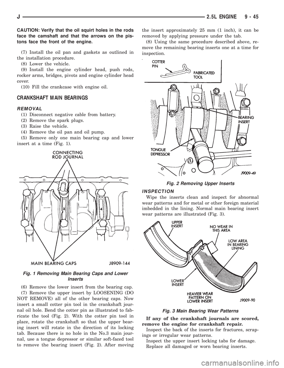
insert at a time (Fig. 1).
(6) Remove the lower insert from the bearing cap.
(7) Remove the upper insert by LOOSENING (DO
NOT REMOVE) all of the other bearing caps. Now
insert a small cotter pin tool in the crankshaft jour-
nal oil hole. Bend the cotter pin as illustrated to fab-
ricate the tool (Fig. 2). With the cotter pin tool in
place, rotate the crankshaft so that the upper bear-
ing insert will rotate in the direction of its locking
tab. Because there is no hole in the No.3 main jour-
nal, use a tongue depressor or similar soft-faced tool
to remove the bearing insert (Fig. 2). After movingthe insert approximately 25 mm (1 inch), it can be
removed by applying pressure under the tab.
(8) Using the same procedure described above, re-
move the remaining bearing inserts one at a time for
inspection.
INSPECTION
Wipe the inserts clean and inspect for abnormal
wear patterns and for metal or other foreign material
imbedded in the lining. Normal main bearing insert
wear patterns are illustrated (Fig. 3).
If any of the crankshaft journals are scored,
remove the engine for crankshaft repair.
Inspect the back of the inserts for fractures, scrap-
ings or irregular wear patterns.
Inspect the upper insert locking tabs for damage.
Replace all damaged or worn bearing inserts.
Fig. 1 Removing Main Bearing Caps and Lower
Inserts
Fig. 2 Removing Upper Inserts
Fig. 3 Main Bearing Wear Patterns
J2.5L ENGINE 9 - 45
Page 1172 of 2198
OIL PUMP
A gear-type oil pump is mounted at the underside
of the cylinder block opposite the No.4 main bearing.
The pump incorporates a nonadjustable pressure
relief valve to limit maximum pressure to 517 kPa
(75 psi). In the relief position, the valve permits oil to
bypass through a passage in the pump body to the
inlet side of the pump.
Oil pump removal or replacement will not affect
the distributor timing because the distributor drive
gear remains in mesh with the camshaft gear.
REMOVAL
(1) Drain the engine oil.
(2) Remove the oil pan.
(3) Remove the pump-to-cylinder block attaching
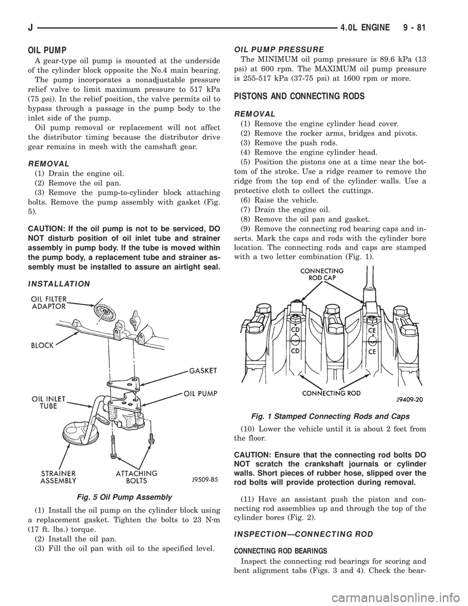
bolts. Remove the pump assembly with gasket (Fig.
5).
CAUTION: If the oil pump is not to be serviced, DO
NOT disturb position of oil inlet tube and strainer
assembly in pump body. If the tube is moved within
the pump body, a replacement tube and strainer as-
sembly must be installed to assure an airtight seal.
INSTALLATION
(1) Install the oil pump on the cylinder block using
a replacement gasket. Tighten the bolts to 23 Nzm
(17 ft. lbs.) torque.
(2) Install the oil pan.
(3) Fill the oil pan with oil to the specified level.
OIL PUMP PRESSURE
The MINIMUM oil pump pressure is 89.6 kPa (13
psi) at 600 rpm. The MAXIMUM oil pump pressure
is 255-517 kPa (37-75 psi) at 1600 rpm or more.
PISTONS AND CONNECTING RODS
REMOVAL
(1) Remove the engine cylinder head cover.
(2) Remove the rocker arms, bridges and pivots.
(3) Remove the push rods.
(4) Remove the engine cylinder head.
(5) Position the pistons one at a time near the bot-
tom of the stroke. Use a ridge reamer to remove the
ridge from the top end of the cylinder walls. Use a
protective cloth to collect the cuttings.
(6) Raise the vehicle.
(7) Drain the engine oil.
(8) Remove the oil pan and gasket.
(9) Remove the connecting rod bearing caps and in-
serts. Mark the caps and rods with the cylinder bore
location. The connecting rods and caps are stamped
with a two letter combination (Fig. 1).
(10) Lower the vehicle until it is about 2 feet from
the floor.
CAUTION: Ensure that the connecting rod bolts DO
NOT scratch the crankshaft journals or cylinder
walls. Short pieces of rubber hose, slipped over the
rod bolts will provide protection during removal.
(11) Have an assistant push the piston and con-
necting rod assemblies up and through the top of the
cylinder bores (Fig. 2).
INSPECTIONÐCONNECTING ROD
CONNECTING ROD BEARINGS
Inspect the connecting rod bearings for scoring and
bent alignment tabs (Figs. 3 and 4). Check the bear-
Fig. 5 Oil Pump Assembly
Fig. 1 Stamped Connecting Rods and Caps
J4.0L ENGINE 9 - 81