1995 JEEP CHEROKEE abs ring replace
[x] Cancel search: abs ring replacePage 1513 of 2198
Replace the clutch discs if warped, worn, scored,
burned or charred, or if the facing is flaking off. Re-
place the steel plates if heavily scored, warped, or
broken. Be sure the driving lugs on the plates are in
good condition. The lugs must not be bent, cracked or
damaged in any way.
Replace the clutch spring and spring retainer if ei-
ther is distorted, warped or broken.
Check the lug grooves in the clutch retainer. The
steel plates should slide freely in the slots. Replace
the retainer if the grooves are worn or damaged.
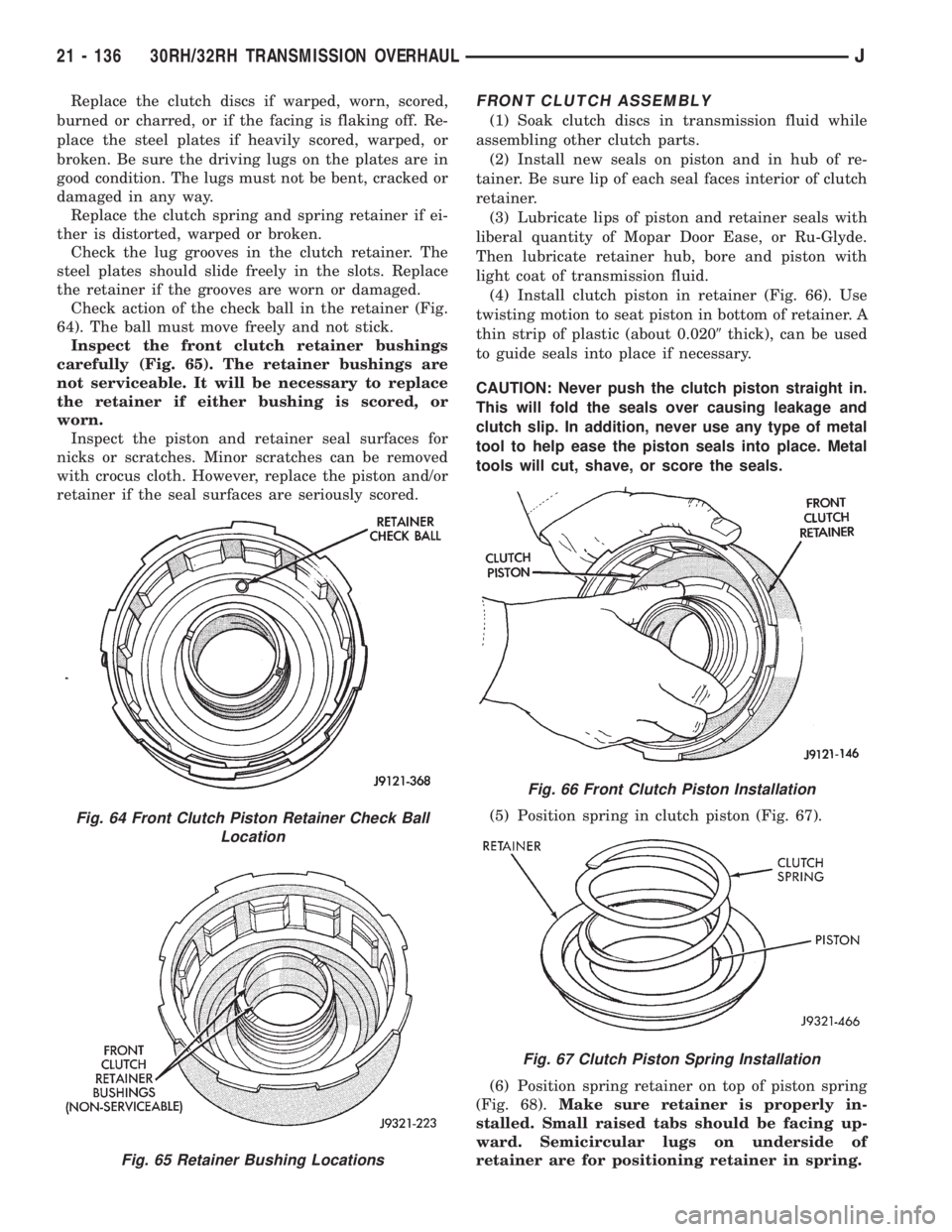
Check action of the check ball in the retainer (Fig.
64). The ball must move freely and not stick.
Inspect the front clutch retainer bushings
carefully (Fig. 65). The retainer bushings are
not serviceable. It will be necessary to replace
the retainer if either bushing is scored, or
worn.
Inspect the piston and retainer seal surfaces for
nicks or scratches. Minor scratches can be removed
with crocus cloth. However, replace the piston and/or
retainer if the seal surfaces are seriously scored.FRONT CLUTCH ASSEMBLY
(1) Soak clutch discs in transmission fluid while
assembling other clutch parts.
(2) Install new seals on piston and in hub of re-
tainer. Be sure lip of each seal faces interior of clutch
retainer.
(3) Lubricate lips of piston and retainer seals with
liberal quantity of Mopar Door Ease, or Ru-Glyde.
Then lubricate retainer hub, bore and piston with
light coat of transmission fluid.
(4) Install clutch piston in retainer (Fig. 66). Use
twisting motion to seat piston in bottom of retainer. A
thin strip of plastic (about 0.0209thick), can be used
to guide seals into place if necessary.
CAUTION: Never push the clutch piston straight in.
This will fold the seals over causing leakage and
clutch slip. In addition, never use any type of metal
tool to help ease the piston seals into place. Metal
tools will cut, shave, or score the seals.
(5) Position spring in clutch piston (Fig. 67).
(6) Position spring retainer on top of piston spring
(Fig. 68).Make sure retainer is properly in-
stalled. Small raised tabs should be facing up-
ward. Semicircular lugs on underside of
retainer are for positioning retainer in spring.
Fig. 64 Front Clutch Piston Retainer Check Ball
Location
Fig. 65 Retainer Bushing Locations
Fig. 66 Front Clutch Piston Installation
Fig. 67 Clutch Piston Spring Installation
21 - 136 30RH/32RH TRANSMISSION OVERHAULJ
Page 1519 of 2198
planetary. All the washers have four locating tabs on
them. These tabs fit in the holes or slots provided in
each planetary gear.
Inspect the output shaft carefully. Pay particular
attention to the machined bushing/bearing surfaces
on the shaft and the governor valve shaft bore at the
shaft rear.
Replace the output shaft if the machined surfaces
are scored, pitted, or damaged in any way. Also re-
place the shaft if the splines are damaged, or exhib-
it cracks at any location (especially at the governor
valve shaft bore).
The annulus gears can be removed from their sup-
ports if necessary. Just remove the snap rings and sep-
arate the two parts when replacement is necessary. In
addition, the annulus gear bushings can be replaced if
severely worn, or scored. However it is not necessary to
replace the bushings if they only exhibit normal wear.
Check bushing fit on the output shaft to be sure.
ASSEMBLING PLANETARY GEARTRAIN
(1) Lubricate output shaft and planetary components
with transmission fluid. Use petroleum jelly to lubricate
and hold thrust washers and plates in position.
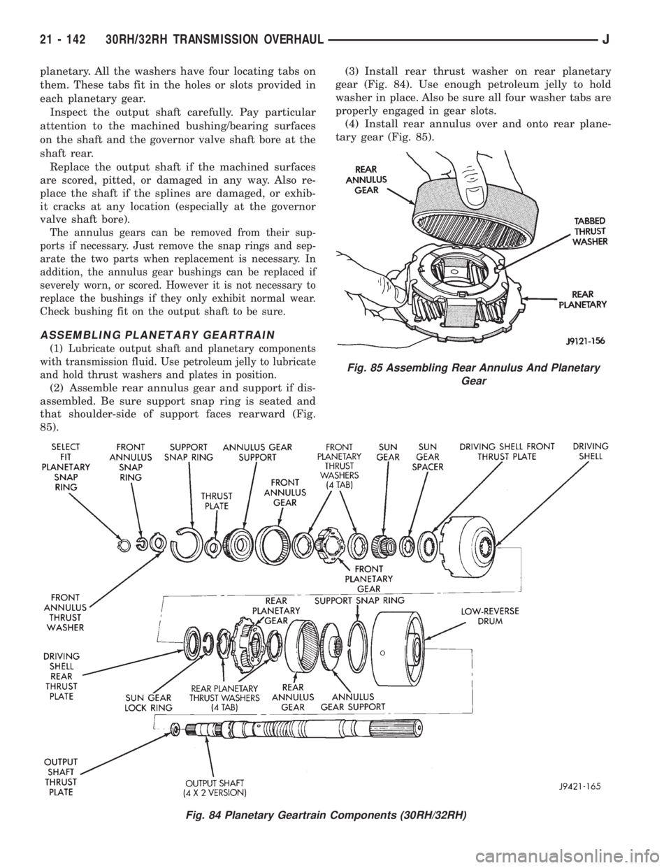
(2) Assemble rear annulus gear and support if dis-
assembled. Be sure support snap ring is seated and
that shoulder-side of support faces rearward (Fig.
85).(3) Install rear thrust washer on rear planetary
gear (Fig. 84). Use enough petroleum jelly to hold
washer in place. Also be sure all four washer tabs are
properly engaged in gear slots.
(4) Install rear annulus over and onto rear plane-
tary gear (Fig. 85).
Fig. 84 Planetary Geartrain Components (30RH/32RH)
Fig. 85 Assembling Rear Annulus And Planetary
Gear
21 - 142 30RH/32RH TRANSMISSION OVERHAULJ
Page 1560 of 2198
(6) Let engine run at normal curb idle speed, apply
service brakes. Then shift transmission through all
gear ranges and back to PARK (leave engine run-
ning).
(7) Remove dipstick and check fluid level. Add only
enough fluid to bring level to Full mark on dipstick.
Do not overfill.If too much fluid is added, excess
amount can be removed with suction gun and
plastic tubing. Tubing only has to be long
enough to extend into oil pan.
(8) When fluid level is correct, shut engine off, re-
lease park brake, remove funnel, and reseat dipstick
in fill tube.
TRANSMISSION CONTROL MODULE (TCM)
SERVICE
Use the DRB scan tool to diagnose transmission
control module function whenever a fault is sus-
pected. Replace the module only when the scan tool
indicates the module is actually faulty.
TRANSMISSION CONTROL MODULE
REPLACEMENT
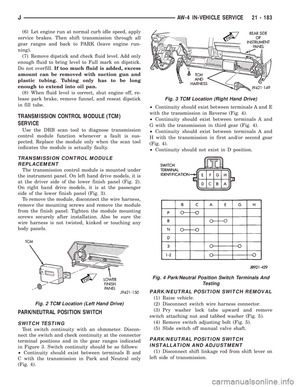
The transmission control module is mounted under
the instrument panel. On left hand drive models, it is
at the driver side of the lower finish panel (Fig. 2).
On right hand drive models, it is at the passenger
side of the lower finish panel (Fig. 3).
To remove the module, disconnect the wire harness,
remove the mounting screws and remove the module
from the finish panel. Tighten the module mounting
screws securely after installation. Also be sure the
wire harness is not twisted, kinked or touching any
body panels.
PARK/NEUTRAL POSITION SWITCH
SWITCH TESTING
Test switch continuity with an ohmmeter. Discon-
nect the switch and check continuity at the connector
terminal positions and in the gear ranges indicated
in Figure 3. Switch continuity should be as follows:
²Continuity should exist between terminals B and
C with the transmission in Park and Neutral only
(Fig. 4).²Continuity should exist between terminals A and E
with the transmission in Reverse (Fig. 4).
²Continuity should exist between terminals A and
G with the transmission in third gear (Fig. 4).
²Continuity should exist between terminals A and
H with the transmission in first and/or second gear
(Fig. 4).
²Continuity should not exist in D position.
PARK/NEUTRAL POSITION SWITCH REMOVAL
(1) Raise vehicle.
(2) Disconnect switch wire harness connector.
(3) Pry washer lock tabs upward and remove
switch attaching nut and tabbed washer (Fig. 5).
(4) Remove switch adjusting bolt (Fig. 5).
(5) Slide switch off manual valve shaft.
PARK/NEUTRAL POSITION SWITCH
INSTALLATION AND ADJUSTMENT
(1) Disconnect shift linkage rod from shift lever on
left side of transmission.
Fig. 2 TCM Location (Left Hand Drive)
Fig. 3 TCM Location (Right Hand Drive)
Fig. 4 Park/Neutral Position Switch Terminals And
Testing
JAW-4 IN-VEHICLE SERVICE 21 - 183
Page 1575 of 2198
AW-4 TRANSMISSION REMOVAL AND INSTALLATION
INDEX
page page
Oil Pump Seal Replacement................ 199
Torque Converter Stator Clutch Inspection...... 199Transmission and Torque Converter Installation . . 199
Transmission and Torque Converter Removal.... 198
TRANSMISSION AND TORQUE CONVERTER
REMOVAL
(1) Raise vehicle.
(2) Drain transmission fluid and reinstall oil pan
drain plug.
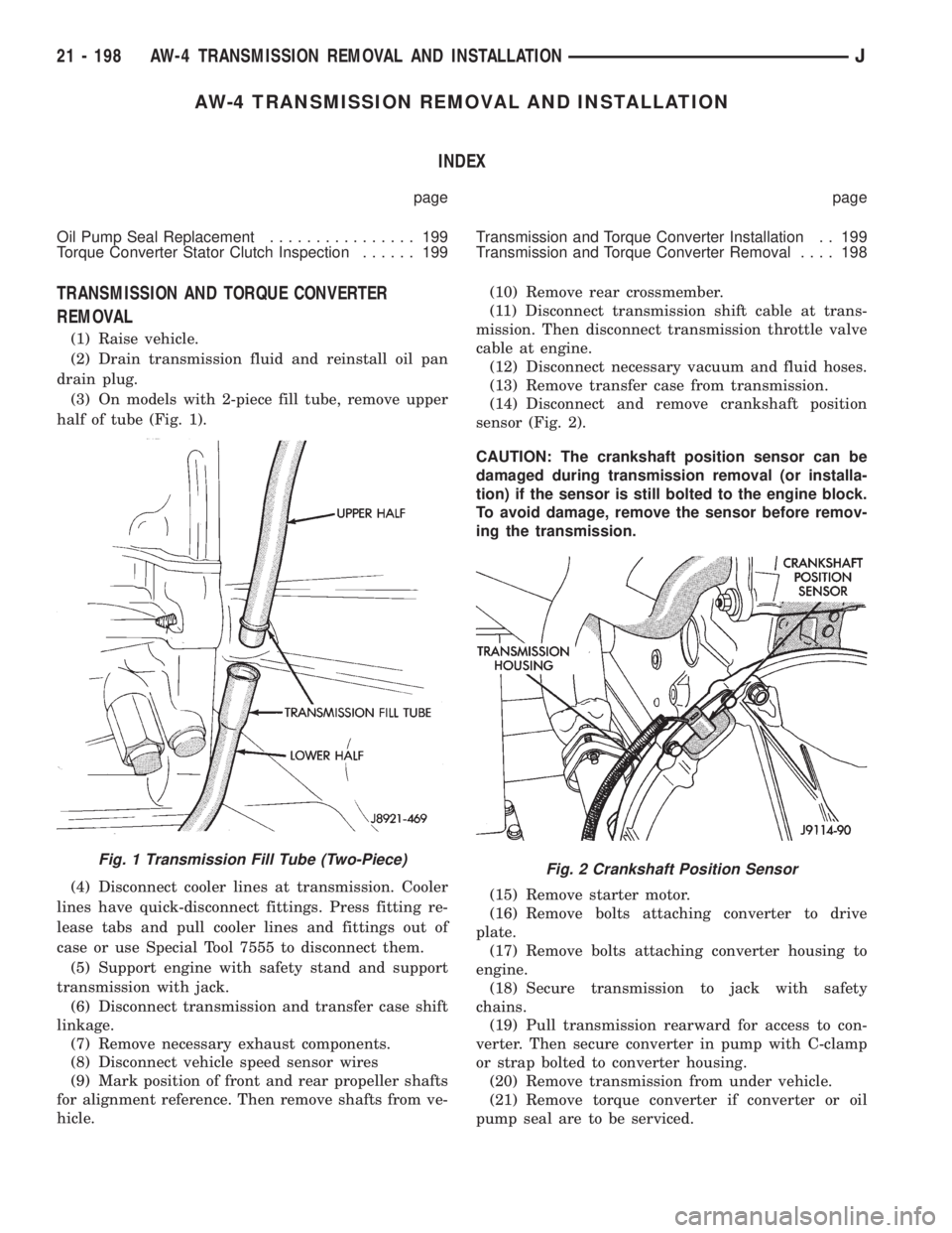
(3) On models with 2-piece fill tube, remove upper
half of tube (Fig. 1).
(4) Disconnect cooler lines at transmission. Cooler
lines have quick-disconnect fittings. Press fitting re-
lease tabs and pull cooler lines and fittings out of
case or use Special Tool 7555 to disconnect them.
(5) Support engine with safety stand and support
transmission with jack.
(6) Disconnect transmission and transfer case shift
linkage.
(7) Remove necessary exhaust components.
(8) Disconnect vehicle speed sensor wires
(9) Mark position of front and rear propeller shafts
for alignment reference. Then remove shafts from ve-
hicle.(10) Remove rear crossmember.
(11) Disconnect transmission shift cable at trans-
mission. Then disconnect transmission throttle valve
cable at engine.
(12) Disconnect necessary vacuum and fluid hoses.
(13) Remove transfer case from transmission.
(14) Disconnect and remove crankshaft position
sensor (Fig. 2).
CAUTION: The crankshaft position sensor can be
damaged during transmission removal (or installa-
tion) if the sensor is still bolted to the engine block.
To avoid damage, remove the sensor before remov-
ing the transmission.
(15) Remove starter motor.
(16) Remove bolts attaching converter to drive
plate.
(17) Remove bolts attaching converter housing to
engine.
(18) Secure transmission to jack with safety
chains.
(19) Pull transmission rearward for access to con-
verter. Then secure converter in pump with C-clamp
or strap bolted to converter housing.
(20) Remove transmission from under vehicle.
(21) Remove torque converter if converter or oil
pump seal are to be serviced.
Fig. 1 Transmission Fill Tube (Two-Piece)Fig. 2 Crankshaft Position Sensor
21 - 198 AW-4 TRANSMISSION REMOVAL AND INSTALLATIONJ
Page 1617 of 2198
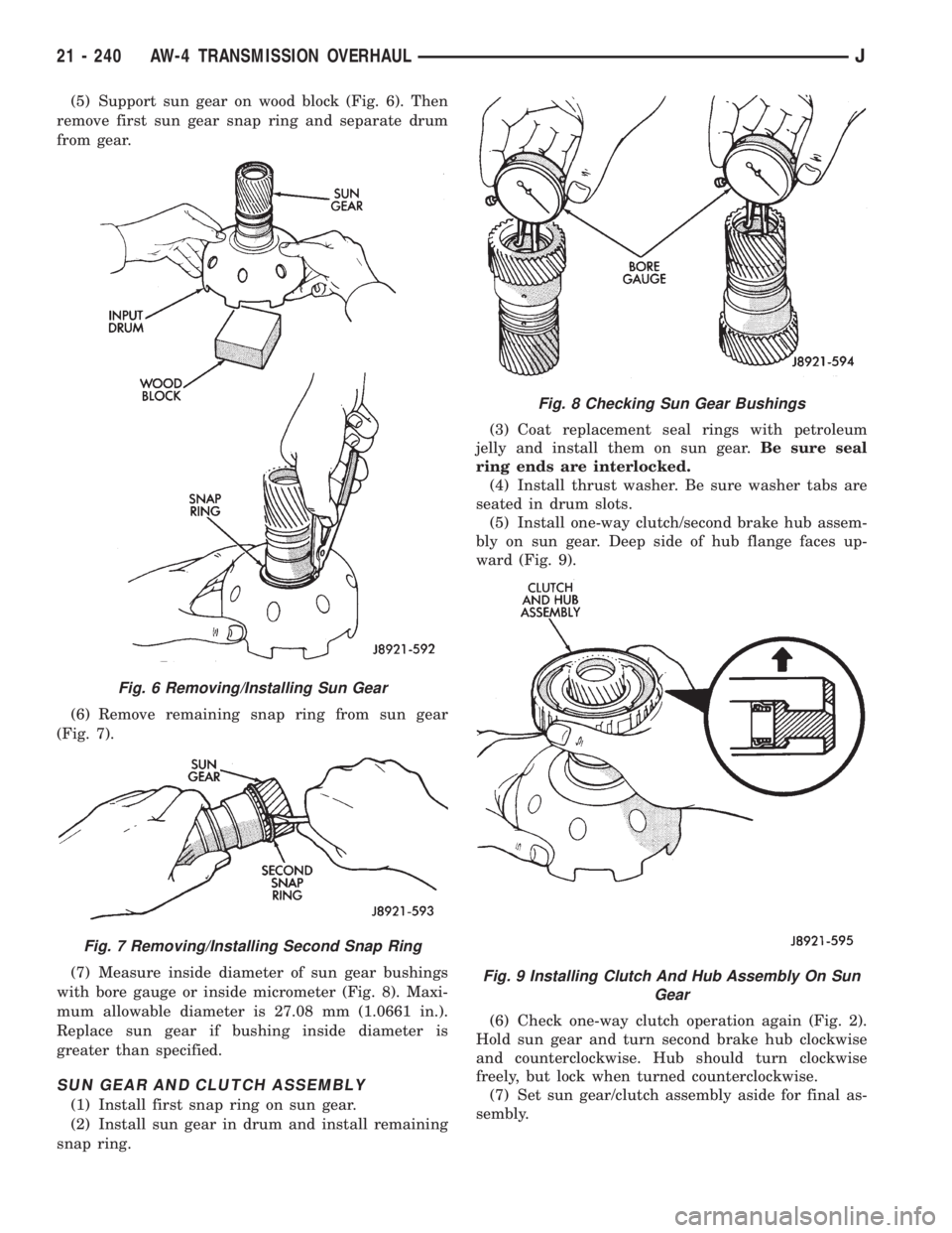
(5) Support sun gear on wood block (Fig. 6). Then
remove first sun gear snap ring and separate drum
from gear.
(6) Remove remaining snap ring from sun gear
(Fig. 7).
(7) Measure inside diameter of sun gear bushings
with bore gauge or inside micrometer (Fig. 8). Maxi-
mum allowable diameter is 27.08 mm (1.0661 in.).
Replace sun gear if bushing inside diameter is
greater than specified.
SUN GEAR AND CLUTCH ASSEMBLY
(1) Install first snap ring on sun gear.
(2) Install sun gear in drum and install remaining
snap ring.(3) Coat replacement seal rings with petroleum
jelly and install them on sun gear.Be sure seal
ring ends are interlocked.
(4) Install thrust washer. Be sure washer tabs are
seated in drum slots.
(5) Install one-way clutch/second brake hub assem-
bly on sun gear. Deep side of hub flange faces up-
ward (Fig. 9).
(6) Check one-way clutch operation again (Fig. 2).
Hold sun gear and turn second brake hub clockwise
and counterclockwise. Hub should turn clockwise
freely, but lock when turned counterclockwise.
(7) Set sun gear/clutch assembly aside for final as-
sembly.
Fig. 6 Removing/Installing Sun Gear
Fig. 7 Removing/Installing Second Snap Ring
Fig. 8 Checking Sun Gear Bushings
Fig. 9 Installing Clutch And Hub Assembly On Sun
Gear
21 - 240 AW-4 TRANSMISSION OVERHAULJ
Page 1904 of 2198
WARNINGS, CAUTIONS AND SERVICE PRECAUTIONS
WARNINGS
WARNING: THE AIR CONDITIONING SYSTEM CON-
TAINS REFRIGERANT UNDER HIGH PRESSURE.
SEVERE PERSONAL INJURY MAY RESULT FROM
IMPROPER SERVICE PROCEDURES. REPAIRS
SHOULD ONLY BE PERFORMED BY QUALIFIED
SERVICE PERSONNEL.
WARNING: AVOID BREATHING A/C REFRIGERANT
AND LUBRICANT VAPOR OR MIST. EXPOSURE MAY
IRRITATE EYES, NOSE AND/OR THROAT. WEAR
EYE PROTECTION WHEN SERVICING THE AIR
CONDITIONING REFRIGERANT SYSTEM. SERIOUS
EYE INJURY CAN RESULT FROM EYE CONTACT
WITH REFRIGERANT. IF EYE CONTACT IS MADE,
SEEK MEDICAL ATTENTION IMMEDIATELY.
WARNING: DO NOT EXPOSE REFRIGERANT TO
OPEN FLAME. POISONOUS GAS IS CREATED
WHEN REFRIGERANT IS BURNED. AN ELEC-
TRONIC TYPE LEAK DETECTOR IS RECOM-
MENDED.
WARNING: IF ACCIDENTAL SYSTEM DISCHARGE
OCCURS, VENTILATE THE WORK AREA BEFORE
RESUMING SERVICE. LARGE AMOUNTS OF RE-
FRIGERANT RELEASED IN A CLOSED WORK AREA
WILL DISPLACE THE OXYGEN AND CAUSE SUFFO-
CATION.
WARNING: THE EVAPORATION RATE OF (R-134A)
REFRIGERANT AT AVERAGE TEMPERATURE AND
ALTITUDE IS EXTREMELY HIGH. AS A RESULT,
ANYTHING THAT COMES IN CONTACT WITH THE
REFRIGERANT WILL FREEZE. ALWAYS PROTECT
SKIN OR DELICATE OBJECTS FROM DIRECT CON-
TACT WITH REFRIGERANT.
WARNING: R-134A SERVICE EQUIPMENT OR VEHI-
CLE A/C SYSTEM SHOULD NOT BE PRESSURE
TESTED OR LEAK TESTED WITH COMPRESSED
AIR. SOME MIXTURES OF AIR AND R-134A HAVE
BEEN SHOWN TO BE COMBUSTIBLE AT ELEVATED
PRESSURES. THESE MIXTURES ARE POTENTIALLY
DANGEROUS AND MAY RESULT IN FIRE OR EX-
PLOSION CAUSING INJURY OR PROPERTY DAM-
AGE.
CAUTIONS
CAUTION: Liquid refrigerant is corrosive to metal
surfaces. Follow the operating instructions supplied
with equipment being used.
CAUTION: DO NOT use R-12 equipment or parts on
the R-134a system. Damage to the system will re-
sult.
CAUTION: Never add R-12 to a system designed to
use R-134a. Damage to the system will result.
CAUTION: R-12 compressor oil can not be mixed
with the R-134a compressor oil. They ARE NOT
compatible.
CAUTION: Do not over charge refrigerant system.
This will cause excessive compressor head pres-
sure and can cause noise and system failure.
SERVICE PRECAUTIONS
Recover the refrigerant before opening any fitting
or connection. Open fittings with caution even after
the system has been discharged. Never open or
loosen a connection before recovering the refrigerant.
The A/C system must always be evacuated before
charging.
DO NOT open the refrigerant system or uncap a
replacement component until you are ready to service
the system. This will prevent contamination in the
system.
Before disconnecting a component clean the outside
of the fittings thoroughly to prevent contamination
entering the system.
Immediately after disconnecting a component from
the system, seal the open fittings with a cap or plug.
Before connecting an open fitting always install a
new seal/gasket. Coat the fitting and seal with clean
refrigerant oil before connecting.
When installing a refrigerant line avoid sharp
bends. Position the lines away from the exhaust or
any sharp edges which may chafe the line.
Tighten fittings only to the specified torque. The
aluminum fittings used in the A/C system will not
tolerate over tightening.
When disconnecting a fitting use a wrench on both
halves of the fitting. This will prevent twisting of the
refrigerant lines or tubes.
Refrigerant oil absorbs moisture from the atmo-
sphere if left uncapped. DO NOT open a container of
JHEATING AND AIR CONDITIONING 24 - 9
Page 1907 of 2198
REFRIGERANT OIL
It is important to have the correct amount of oil in
the A/C system. This will ensure proper lubrication of
the compressor. Too little oil will result in damage to
the compressor. Too much oil will reduce the cooling
capacity of the system.
The oil used in the SD7H15 compressor is a poly-
alkylene glycol synthetic oil SP-20 PAG, wax-free re-
frigerant oil. Only refrigerant oil of the same type
should be used to service the system. Do not use any
other oil. The oil container should be kept tightly
capped until it is ready for use and then capped after
use to prevent contamination. Refrigerant oil will
quickly absorb any moisture it comes in contact with.
OIL LEVEL CHECK
It will not be necessary to check oil level in the
compressor or to add oil unless there has been an oil
loss. This may be due to a rupture or leak from a
line, shaft seal, evaporator or condenser. Oil loss at a
leak point will be evident by the presence of a wet,
shiny surface around the leak.
When an A/C system is assembled at the factory,
all components (except the compressor) are refriger-
ant oil free. After the system has been charged and
operated, the oil in the compressor is dispersed
through the system. The receiver-drier, evaporator,
condenser and compressor will retain a significant
amount of oil.
Refrigerant oil must be added when a receiver-
drier, evaporator, condenser or compressor are re-
placed. When the compressor is replaced, the oil
must be drained from the replaced compressor and
measured. Drain all the oil from the new compressor.
Add back into the new compressor the amount of oil
that was drained out of the old compressor.
Add an additional 30 ml (1 fluid oz.) of com-
pressor oil to the system when a receiver-drier,
condenser or evaporator is replaced.
AIR CONDITIONING PERFORMANCE TESTS
Humidity has an important bearing on the temper-
ature of the air delivered to the vehicle's interior. It
is important to understand the effect humidity has
on the performance of the system. When humidity is
high, the evaporator has to perform a double duty. It
must lower the air temperature and the temperature
of the moisture carried in the air. Condensing the
moisture in the air transfers a great deal of heat en-
ergy into the evaporator fins and tubing. This re-
duces the amount of heat the evaporator can absorb
from the air. High humidity greatly reduces the evap-
orator's ability to lower the temperature of the air.Evaporator capacity used to reduce the amount of
moisture in the air is not wasted. Wringing some of
the moisture out of the air entering the vehicle adds
to the comfort of the passengers. However, an owner
may expect too much from their air conditioning sys-
tem on humid days. A performance test is the best
way to determine whether or not the system is per-
forming up to standard. This test also provides valu-
able clues to the possible cause of trouble.
Air temperature in test room must be 21ÉC (70ÉF)
minimum for this test.
(1) Connect a Tachometer and manifold gauge set.
(2) Set A/C controls to Max A/C, temperature lever
on full cool and blower on high.
(3) Start engine and adjust idle to 1,000 RPM with
A/C clutch engaged.
(4) Engine should be warmed up with doors, win-
dows and hood closed.
(5) Insert a thermometer in the left center A/C out-
let. Operate the A/C and engine for 5 minutes. The
A/C clutch may cycle depending on ambient temper-
atures.
(6) After 5 minutes note the discharge air temper-
ature. If the clutch cycles, take the reading before
the clutch disengages.
(7) On LHD XJ vehicles open the hood and discon-
nect vacuum line going to the heater water control
valve. Observe the valve arm for movement as the
line is disconnected. Plug the vacuum line to prevent
leakage. If it does not move repair vacuum circuit.
(8) Operate the A/C for 2 more minutes and take
the discharge air temperature reading again. On XJ
vehicles if the temperature increased by more than
2ÉC (5ÉF) check the blend air door cable for correct
operation.
(9) Compare the discharge air temperature to the
A/C Performance (Temperature and Pressure) Chart.
If the discharge air temperature is high, refer to Re-
frigerant Leak Testing and Refrigerant System Diag-
nosis Chart.
(10) Compare the compressor discharge and suc-
tion pressures to the A/C Performance (Temperature
and Pressure) Chart. If the compressor discharge or
suction pressure is not normal, check the operation of
the refrigerant system. Refer to Refrigerant System
Diagnosis Chart.
If pressures are abnormal, refer to the Pressure
and Performance Diagnosis Charts.
The following chart have been developed for quick
reference.
24 - 12 HEATING AND AIR CONDITIONINGJ
Page 1919 of 2198
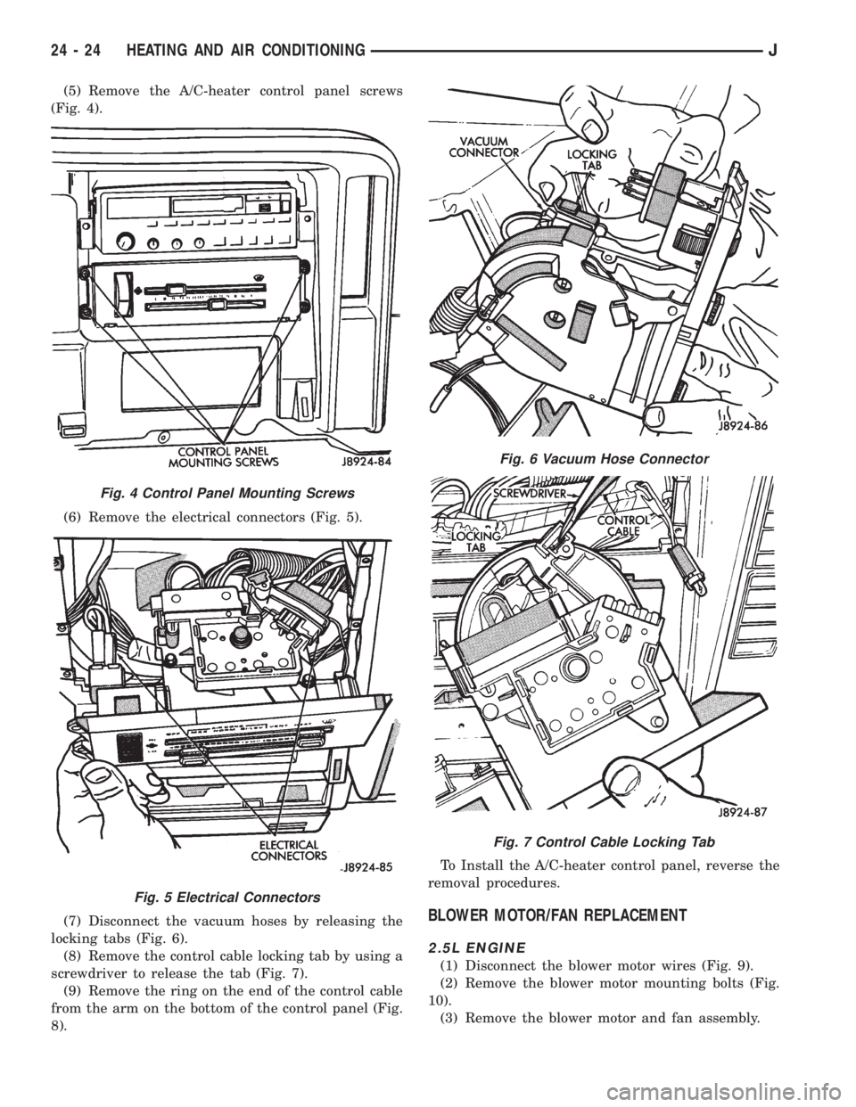
(5) Remove the A/C-heater control panel screws
(Fig. 4).
(6) Remove the electrical connectors (Fig. 5).
(7) Disconnect the vacuum hoses by releasing the
locking tabs (Fig. 6).
(8) Remove the control cable locking tab by using a
screwdriver to release the tab (Fig. 7).
(9) Remove the ring on the end of the control cable
from the arm on the bottom of the control panel (Fig.
8).To Install the A/C-heater control panel, reverse the
removal procedures.
BLOWER MOTOR/FAN REPLACEMENT
2.5L ENGINE
(1) Disconnect the blower motor wires (Fig. 9).
(2) Remove the blower motor mounting bolts (Fig.
10).
(3) Remove the blower motor and fan assembly.
Fig. 4 Control Panel Mounting Screws
Fig. 5 Electrical Connectors
Fig. 6 Vacuum Hose Connector
Fig. 7 Control Cable Locking Tab
24 - 24 HEATING AND AIR CONDITIONINGJ