1995 JEEP CHEROKEE abs ring replace
[x] Cancel search: abs ring replacePage 99 of 2198
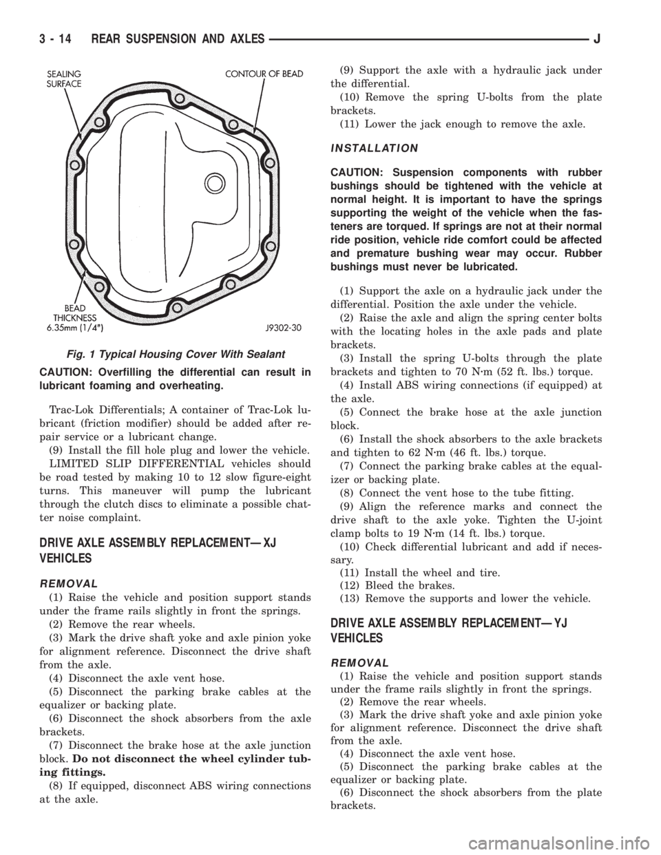
CAUTION: Overfilling the differential can result in
lubricant foaming and overheating.
Trac-Lok Differentials; A container of Trac-Lok lu-
bricant (friction modifier) should be added after re-
pair service or a lubricant change.
(9) Install the fill hole plug and lower the vehicle.
LIMITED SLIP DIFFERENTIAL vehicles should
be road tested by making 10 to 12 slow figure-eight
turns. This maneuver will pump the lubricant
through the clutch discs to eliminate a possible chat-
ter noise complaint.
DRIVE AXLE ASSEMBLY REPLACEMENTÐXJ
VEHICLES
REMOVAL
(1) Raise the vehicle and position support stands
under the frame rails slightly in front the springs.
(2) Remove the rear wheels.
(3) Mark the drive shaft yoke and axle pinion yoke
for alignment reference. Disconnect the drive shaft
from the axle.
(4) Disconnect the axle vent hose.
(5) Disconnect the parking brake cables at the
equalizer or backing plate.
(6) Disconnect the shock absorbers from the axle
brackets.
(7) Disconnect the brake hose at the axle junction
block.Do not disconnect the wheel cylinder tub-
ing fittings.
(8) If equipped, disconnect ABS wiring connections
at the axle.(9) Support the axle with a hydraulic jack under
the differential.
(10) Remove the spring U-bolts from the plate
brackets.
(11) Lower the jack enough to remove the axle.
INSTALLATION
CAUTION: Suspension components with rubber
bushings should be tightened with the vehicle at
normal height. It is important to have the springs
supporting the weight of the vehicle when the fas-
teners are torqued. If springs are not at their normal
ride position, vehicle ride comfort could be affected
and premature bushing wear may occur. Rubber
bushings must never be lubricated.
(1) Support the axle on a hydraulic jack under the
differential. Position the axle under the vehicle.
(2) Raise the axle and align the spring center bolts
with the locating holes in the axle pads and plate
brackets.
(3) Install the spring U-bolts through the plate
brackets and tighten to 70 Nzm (52 ft. lbs.) torque.
(4) Install ABS wiring connections (if equipped) at
the axle.
(5) Connect the brake hose at the axle junction
block.
(6) Install the shock absorbers to the axle brackets
and tighten to 62 Nzm (46 ft. lbs.) torque.
(7) Connect the parking brake cables at the equal-
izer or backing plate.
(8) Connect the vent hose to the tube fitting.
(9) Align the reference marks and connect the
drive shaft to the axle yoke. Tighten the U-joint
clamp bolts to 19 Nzm (14 ft. lbs.) torque.
(10) Check differential lubricant and add if neces-
sary.
(11) Install the wheel and tire.
(12) Bleed the brakes.
(13) Remove the supports and lower the vehicle.
DRIVE AXLE ASSEMBLY REPLACEMENTÐYJ
VEHICLES
REMOVAL
(1) Raise the vehicle and position support stands
under the frame rails slightly in front the springs.
(2) Remove the rear wheels.
(3) Mark the drive shaft yoke and axle pinion yoke
for alignment reference. Disconnect the drive shaft
from the axle.
(4) Disconnect the axle vent hose.
(5) Disconnect the parking brake cables at the
equalizer or backing plate.
(6) Disconnect the shock absorbers from the plate
brackets.
Fig. 1 Typical Housing Cover With Sealant
3 - 14 REAR SUSPENSION AND AXLESJ
Page 100 of 2198
(7) Disconnect the brake hose at the axle junction
block.Do not disconnect the wheel cylinder tub-
ing fittings.
(8) Disconnect the track bar at the axle bracket.
(9) Support the axle with a hydraulic jack under
the differential. Raise the axle just enough to relieve
the axle weight from the springs.
(10) Remove the spring U-bolts from the plate
brackets.
(11) Loosen BUT DO NOT REMOVE the bolts that
attach the spring front pivot at the frame rail brack-
ets. This will allow the springs to pivot without bind-
ing on the bushings.
(12) Disconnect shackle from the springs and lower
the springs to the surface.
(13) Lower the jack enough to remove the axle.
INSTALLATION
CAUTION: Suspension components with rubber
bushings should be tightened with the vehicle at
normal height. It is important to have the springs
supporting the weight of the vehicle when the fas-
teners are torqued. If springs are not at their normal
ride position, vehicle ride comfort could be affected
and premature bushing wear may occur. Rubber
bushings must never be lubricated.
(1) Support the axle on a hydraulic jack under the
differential. Position the axle under the vehicle.
(2) Raise the springs and install the spring shackle
bolts.Do not tighten at this time.
(3) Lower the axle and align the spring center
bolts with the locating holes in the axle pads and
plate brackets.
(4) Install the spring U-bolts through the plate
brackets and tighten to 122 Nzm (90 ft. lbs.) torque.
(5) Connect the track bar to the axle bracket and
install the bolt. Do not tighten at this time.
It is important that the springs support the
weight of the vehicle when the track bar is con-
nected. If the springs are not at their usual po-
sition, vehicle ride comfort could be affected.
(6) Connect the brake hose at the axle junction
block.
(7) Install the shock absorbers to the axle brackets
and tighten to 61 Nzm (45 ft. lbs.) torque.
(8) Connect the parking brake cables at the equal-
izer or backing plate.
(9) Connect the vent hose to the tube fitting.
(10) Align the reference marks and connect the
drive shaft to the axle yoke. Tighten the U-joint
clamp bolts to 19 Nzm (14 ft. lbs.) torque.
(11) Check differential lubricant and add if neces-
sary.
(12) Install the wheel and tire.
(13) Bleed the brakes.
(14) Remove the supports and lower the vehicle.(15) Tighten the spring front pivot bolt/nut to 142
Nzm (105 ft. lbs.) torque. Tighten the spring shackle
bolt/nut to 135 Nzm (100 ft. lbs.) torque.
(16) Tighten the track bar bolt at the axle bracket
to 142 Nzm (105 ft. lbs.) torque.
PINION SHAFT SEAL REPLACEMENT
REMOVAL
(1) Raise and support the vehicle.
(2) Remove wheel and tire assemblies.
(3) Mark the drive shaft yoke and pinion yoke for
installation alignment reference.
(4) Remove the drive shaft from the yoke.
(5) Rotate the pinion gear three or four times.
Make sure brakes are not dragging during this
procedure.
(6) Measure the amount of torque (in Newton-
meters or inch-pounds) necessary to rotate the pinion
gear with a torque wrench. Note the torque for in-
stallation reference.It must be known to properly
adjust the pinion gear bearing preload torque
after seal installation.
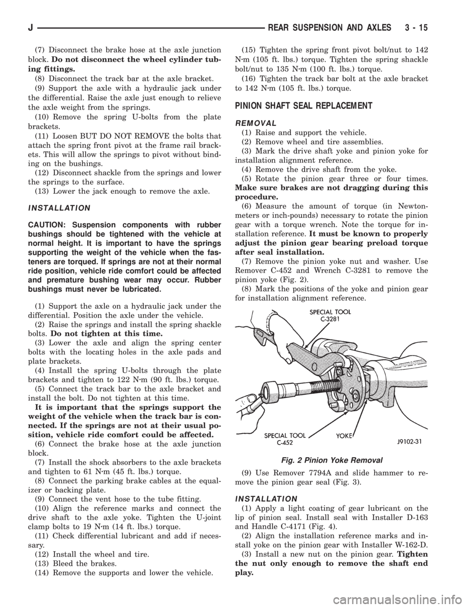
(7) Remove the pinion yoke nut and washer. Use
Remover C-452 and Wrench C-3281 to remove the
pinion yoke (Fig. 2).
(8) Mark the positions of the yoke and pinion gear
for installation alignment reference.
(9) Use Remover 7794A and slide hammer to re-
move the pinion gear seal (Fig. 3).
INSTALLATION
(1) Apply a light coating of gear lubricant on the
lip of pinion seal. Install seal with Installer D-163
and Handle C-4171 (Fig. 4).
(2) Align the installation reference marks and in-
stall yoke on the pinion gear with Installer W-162-D.
(3) Install a new nut on the pinion gear.Tighten
the nut only enough to remove the shaft end
play.
Fig. 2 Pinion Yoke Removal
JREAR SUSPENSION AND AXLES 3 - 15
Page 116 of 2198

LUBRICANT SPECIFICATIONS
Multi-purpose, hypoid gear lubricant should be
used in the 8 1/4 inch axle. The lubricant should
have MIL-L-2105C and API GL 5 quality specifica-
tions. MOPARtHypoid Gear Lubricant conforms to
both of these specifications.
²The factory installed lubricant for the 8 1/4 inch
rear axle is SAE 80W 90 gear lubricant.
²The factory installed lubricant quantity is 6762
fluid oz.
CAUTION: Overfilling the differential can result in
lubricant foaming and overheating.
Refer to Group 0, Lubrication and Maintenance for
additional information.
CAUTION: If axle is submerged in water, lubricant
must be replaced immediately to avoid possible
premature axle failure.
DRIVE AXLE ASSEMBLY REPLACEMENTÐXJ
VEHICLES
REMOVAL
(1) Raise the vehicle. Position support stands un-
der the frame rails slightly in front the springs.
(2) Remove the rear wheels.
(3) Mark the drive shaft yoke and axle pinion yoke
for alignment reference. Disconnect the drive shaft
from the axle.
(4) Disconnect the axle vent hose.
(5) Disconnect the parking brake cables at the
equalizer or backing plate.
(6) Disconnect the shock absorbers from the axle
brackets.
(7) Disconnect the brake hose at the axle junction
block.Do not disconnect the wheel cylinder tub-
ing fittings.
(8) If equipped, disconnect ABS wiring connections
at the axle.
(9) Support the axle with a hydraulic jack under
the differential.
(10) Remove the spring U-bolts from the plate
brackets.
(11) Lower the jack enough to remove the axle.
INSTALLATION
CAUTION: Suspension components with rubber
bushings should be tightened with the vehicle at
normal height. It is important to have the springs
supporting the weight of the vehicle when the fas-
teners are torqued. If springs are not at their normal
ride position, vehicle ride comfort could be affected
and premature bushing wear may occur. Rubber
bushings must never be lubricated.(1) Support the axle on a hydraulic jack under the
differential. Position the axle under the vehicle.
(2) Raise the axle and align the spring center bolts
with the locating holes in the axle pads and plate
brackets.
(3) Install the spring U-bolts through the plate
brackets and tighten to 70 Nzm (52 ft. lbs.) torque.
(4) Install ABS wiring connections (if equipped) at
the axle.
(5) Connect the brake hose at the axle junction
block.
(6) Install the shock absorbers to the axle brackets
and tighten to 62 Nzm (46 ft. lbs.) torque.
(7) Connect the parking brake cables at the equal-
izer or backing plate.
(8) Connect the vent hose to the tube fitting.
(9) Align the reference marks and connect the
drive shaft to the axle yoke. Tighten the U-joint
clamp bolts to 19 Nzm (14 ft. lbs.) torque.
(10) Check differential lubricant and add if neces-
sary.
(11) Install the wheel and tire.
(12) Bleed the brakes.
(13) Remove the supports and lower the vehicle.
LUBRICANT CHANGE
The gear lubricant will drain quicker if the vehicle
has been recently driven.
(1) Raise and support the vehicle.
(2) Remove the lubricant fill hole plug from the dif-
ferential housing cover.
(3) Remove the differential housing cover and
drain the lubricant from the housing.
(4) Clean the housing cavity with a flushing oil,
light engine oil or lint free cloth.Do not use water,
steam, kerosene or gasoline for cleaning.
(5) Remove the sealant from the housing and cover
surfaces. Use solvent to clean the mating surfaces.
(6) Apply a bead of MOPARtSilicone Rubber Seal-
ant to the housing cover (Fig. 2). Allow the sealant to
cure for a few minutes.
Install the housing cover within 5 minutes after
applying the sealant. If not installed the sealant
must be removed and another bead applied.
(7) Install the cover and any identification tag.
Tighten the cover bolts in a criss-cross pattern to 47
Nzm (35 ft. lbs.) torque.
(8) Refill the differential with Mopar Hypoid Gear
Lubricant 13 mm (1/2 in.) below the fill plug hole.
With Trac-Lok differentials, add a container of Mopar
Hypoid Gear Lubricant Additive.
CAUTION: Overfilling the differential can result in
lubricant foaming and overheating.
(9) Install the fill hole plug and lower the vehicle.
JREAR SUSPENSION AND AXLES 3 - 31
Page 141 of 2198
SERVICE BRAKE DIAGNOSIS
INDEX
page page
Brake Drag............................... 6
Brake Fade.............................. 6
Brake Fluid Contamination................... 7
Brake Noise.............................. 7
Brake Pull............................... 6
Brake Warning Light Operation................ 5
Brakes Do Not Hold After Driving Through Deep
Water Puddles........................... 7
Component Inspection...................... 5
Contaminated Brakelining.................... 7
Diagnosing Parking Brake Malfunctions.......... 8
Diagnosis Procedures....................... 4
General Information........................ 4Hard Pedal or High Pedal Effort............... 6
Low Pedal............................... 5
Master Cylinder/Power Booster Test............ 8
Pedal Falls Away.......................... 5
Pedal Pulsation (Non-ABS Brakes Only)......... 6
Power Booster Check Valve Test............... 9
Power Booster Vacuum Test.................. 9
Preliminary Brake Check..................... 4
Rear Brake Grab.......................... 7
Road Testing............................. 5
Spongy Pedal............................. 5
Wheel and Tire Problems.................... 7
GENERAL INFORMATION
The diagnosis information in this section covers
service brake components which include:
²disc brake calipers
²disc brakeshoes
²drum brake wheel cylinders
²drum brakeshoes and brake drums
²drum brake support plates
²parking brake mechanism
²master cylinder/combination valve
²vacuum power brake booster
²brake pedal and brakelight switch
²brake warning light
DIAGNOSIS PROCEDURES
Service brake diagnosis involves determining if a
problem is related to a mechanical, hydraulic or vac-
uum operated component. A preliminary brake check,
followed by road testing and component inspection
are needed to determine a problem cause.
Road testing will either verify proper brake opera-
tion or confirm the existence of a problem. Compo-
nent inspection will, in most cases, identify the
actual part responsible for a problem.
The first diagnosis step is the preliminary brake
check. This involves inspecting fluid level, parking
brake action, wheel and tire condition, checking for
obvious leaks or component damage and testing
brake pedal response. A road test will confirm or
deny the existence of a problem. The final diagnosis
procedure involves road test analysis and a visual in-
spection of brake components.
PRELIMINARY BRAKE CHECK
(1) If amber ABS light is illuminated, refer to ABS
Brake System Diagnosis. If red warning light is illu-
minated, or if neither warning light is illuminated,
continue with brake check.(2) Inspect condition of tires and wheels. Damaged
wheels and worn, damaged, or underinflated tires
can cause pull, shudder, tramp and a condition simi-
lar to grab.
(3) If complaint was based on noise when braking,
check suspension components. Jounce front and rear
of vehicle and listen for noise that might be caused
by loose, worn, or damaged suspension or steering
components.
(4) Inspect brake fluid level:
(a) If vehicle has one-piece master cylinder, fluid
level should be within 6 mm (1/4 in.) of reservoir
rim.
(b) If vehicle has nylon reservoir with single
filler cap, correct level is to FULL mark on side of
reservoir. Acceptable level is between FULL and
ADD marks.
(c) Remember that fluid level in the reservoir
compartments will decrease in proportion to nor-
mal lining wear. However, if fluid level is abnor-
mally low, look for leaks at calipers, wheel
cylinders, brakelines and master cylinder.
(5) Inspect brake fluid condition:
(a) Fluid should be free of foreign material.Note
that brake fluid tends to darken over time.
This is normal and should not be mistaken for
contamination. If fluid is clear of foreign ma-
terial, it is OK.
(b) If fluid is highly discolored, or appears to con-
tain foreign material, drain out a sample with a
clean suction gun. Pour sample in a glass container
and note condition described in step (c).
(c) If fluid separates into layers, obviously con-
tains oil, or a substance other than brake fluid,
system seals and cups will have to be replaced and
hydraulic system flushed.
(6) Check parking brake operation. Verify free
movement and full release of cables and foot pedal or
5 - 4 SERVICE BRAKE DIAGNOSISJ
Page 143 of 2198
pedal. The proper course of action is to bleed the sys-
tem, or replace thin drums and suspect quality brake
lines and hoses.
HARD PEDAL OR HIGH PEDAL EFFORT
A hard pedal or high pedal effort may be due to lin-
ing that is water soaked, contaminated, glazed, or
badly worn. The power booster or check valve could
also be faulty. Test the booster and valve as described
in this section.
BRAKE DRAG
Brake drag occurs when the lining is in constant
contact with the rotor or drum. Drag can occur at one
wheel, all wheels, fronts only, or rears only. It is a
product of incomplete brakeshoe release. Drag can be
minor or severe enough to overheat the linings, ro-
tors and drums. A drag condition also worsens as
temperature of the brake parts increases.
Brake drag also has a direct effect on fuel economy.
If undetected, minor brake drag can be misdiagnosed
as an engine or transmission/torque converter prob-
lem.
Minor drag will usually cause slight surface char-
ring of the lining. It can also generate hard spots in
rotors and drums from the overheat/cool down pro-
cess. In most cases, the rotors, drums, wheels and
tires are quite warm to the touch after the vehicle is
stopped.
Severe drag can char the brake lining all the way
through. It can also distort and score rotors and
drums to the point of replacement. The wheels, tires
and brake components will be extremely hot. In se-
vere cases, the lining may generate smoke as it chars
from overheating.
An additional cause of drag involves the use of in-
correct length caliper mounting bolts. Bolts that are
too long can cause a partial apply condition. The cor-
rect caliper bolts have a shank length of 67 mm
(2.637 in.), plus or minus 0.6 mm (0.0236 in.). Refer
to the Disc Brake service section for more detail on
caliper bolt dimensions and identification.
Some common causes of brake drag are:
²loose or damaged wheel bearing
²seized or sticking caliper or wheel cylinder piston
²caliper binding on bolts or slide surfaces
²wrong length caliper mounting bolts (too long)
²loose caliper mounting bracket
²distorted rotor, brake drum, or shoes
²brakeshoes binding on worn/damaged support
plates
²severely rusted/corroded components
²misassembled components.
If brake drag occurs at all wheels, the problem may
be related to a blocked master cylinder compensatorport or faulty power booster (binds-does not release).
The condition will worsen as brake temperature in-
creases.
The brakelight switch can also be a cause of drag.
An improperly mounted or adjusted brakelight
switch can prevent full brake pedal return. The re-
sult will be the same as if the master cylinder com-
pensator ports are blocked. The brakes would be
partially applied causing drag.
BRAKE FADE
Brake fade is a product of overheating caused by
brake drag. However, overheating and subsequent
fade can also be caused by riding the brake pedal,
making repeated high deceleration stops in a short
time span, or constant braking on steep roads. Refer
to the Brake Drag information in this section for
causes.
PEDAL PULSATION (NON-ABS BRAKES ONLY)
Pedal pulsation is caused by parts that are loose,
or beyond tolerance limits. This type of pulsation is
constant and will occur every time the brakes are ap-
plied.
Disc brake rotors with excessive lateral runout or
thickness variation, or out of round brake drums are
the primary causes of pulsation.
On vehicles with ABS brakes, remember that pedal
pulsation is normal during antilock mode brake
stops. If pulsation occurs during light to moderate
brake stops, a standard brake part is either loose, or
worn beyond tolerance.
BRAKE PULL
A front pull condition could be the result of:
²contaminated lining in one caliper
²seized caliper piston
²binding caliper
²wrong caliper mounting bolts (too long)
²loose caliper
²loose or corroded mounting bolts
²improper brakeshoes
²damaged rotor
²incorrect wheel bearing adjustment (at one wheel)
A worn, damaged wheel bearing or suspension com-
ponent are further causes of pull. A damaged front
tire (bruised, ply separation) can also cause pull.
Wrong caliper bolts (too long) will cause a partial ap-
ply condition and pull if only one caliper is involved.
A common and frequently misdiagnosed pull condi-
tion is where direction of pull changes after a few
stops. The cause is a combination of brake drag fol-
lowed by fade at the dragging brake unit.
As the dragging brake overheats, efficiency is so re-
duced that fade occurs. If the opposite brake unit is
still functioning normally, its braking effect is magni-
5 - 6 SERVICE BRAKE DIAGNOSISJ
Page 147 of 2198
BRAKE FLUIDÐBRAKE BLEEDINGÐBRAKELINES AND HOSES
INDEX
page page
Brake Bleeding (With ABS Brakes)............ 11
Brake Bleeding (With Standard Brakes)......... 11
Brake Bleeding Recommendations............ 10
Brake Fluid Contamination.................. 10Brake Fluid Level......................... 10
Brakeline Charts.......................... 12
Brakelines and Hoses...................... 12
Recommended Brake Fluid.................. 10
RECOMMENDED BRAKE FLUID
Recommended brake fluid for Jeep vehicles is Mo-
par brake fluid, or an equivalent fluid meeting SAE
J1703 and DOT 3 standards. The recommendation
applies to models with standard or ABS brakes.
Use new brake fluid to top off the master cyl-
inder or refill the system. Never use reclaimed
fluid, fluid not meeting the SAE/DOT standards
or fluid from an unsealed container. Do not use
fluid from any container that has been left
open for any length of time. Fluid in open con-
tainers can absorb moisture.
BRAKE FLUID LEVEL
Always clean the master cylinder reservoir and
cover or cap before adding fluid. This avoids having
dirt from the cap or reservoir exterior fall into the
fluid.
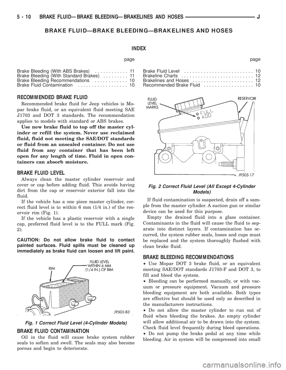
If the vehicle has a one piece master cylinder, cor-
rect fluid level is to within 6 mm (1/4 in.) of the res-
ervoir rim (Fig. 1).
If the vehicle has a plastic reservoir with a single
cap, preferred fluid level is to the FULL mark (Fig.
2).
CAUTION: Do not allow brake fluid to contact
painted surfaces. Fluid spills must be cleaned up
immediately as brake fluid can loosen and lift paint.
BRAKE FLUID CONTAMINATION
Oil in the fluid will cause brake system rubber
seals to soften and swell. The seals may also become
porous and begin to deteriorate.If fluid contamination is suspected, drain off a sam-
ple from the master cylinder. A suction gun or similar
device can be used for this purpose.
Empty the drained fluid into a glass container.
Contaminants in the fluid will cause the fluid to sep-
arate into distinct layers. If contamination has oc-
curred, the system rubber seals, hoses and cups must
be replaced and the system thoroughly flushed with
clean brake fluid.
BRAKE BLEEDING RECOMMENDATIONS
²Use Mopar DOT 3 brake fluid, or an equivalent
meeting SAE/DOT standards J1703-F and DOT 3, to
fill and bleed the system.
²Bleeding can be performed manually, or with vac-
uum or pressure equipment. Vacuum and pressure
bleeding equipment are both available. Both types
are effective but should be used only as described in
the manufacturers instructions.
²Do not allow the master cylinder to run out of
fluid when bleeding the brakes. An empty cylinder
will allow additional air to be drawn into the system.
Check fluid level frequently during bleed operations.
²Do not pump the brake pedal at any time while
bleeding. Air in system will be compressed into small
Fig. 1 Correct Fluid Level (4-Cylinder Models)
Fig. 2 Correct Fluid Level (All Except 4-Cylinder
Models)
5 - 10 BRAKE FLUIDÐBRAKE BLEEDINGÐBRAKELINES AND HOSESJ
Page 149 of 2198
connect scan tool and proceed to next step.
(7)Repeatconventional bleed procedure described
in steps (4) and (5).
(8) Top off master cylinder fluid level and verify
proper brake operation before moving vehicle.
BRAKELINES AND HOSES
Metal brakelines and rubber brake hoses should be
inspected periodically and replaced if damaged.
Rubber brake hoses should be replaced if cut,
cracked, swollen, or leaking. Rubber hoses must be
replaced as they are not repairable.
Steel brakelines should be inspected any time the
vehicle is in for normal maintenance. This is impor-
tant on high mileage vehicles. It is especially impor-
tant when the vehicle is operated on roads that are
salted during winter months.
Heavily rusted/corroded brake rotors, drums,
support plates, and brakelines should be
cleaned and carefully inspected. Heavy rust
buildup can hide severe damage to a compo-
nent. Severely rusted parts should be replaced
if condition is suspect.
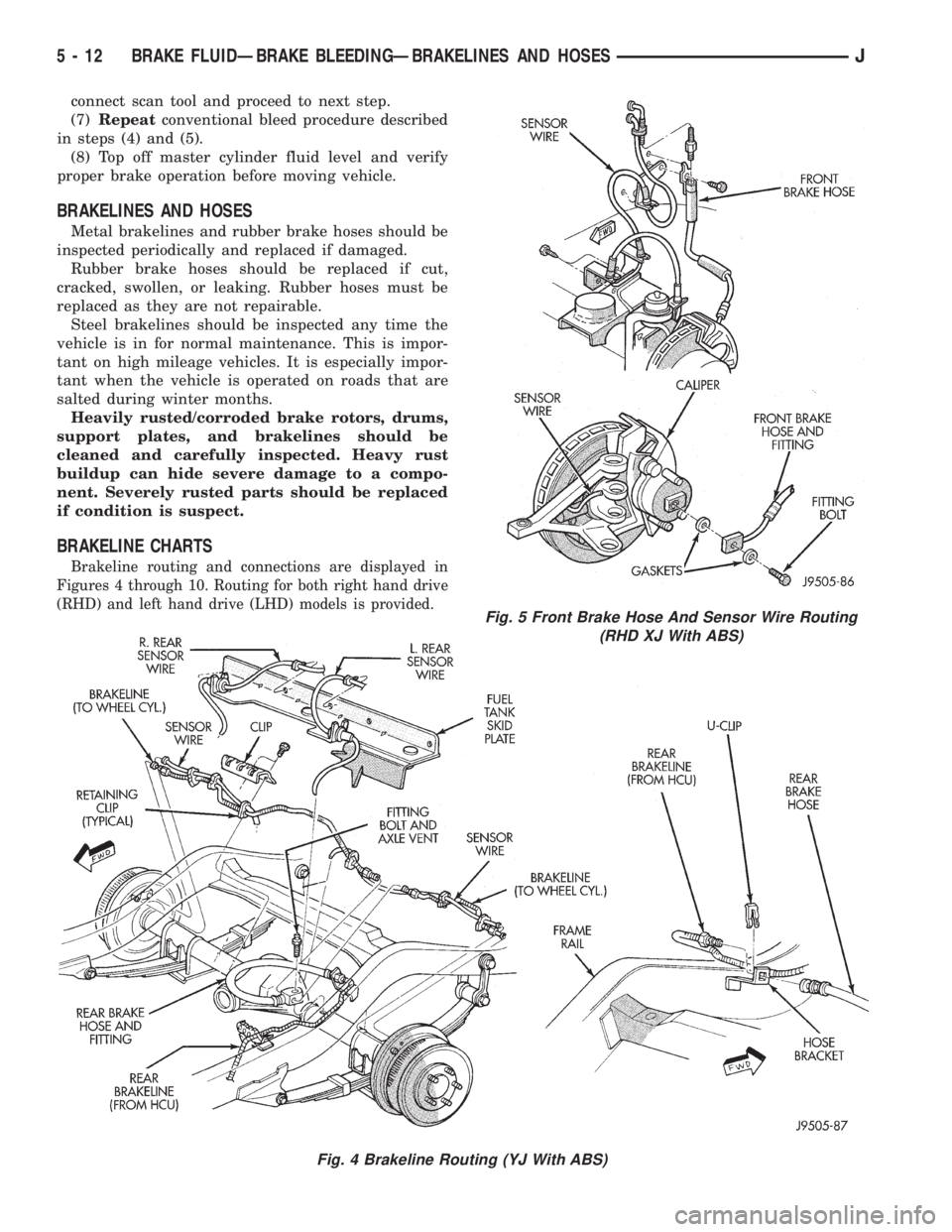
BRAKELINE CHARTS
Brakeline routing and connections are displayed in
Figures 4 through 10. Routing for both right hand drive
(RHD) and left hand drive (LHD) models is provided.
Fig. 4 Brakeline Routing (YJ With ABS)
Fig. 5 Front Brake Hose And Sensor Wire Routing
(RHD XJ With ABS)
5 - 12 BRAKE FLUIDÐBRAKE BLEEDINGÐBRAKELINES AND HOSESJ
Page 152 of 2198
MASTER CYLINDERÐCOMBINATION VALVE
INDEX
page page
Combination Valve Replacement (Non-ABS)..... 16
General Service Information................. 15
Master Cylinder and Combination Valve Installation
(With ABS)............................. 20
Master Cylinder and Combination Valve Removal
(With ABS)............................. 17Master Cylinder Bench Bleeding.............. 21
Master Cylinder Installation (Non-ABS)......... 16
Master Cylinder Overhaul (4-Cylinder Models).... 16
Master Cylinder Removal (Non-ABS)........... 15
Reservoir Replacement (2-Piece Master Cylinder) . 19
GENERAL SERVICE INFORMATION
Master Cylinder
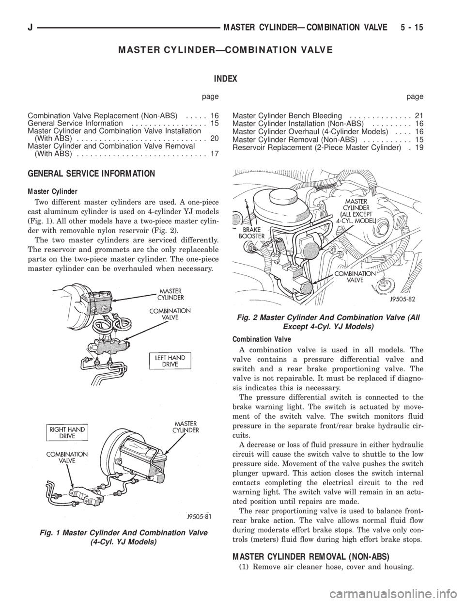
Two different master cylinders are used. A one-piece
cast aluminum cylinder is used on 4-cylinder YJ models
(Fig. 1). All other models have a two-piece master cylin-
der with removable nylon reservoir (Fig. 2).
The two master cylinders are serviced differently.
The reservoir and grommets are the only replaceable
parts on the two-piece master cylinder. The one-piece
master cylinder can be overhauled when necessary.
Combination Valve
A combination valve is used in all models. The
valve contains a pressure differential valve and
switch and a rear brake proportioning valve. The
valve is not repairable. It must be replaced if diagno-
sis indicates this is necessary.
The pressure differential switch is connected to the
brake warning light. The switch is actuated by move-
ment of the switch valve. The switch monitors fluid
pressure in the separate front/rear brake hydraulic cir-
cuits.
A decrease or loss of fluid pressure in either hydraulic
circuit will cause the switch valve to shuttle to the low
pressure side. Movement of the valve pushes the switch
plunger upward. This action closes the switch internal
contacts completing the electrical circuit to the red
warning light. The switch valve will remain in an actu-
ated position until repairs are made.
The rear proportioning valve is used to balance front-
rear brake action. The valve allows normal fluid flow
during moderate effort brake stops. The valve only con-
trols (meters) fluid flow during high effort brake stops.
MASTER CYLINDER REMOVAL (NON-ABS)
(1) Remove air cleaner hose, cover and housing.
Fig. 1 Master Cylinder And Combination Valve
(4-Cyl. YJ Models)
Fig. 2 Master Cylinder And Combination Valve (All
Except 4-Cyl. YJ Models)
JMASTER CYLINDERÐCOMBINATION VALVE 5 - 15