1995 JEEP CHEROKEE steering
[x] Cancel search: steeringPage 487 of 2198
(9) Allow epoxy to cure 24 hours at room tempera-
ture or use heat gun with a 260É-371ÉC (500É-700ÉF)
range for 15 minutes. Hold gun approximately
254mm (10 inches) from repaired area.
(10) After conductive epoxy is properly cured re-
move wedge or clamp from terminal or pigtail and
check operation of rear window defogger. Do not at-
tach connectors until curing is complete.
DEFOGGER SWITCH REMOVE/INSTALL
XJ MODELS
(1) Remove the instrument cluster bezel. Refer to
Group 8E - Instrument Panel and Gauges for proce-
dure.
(2) Remove the switch housing panel.
(3) Unplug the switch connector. Slightly depress
the switch mounting tabs and remove the switch.
(4) Reverse removal procedures to install.
YJ MODELS
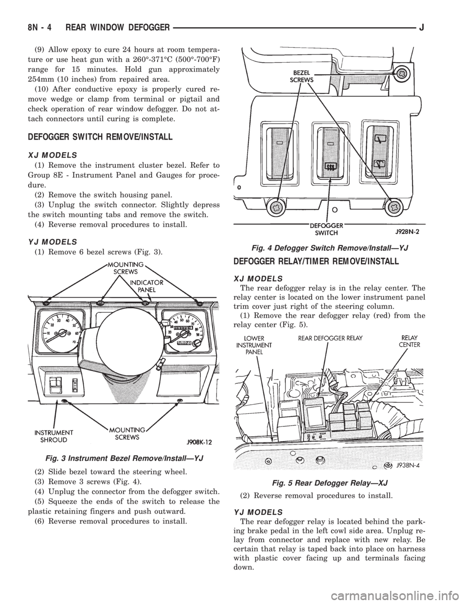
(1) Remove 6 bezel screws (Fig. 3).
(2) Slide bezel toward the steering wheel.
(3) Remove 3 screws (Fig. 4).
(4) Unplug the connector from the defogger switch.
(5) Squeeze the ends of the switch to release the
plastic retaining fingers and push outward.
(6) Reverse removal procedures to install.
DEFOGGER RELAY/TIMER REMOVE/INSTALL
XJ MODELS
The rear defogger relay is in the relay center. The
relay center is located on the lower instrument panel
trim cover just right of the steering column.
(1) Remove the rear defogger relay (red) from the
relay center (Fig. 5).
(2) Reverse removal procedures to install.
YJ MODELS
The rear defogger relay is located behind the park-
ing brake pedal in the left cowl side area. Unplug re-
lay from connector and replace with new relay. Be
certain that relay is taped back into place on harness
with plastic cover facing up and terminals facing
down.
Fig. 3 Instrument Bezel Remove/InstallÐYJ
Fig. 4 Defogger Switch Remove/InstallÐYJ
Fig. 5 Rear Defogger RelayÐXJ
8N - 4 REAR WINDOW DEFOGGERJ
Page 488 of 2198
POWER LOCKS
CONTENTS
page page
DIAGNOSIS............................. 2
GENERAL INFORMATION.................. 1SERVICE PROCEDURES................... 8
GENERAL INFORMATION
Power locks are optional equipment on XJ (Chero-
kee) models. Power windows and the keyless entry
system are included on vehicles equipped with the
power lock option. All doors and the liftgate can be
locked and unlocked electrically by operating the
switch on either front door panel, or by operating the
lock and unlock buttons of the remote keyless entry
transmitter. The power lock and keyless entry sys-
tems operate with battery power supplied indepen-
dent of the ignition switch.
Following are general descriptions of the major
components in the power lock system. Refer to Group
8W - Wiring Diagrams for complete circuit descrip-
tions and diagrams. Refer to the owner's manual for
more information on the features and use of these
systems.
POWER LOCK SWITCH
The power locks are controlled by a two-way switch
mounted on the trim panel of each front door. The
switch controls battery feed to the lock and unlock
relays. The door lock switches can not be repaired. If
faulty, the entire switch must be replaced.
POWER LOCK/UNLOCK RELAYS
The power lock and unlock relays are located in the
relay center. The relay center is located on the lower
instrument panel reinforcement behind the lower in-
strument panel and just right of the steering column.
The relays respond to inputs from the power lock
switches and the keyless entry module by sending
the correct battery and ground feeds to the lock mo-
tors. The lock and unlock relays can not be repaired.
If faulty, they must be replaced.
POWER LOCK MOTOR
The locks are actuated by a reversible motor
mounted within each door. The motor direction iscontrolled by the battery and ground feeds from the
power lock/unlock relays. The motor can not be re-
paired. If faulty, the entire motor must be replaced.
KEYLESS ENTRY TRANSMITTER
The keyless entry transmitter is equipped with two
buttons labeled Lock and Unlock. It is also designed
to serve as a key fob and is equipped with a key ring.
Each transmitter has a different vehicle access code,
which must be programmed into the memory of the
keyless entry module in the vehicle in order to oper-
ate the locks. The operating range of the infrared
transmitter signal is up to 4.75 meters (15 feet) from
the receiver.
The transmitter operates on two CR1616 3-volt (or
equivalent) batteries. Typical battery life is from one
to two years.
KEYLESS ENTRY MODULE
The keyless entry module is mounted in a housing
on the headliner near the windshield between the
sunvisors, or inside and towards the rear of the over-
head console (if equipped). This module contains the
keyless entry receiver and program logic for the key-
less entry system.
The keyless entry module has a memory function
to retain the vehicle access code of at least one, and
up to four transmitters. The module receives input
from the remote keyless entry transmitter. In re-
sponse to that input, it is programmed to control out-
puts to the lock and unlock relays. The module can
not be repaired and, if faulty, must be replaced.
JPOWER LOCKS 8P - 1
Page 499 of 2198
(8) Reverse removal procedures to install. Be sure
to flex housing outward near the keyless entry mod-
ule until the console snaps onto the rear mounting
bracket.
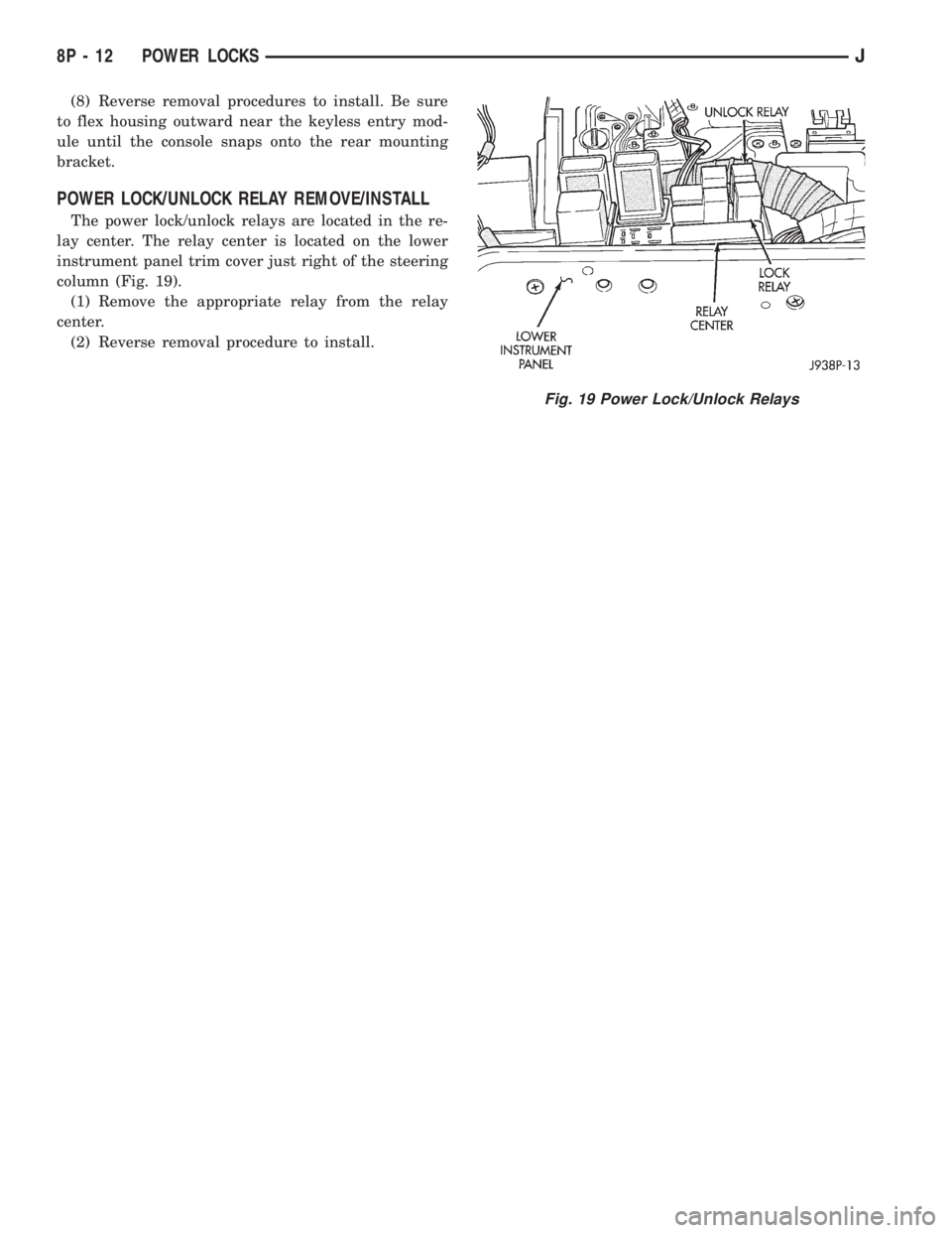
POWER LOCK/UNLOCK RELAY REMOVE/INSTALL
The power lock/unlock relays are located in the re-
lay center. The relay center is located on the lower
instrument panel trim cover just right of the steering
column (Fig. 19).
(1) Remove the appropriate relay from the relay
center.
(2) Reverse removal procedure to install.
Fig. 19 Power Lock/Unlock Relays
8P - 12 POWER LOCKSJ
Page 518 of 2198
CHIME/BUZZER WARNING SYSTEMS
CONTENTS
page page
DIAGNOSIS............................. 2
GENERAL INFORMATION.................. 1SERVICE PROCEDURES................... 4
GENERAL INFORMATION
This group covers the buzzer warning system,
which is standard equipment on XJ (Cherokee)/YJ
(Wrangler) models. The system provides an audible
warning to the driver when it monitors the following
conditions:
²key is in ignition switch with the driver's door
open
²head or park lamps are on with driver's door open
(XJ only)
²driver's seat belt is not buckled with ignition
switch in ON position.
Following are general descriptions of the major
components in the buzzer warning system. Refer to
Group 8W - Wiring Diagrams for complete circuit de-
scriptions and diagrams.
BUZZER MODULE
The buzzer module is located in the fuseblock mod-
ule under the left end of the instrument panel. It re-
ceives battery voltage at all times from (fuse 15 - XJ,
fuse 3 - YJ) the fuseblock module. It also receives a
second battery feed (fuse 17 - XJ, fuse 9 - YJ) when
the ignition switch is in the ON or START position.
Other inputs to the module include the driver's door
jamb switch, the driver's seat belt switch, the ignition
key-in switch, and the headlamp switch (XJ only). The
only output of the module is a timed 4 to 8 second feed
to the seat belt reminder lamp in the message center of
the instrument cluster. The timer function begins after
the ignition switch is turned to the ON position.
The buzzer module can not be repaired. If faulty, it
must be replaced.
DRIVER'S DOOR JAMB SWITCH
The driver's door jamb switch is mounted to the
driver's door hinge pillar. The switch closes a path to
ground for the buzzer module through the key-in
switch or headlamp switch (XJ only) when the driv-
er's door is opened, and opens when the driver's door
is closed. This switch can not be repaired. If faulty, it
must be replaced.
IGNITION KEY-IN SWITCH
XJ MODELS
The key-in switch is integral to the ignition switch,
which is mounted on the right side of the steering col-
umn. It closes a path to ground for the buzzer module
when the ignition key is inserted in the ignition lock cyl-
inder and the driver's door jamb switch is closed (door
open). The switch opens when the key is removed from
the ignition lock cylinder. This switch can not be re-
paired. If faulty, the entire ignition switch must be re-
placed. Refer to Group 8D - Ignition Systems for service
procedures.
YJ MODELS
The key-in switch is mounted within the steering col-
umn in the lock cylinder housing. It closes a path to
ground for the buzzer module when the ignition key is
inserted in the ignition lock cylinder and the driver's
door jamb switch is closed (door open). The switch opens
when the key is removed from the ignition lock cylinder.
This switch is available for service replacement. Refer
to Group 19 - Steering for service procedures.
HEADLAMP SWITCH (XJ ONLY)
The headlamp switch is located in the instrument
panel. It closes a path to ground for the buzzer module
when the park or headlamps are on and the driver's
door jamb switch is closed (door open). The switch opens
the ground path when the park and headlamps are
turned off. The headlamp switch can not be repaired. If
faulty, it must be replaced. Refer to Group 8E - Instru-
ment Panel and Gauges for service procedures.
DRIVER'S SEAT BELT SWITCH
The driver's seat belt switch is integral to the driv-
er's seat belt buckle-half assembly. The switch is nor-
mally closed, providing a ground path to the buzzer
module. When the tip-half of the seat belt is inserted
into the seat belt buckle, the switch opens the buzzer
module ground path. The seat belt switch can not be
repaired. If faulty, the entire driver's seat belt buck-
le-half must be replaced. Refer to Group 23 - Body
Components for service procedures.
JCHIME/BUZZER WARNING SYSTEMS 8U - 1
Page 519 of 2198
DIAGNOSIS
BUZZER MODULE
(1) Check fuses (15 and 17 - XJ, 3 and 9 - YJ) in
the fuseblock module. If fuses are OK, go to next
step. If not OK, replace fuses as required.
(2) Check for battery voltage at fuse (15 - XJ, 3 -
YJ) in fuseblock module. If OK, go to next step. If not
OK, repair feed circuit from power distribution center
as required.
(3) Turn ignition switch to ON position. Check for
battery voltage at fuse (17 - XJ, 9 - YJ) in the fuse-
block module. If OK, go to next step. If not OK, re-
pair feed from ignition switch as required.
(4) Turn ignition switch to OFF position. Replace
buzzer module with a known good unit and test op-
eration. If not OK, remove buzzer module and go to
next step.
(5) Check for battery voltage at cavity for buzzer
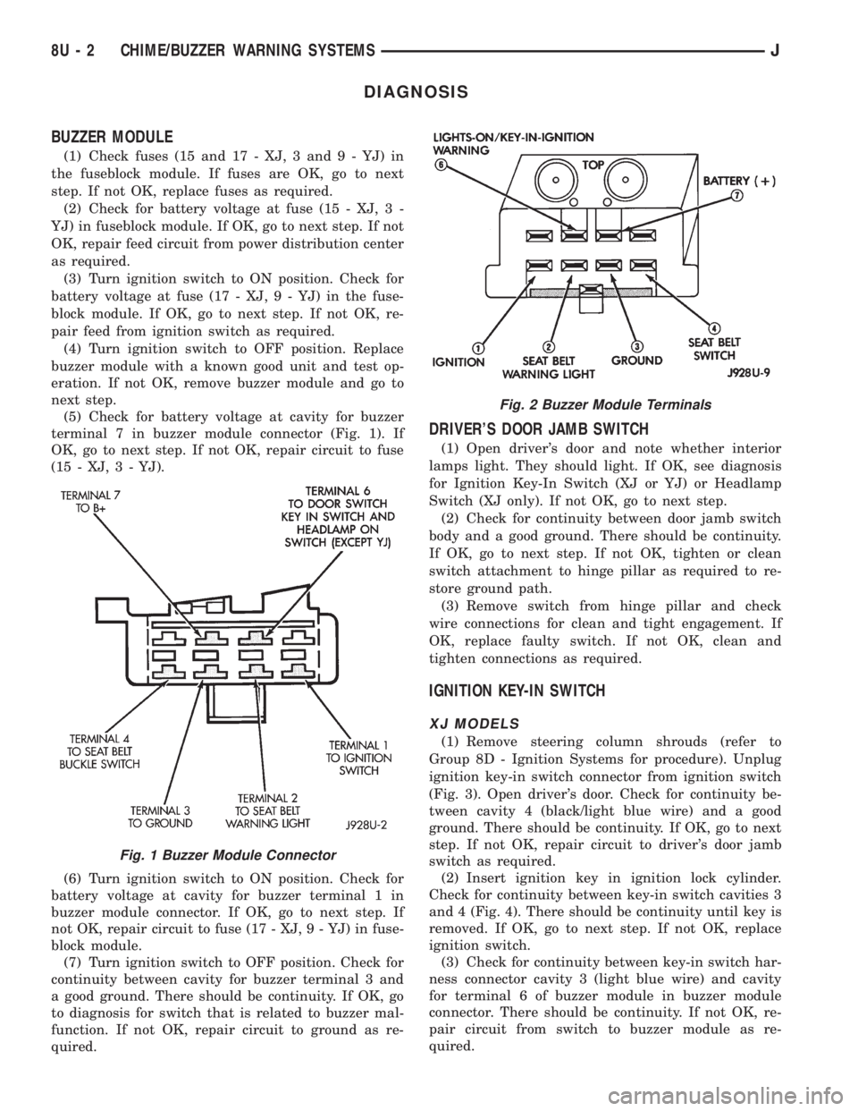
terminal 7 in buzzer module connector (Fig. 1). If
OK, go to next step. If not OK, repair circuit to fuse
(15 - XJ, 3 - YJ).
(6) Turn ignition switch to ON position. Check for
battery voltage at cavity for buzzer terminal 1 in
buzzer module connector. If OK, go to next step. If
not OK, repair circuit to fuse (17 - XJ, 9 - YJ) in fuse-
block module.
(7) Turn ignition switch to OFF position. Check for
continuity between cavity for buzzer terminal 3 and
a good ground. There should be continuity. If OK, go
to diagnosis for switch that is related to buzzer mal-
function. If not OK, repair circuit to ground as re-
quired.
DRIVER'S DOOR JAMB SWITCH
(1) Open driver's door and note whether interior
lamps light. They should light. If OK, see diagnosis
for Ignition Key-In Switch (XJ or YJ) or Headlamp
Switch (XJ only). If not OK, go to next step.
(2) Check for continuity between door jamb switch
body and a good ground. There should be continuity.
If OK, go to next step. If not OK, tighten or clean
switch attachment to hinge pillar as required to re-
store ground path.
(3) Remove switch from hinge pillar and check
wire connections for clean and tight engagement. If
OK, replace faulty switch. If not OK, clean and
tighten connections as required.
IGNITION KEY-IN SWITCH
XJ MODELS
(1) Remove steering column shrouds (refer to
Group 8D - Ignition Systems for procedure). Unplug
ignition key-in switch connector from ignition switch
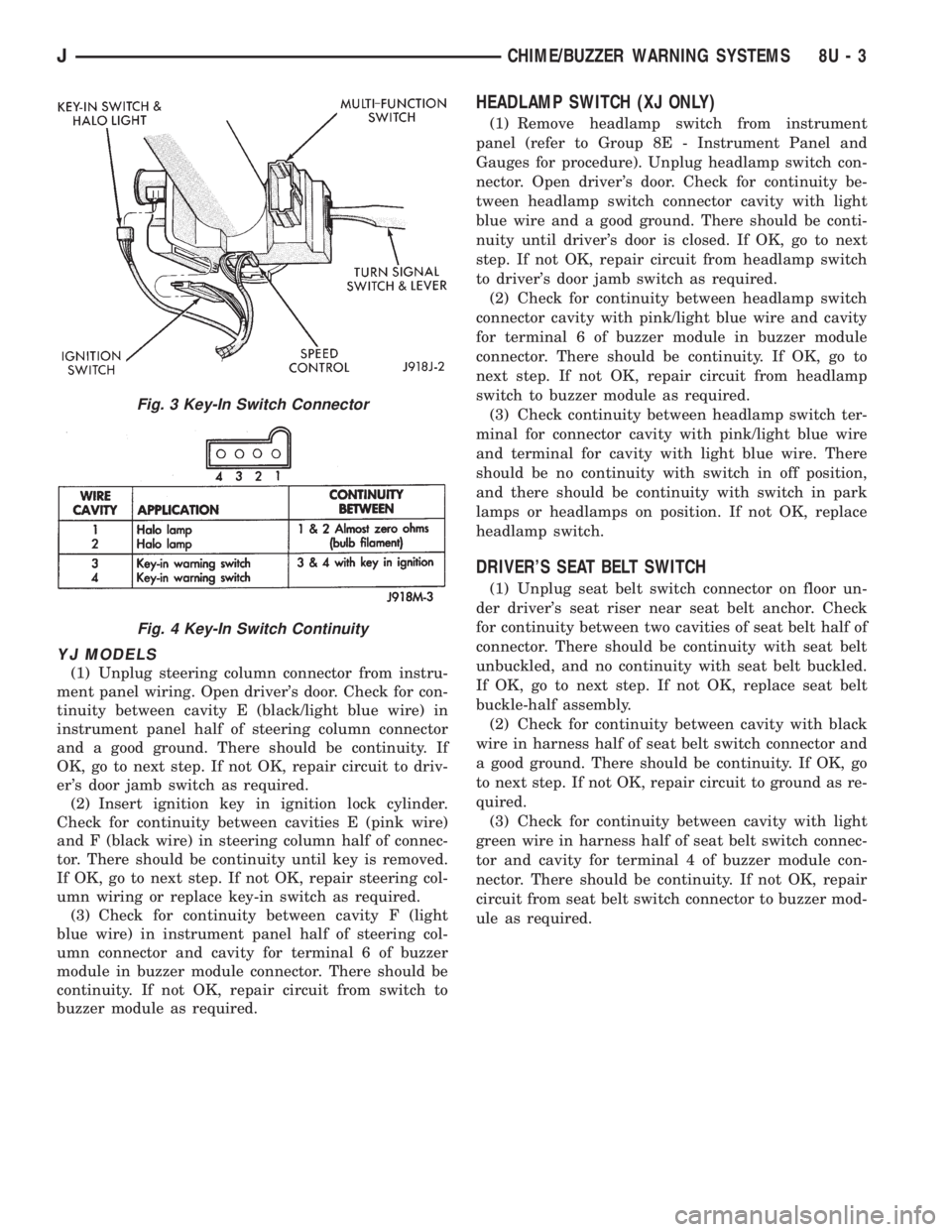
(Fig. 3). Open driver's door. Check for continuity be-
tween cavity 4 (black/light blue wire) and a good
ground. There should be continuity. If OK, go to next
step. If not OK, repair circuit to driver's door jamb
switch as required.
(2) Insert ignition key in ignition lock cylinder.
Check for continuity between key-in switch cavities 3
and 4 (Fig. 4). There should be continuity until key is
removed. If OK, go to next step. If not OK, replace
ignition switch.
(3) Check for continuity between key-in switch har-
ness connector cavity 3 (light blue wire) and cavity
for terminal 6 of buzzer module in buzzer module
connector. There should be continuity. If not OK, re-
pair circuit from switch to buzzer module as re-
quired.
Fig. 1 Buzzer Module Connector
Fig. 2 Buzzer Module Terminals
8U - 2 CHIME/BUZZER WARNING SYSTEMSJ
Page 520 of 2198
YJ MODELS
(1) Unplug steering column connector from instru-
ment panel wiring. Open driver's door. Check for con-
tinuity between cavity E (black/light blue wire) in
instrument panel half of steering column connector
and a good ground. There should be continuity. If
OK, go to next step. If not OK, repair circuit to driv-
er's door jamb switch as required.
(2) Insert ignition key in ignition lock cylinder.
Check for continuity between cavities E (pink wire)
and F (black wire) in steering column half of connec-
tor. There should be continuity until key is removed.
If OK, go to next step. If not OK, repair steering col-
umn wiring or replace key-in switch as required.
(3) Check for continuity between cavity F (light
blue wire) in instrument panel half of steering col-
umn connector and cavity for terminal 6 of buzzer
module in buzzer module connector. There should be
continuity. If not OK, repair circuit from switch to
buzzer module as required.
HEADLAMP SWITCH (XJ ONLY)
(1) Remove headlamp switch from instrument
panel (refer to Group 8E - Instrument Panel and
Gauges for procedure). Unplug headlamp switch con-
nector. Open driver's door. Check for continuity be-
tween headlamp switch connector cavity with light
blue wire and a good ground. There should be conti-
nuity until driver's door is closed. If OK, go to next
step. If not OK, repair circuit from headlamp switch
to driver's door jamb switch as required.
(2) Check for continuity between headlamp switch
connector cavity with pink/light blue wire and cavity
for terminal 6 of buzzer module in buzzer module
connector. There should be continuity. If OK, go to
next step. If not OK, repair circuit from headlamp
switch to buzzer module as required.
(3) Check continuity between headlamp switch ter-
minal for connector cavity with pink/light blue wire
and terminal for cavity with light blue wire. There
should be no continuity with switch in off position,
and there should be continuity with switch in park
lamps or headlamps on position. If not OK, replace
headlamp switch.
DRIVER'S SEAT BELT SWITCH
(1) Unplug seat belt switch connector on floor un-
der driver's seat riser near seat belt anchor. Check
for continuity between two cavities of seat belt half of
connector. There should be continuity with seat belt
unbuckled, and no continuity with seat belt buckled.
If OK, go to next step. If not OK, replace seat belt
buckle-half assembly.
(2) Check for continuity between cavity with black
wire in harness half of seat belt switch connector and
a good ground. There should be continuity. If OK, go
to next step. If not OK, repair circuit to ground as re-
quired.
(3) Check for continuity between cavity with light
green wire in harness half of seat belt switch connec-
tor and cavity for terminal 4 of buzzer module con-
nector. There should be continuity. If not OK, repair
circuit from seat belt switch connector to buzzer mod-
ule as required.
Fig. 3 Key-In Switch Connector
Fig. 4 Key-In Switch Continuity
JCHIME/BUZZER WARNING SYSTEMS 8U - 3
Page 521 of 2198
SERVICE PROCEDURES
Service procedures for components of the buzzer
system can be found in the appropriate group as fol-
lows:
²driver's door jamb switch - refer to Group 8L -
Lamps
²ignition key-in switch (XJ) - refer to Group 8D -
Ignition Systems²ignition key-in switch (YJ) - refer to Group 19 -
Steering
²headlamp switch - refer to Group 8E - Instrument
Panel and Gauges
²driver's seat belt switch - refer to Group 23 - Body
Components.
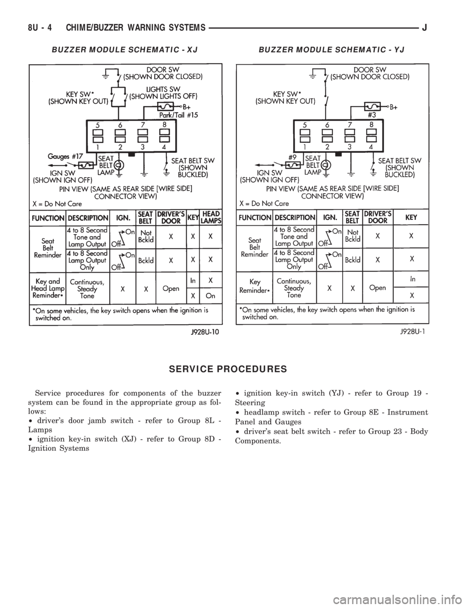
BUZZER MODULE SCHEMATIC - XJBUZZER MODULE SCHEMATIC - YJ
8U - 4 CHIME/BUZZER WARNING SYSTEMSJ
Page 576 of 2198
FUEL/IGNITION
INDEX
page page
Automatic Shut Down (ASD) Relay............. 1
Battery Feed.............................. 1
Brake Switch Input......................... 5
Camshaft Position Sensor.................... 3
CCDBus ................................ 5
Crankshaft Position Sensor................... 3
Data Link Connector........................ 5
Diagram Index Ð2.5L Engine.................. 6
Diagram Index Ð4.0L Engine.................. 6
Engine Coolant Temperature Sensor............ 3
Extended Idle Switch....................... 5
Fuel Injectors............................. 1
Fuel Pump Module......................... 2
Fuel Pump Relay.......................... 2
Heated Oxygen Sensor...................... 3Idle Air Control (IAC) Motor................... 2
Ignition Coil.............................. 2
Ignition Switch............................ 1
Intake Air Temperature Sensor................ 4
Malfunction Indicator Lamp (MIL)............... 5
Manifold Absolute Pressure Sensor............. 4
Park/Neutral Position Switch.................. 4
Power (Device) Ground...................... 5
Power Steering Pressure Switch............... 5
Tachometer Signal......................... 5
Throttle Position Sensor..................... 4
Torque Converter Clutch (TCC) Solenoid and
Relay................................. 4
Upshift Lamp............................. 5
Vehicle Speed Sensor....................... 2
IGNITION SWITCH
Circuit A1 from fuse 11 in the power distribution
center (PDC), supplies battery voltage to the ignition
switch. Depending upon position, the ignition switch
powers circuits A21, A38, A41, or A48.
START POSITION
In the START position, the ignition switch connects
circuit A1 to circuit A41. Circuit A41 connects to the
coil side of the starter motor relay.
Additionally in the START position, the case
grounded ignition switch provides ground for the
brake lamp switch and the warning lamps in the
instrument cluster.
START OR RUN POSITION
In the START or RUN position, the ignition switch
connects circuit A1 to circuit A21. Circuit A21 splices
to power fuse 17 in the fuse block and the coil side of
the Automatic Shut Down (ASD) relay and the fuel
pump relay.
RUN (ONLY) POSITION
When the ignition switch is in the RUN position, it
connects circuit A1 to circuit A38. Circuit A22 splices
to power fuses 1 and 7 in the fuse block.
²Fuse 1 powers the rear wiper system on circuit
V15.
²Fuse 7 feeds the Anti-Lock Brake System (ABS) on
circuit 236.
ACCESSORY OR RUN POSITIONS
In the ACCESSORY or RUN positions, the ignition
switch connects circuit A1 to circuit A48. Circuit A48
connects to a bus bar in the fuse block that feeds
fuses 2, 5, and 8.
AUTOMATIC SHUT DOWN (ASD) RELAY
When the ignition switch is in either the START or
RUN positions, it connects circuit A1 from fuse 6 in
the Power Distribution Center (PDC) to circuit A21.
Circuit A21 supplies battery voltage to the coil side of
the Automatic Shut Down (ASD) relay. The Power-
train Control Module (PCM) provides ground for the
relay on circuit K51. Circuit K51 connects to cavity 51
of the PCM.
When the PCM grounds the ASD relay, contacts
inside the relay close and connect circuit A18 from
fuse 14 in the PDC to circuit A142. Circuit A142
splices to the generator field terminal, fuel injectors,
and ignition coil. Circuit A142 also connects to cavity
57 of the PCM.
HELPFUL INFORMATION
²Along with supplying voltage to the coil side of the
ASD relay, circuit A21 also supplies voltage to the coil
side of the fuel pump relay.
BATTERY FEED
Circuit A14 from fuse 2 in the Power Distribution
Center (PDC) supplies battery voltage to cavity 3 of
the powertrain control module.
HELPFUL INFORMATION
Circuit A14 also supplies power to the contact sides
of the fuel pump relay and fuse F2 in the PDC. Fuse
F2 powers circuit A18 which supplies voltage to the
contact side of the automatic shut down relay.
FUEL INJECTORS
When the Automatic Shut Down (ASD) relay con-
tacts close, they connect circuits A14 and A142. Cir-
J8W-30 FUEL/IGNITIONÐXJ VEHICLES 8W - 30 - 1