1995 JEEP CHEROKEE steering
[x] Cancel search: steeringPage 432 of 2198
The liftgate wiper motor can not be repaired. If
faulty, the entire assembly must be replaced.
WINDSHIELD WIPER/WASHER SWITCH
Controls for the windshield wiper and washer sys-
tems are contained in the turn signal switch lever.
The turn signal switch lever is mounted on the left
side of the steering column between the steering
wheel and the instrument panel. The wiper/washer
switch can not be repaired. If any function of the
switch is faulty, the entire switch must be replaced.
LIFTGATE WIPER/WASHER SWITCH
The single two-function switch on the instrument
panel right of the steering column controls the lift-
gate wiper and washer functions. The rocker-type
switch features a detent in the WIPE position, but
only momentary contact in the WASH position. Both
the liftgate wiper and liftgate washer motors will op-
erate continuously for as long as the switch is held in
the WASH position. The switch can not be repaired;
if faulty, it must be replaced.
INTERMITTENT WIPE MODULE
In addition to low and high speed, the optional in-
termittent wipe system has a delay mode. The delay
mode has a range of 2 to 15 seconds. The length of
the delay is selected with a variable resistor in the
wiper switch and is accomplished by electronic cir-
cuitry within the intermittent wipe module. If the
washer knob is depressed while the wiper switch is
in the OFF position, the intermittent wipe module
will operate the wiper motor for approximately 2
wipes and automatically turn the motor off.
The intermittent wipe module is mounted to a
bracket behind the lower instrument panel, near the
steering column with a hook and loop fastener patch.
The module can not be repaired.
WINDSHIELD WASHER NOZZLES
The two fluidic washer nozzles are screwed into
openings in the cowl panel below the windshield and
are not adjustable. Washer fluid is fed to the nozzles
through hoses underneath the cowl panel. The noz-
zles can not be repaired and, if faulty, should be re-
placed.
LIFTGATE WASHER NOZZLE
The single liftgate washer nozzle is installed
through the liftgate glass and secured with a nut on
the inside of the glass. Washer fluid is fed to the noz-
zle from the washer reservoir in the engine compart-
ment. A liftgate washer hose system is routed
through the body of the vehicle with the body wiring
harness from the reservoir to the liftgate. The nozzle
can not be repaired and, if faulty, should be replaced.
WASHER RESERVOIR
The washer solvent reservoir is mounted with a
bracket to the left front inner fender shield near the
cowl panel. The same reservoir is used for both the
standard front and optional liftgate washer systems.
The reservoir and filler cap are available for service.
WASHER PUMPS
The washer pump and motor are press-fit into a
rubber grommet near the bottom of the washer res-
ervoir. Vehicles with the optional liftgate wiper/
washer system have two pumps installed in the
single reservoir. A permanently lubricated and sealed
motor is coupled to a rotor-type pump. Washer fluid
is gravity fed from the reservoir to the pump. The
pump then pressurizes the fluid and forces it through
the plumbing to the nozzles when the motor is ener-
gized. The pump and motor can not be repaired. If
faulty, the entire assembly must be replaced.
JWIPER AND WASHER SYSTEMS - YJ 8K - 11
Page 433 of 2198
DIAGNOSIS - YJ
WINDSHIELD WIPER SYSTEM
(1) Remove circuit breaker from fuseblock module
and turn ignition switch to ACCESSORY or ON.
(a) Measure voltage at battery side of circuit
breaker cavity. Meter should read battery voltage.
If not OK, repair wiring from ignition switch.
(b) Measure resistance across circuit breaker ter-
minals. Meter should read zero ohms. If not OK,
replace failed circuit breaker.
(2) Unplug wiper motor side of wiring harness con-
nector (gray) from wiper switch side of wiring har-
ness connector (black), or from intermittent wipe
module (if equipped) at base of steering column. Turn
ignition switch to ACCESSORY or ON.
(a) Measure voltage at unplugged wiper motor
side of wiring harness connector (gray) terminal D.
Meter should read battery voltage. If not OK, re-
pair wiring from circuit breaker.
(b) Turn ignition switch to OFF and measure re-
sistance from unplugged wiper motor side of wiring
harness connector (gray) terminal G to ground.
Meter should read zero ohms. If not OK, repair
wiring to ground.
(3) Leave ignition switch in OFF, and back probe
wiring harness connector at wiper motor. Measure re-
sistance from terminal E of wiper motor side of con-
nector to ground. Meter should read zero ohms. If not
OK, repair wiring to ground.
(4) If equipped with intermittent wipe, turn igni-
tion switch to ACCESSORY or ON. Turn wiper
switch to LOW or HIGH. Unplug wiper switch side of
wiring harness connector (black) from intermittent
wipe module. Then plug both connectors that have
been removed from intermittent wipe module into
each other.
CAUTION: DO NOT move the wiper switch to DE-
LAY with the intermittent wipe module removed
from the circuit. If the switch is moved to the DE-
LAY position during the next step, the switch will be
damaged.
Test wiper operation in LOW and HIGH speed
modes, and test washer operation. If these modes
were inoperative, but are OK now, replace failed in-
termittent wipe module.
(5) To test the wiper/washer switch, see Windshield
Wiper/Washer Switch Testing. Turn ignition switch to
OFF. Position the wiper switch as indicated, and
back probe wiper switch side of wiring harness con-
nector (black). If switch tests OK, go to step 6. If not
OK, replace switch and go to step 7.
(6) To further test the wiper/washer switch, turn
ignition switch to ACCESSORY or ON. Position thewiper switch as indicated in the tests below, and
back probe wiper switch side of wiring harness con-
nector (black).
(a) Measure voltage at connector terminal E with
wiper switch in LOW, MIST and with washer
switch depressed. Meter should read battery volt-
age. If not OK, replace switch.
(b) Measure voltage at connector terminal C with
wiper switch in HIGH. Meter should read battery
voltage. If not OK, replace switch.
(c) With wiper switch in LOW or HIGH, measure
voltage at connector terminal F, then move wiper
switch to OFF. Meter should read battery voltage
until wipers park and then zero volts. If OK, go to
step 7. If not OK, check wiring to wiper motor, then
go to step 8.
(7) To test the wiper motor, turn the ignition
switch to ACCESSORY or ON. Position the wiper
switch and back probe the motor connector as indi-
cated.
(a) Wiper switch in any position, measure volt-
age at terminal B. Meter should read battery volt-
age. If not OK, repair wiring from circuit breaker.
(b) Wiper switch in LOW, measure voltage at ter-
minal A. Meter should read battery voltage. If OK,
but wipers do not operate, replace failed wiper mo-
tor. If not OK, repair wiring from switch or inter-
mittent wipe module connector.
(c) Wiper switch in HIGH, measure voltage at
terminal H. Meter should read battery voltage. If
OK, but wipers do not operate, replace failed wiper
motor. If not OK, repair wiring from switch or in-
termittent wipe module connector.
(d) Wiper switch in LOW or HIGH, voltmeter
connected to terminal D. Turn wiper switch to OFF
and observe meter. Meter should read battery volt-
age when switch goes to OFF, then zero volts after
wipers park. If battery voltage is present, but wip-
ers fail to park; or, if no battery voltage present, re-
place failed wiper motor.
WINDSHIELD WASHER SYSTEM
WITH NON-INTERMITTENT WIPE
(1) Measure resistance from washer pump connec-
tor terminal B to a clean chassis ground. Meter
should read zero ohms. If not OK, repair open be-
tween terminal B and ground.
(2) Turn ignition switch to ON and press washer
switch.
(a) Measure voltage at switch connector terminal
B. Meter should read battery voltage. If not OK, re-
place wiper/washer switch.
(b) Measure voltage at washer pump connector
terminal A. Meter should read battery voltage. If
8K - 12 WIPER AND WASHER SYSTEMS - YJJ
Page 441 of 2198
LIFTGATE WIPER MOTOR REMOVE/INSTALL
(1) Remove wiper arm from motor (see Liftgate
Wiper Arm Remove/Install).
(2) Remove pivot shaft retaining nut.
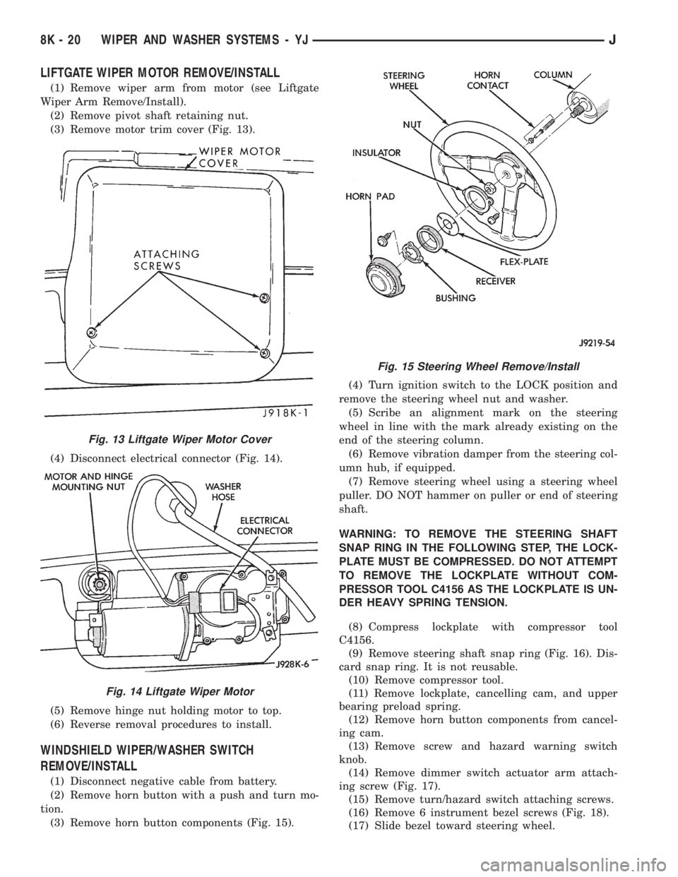
(3) Remove motor trim cover (Fig. 13).
(4) Disconnect electrical connector (Fig. 14).
(5) Remove hinge nut holding motor to top.
(6) Reverse removal procedures to install.
WINDSHIELD WIPER/WASHER SWITCH
REMOVE/INSTALL
(1) Disconnect negative cable from battery.
(2) Remove horn button with a push and turn mo-
tion.
(3) Remove horn button components (Fig. 15).(4) Turn ignition switch to the LOCK position and
remove the steering wheel nut and washer.
(5) Scribe an alignment mark on the steering
wheel in line with the mark already existing on the
end of the steering column.
(6) Remove vibration damper from the steering col-
umn hub, if equipped.
(7) Remove steering wheel using a steering wheel
puller. DO NOT hammer on puller or end of steering
shaft.
WARNING: TO REMOVE THE STEERING SHAFT
SNAP RING IN THE FOLLOWING STEP, THE LOCK-
PLATE MUST BE COMPRESSED. DO NOT ATTEMPT
TO REMOVE THE LOCKPLATE WITHOUT COM-
PRESSOR TOOL C4156 AS THE LOCKPLATE IS UN-
DER HEAVY SPRING TENSION.
(8) Compress lockplate with compressor tool
C4156.
(9) Remove steering shaft snap ring (Fig. 16). Dis-
card snap ring. It is not reusable.
(10) Remove compressor tool.
(11) Remove lockplate, cancelling cam, and upper
bearing preload spring.
(12) Remove horn button components from cancel-
ing cam.
(13) Remove screw and hazard warning switch
knob.
(14) Remove dimmer switch actuator arm attach-
ing screw (Fig. 17).
(15) Remove turn/hazard switch attaching screws.
(16) Remove 6 instrument bezel screws (Fig. 18).
(17) Slide bezel toward steering wheel.
Fig. 13 Liftgate Wiper Motor Cover
Fig. 14 Liftgate Wiper Motor
Fig. 15 Steering Wheel Remove/Install
8K - 20 WIPER AND WASHER SYSTEMS - YJJ
Page 443 of 2198
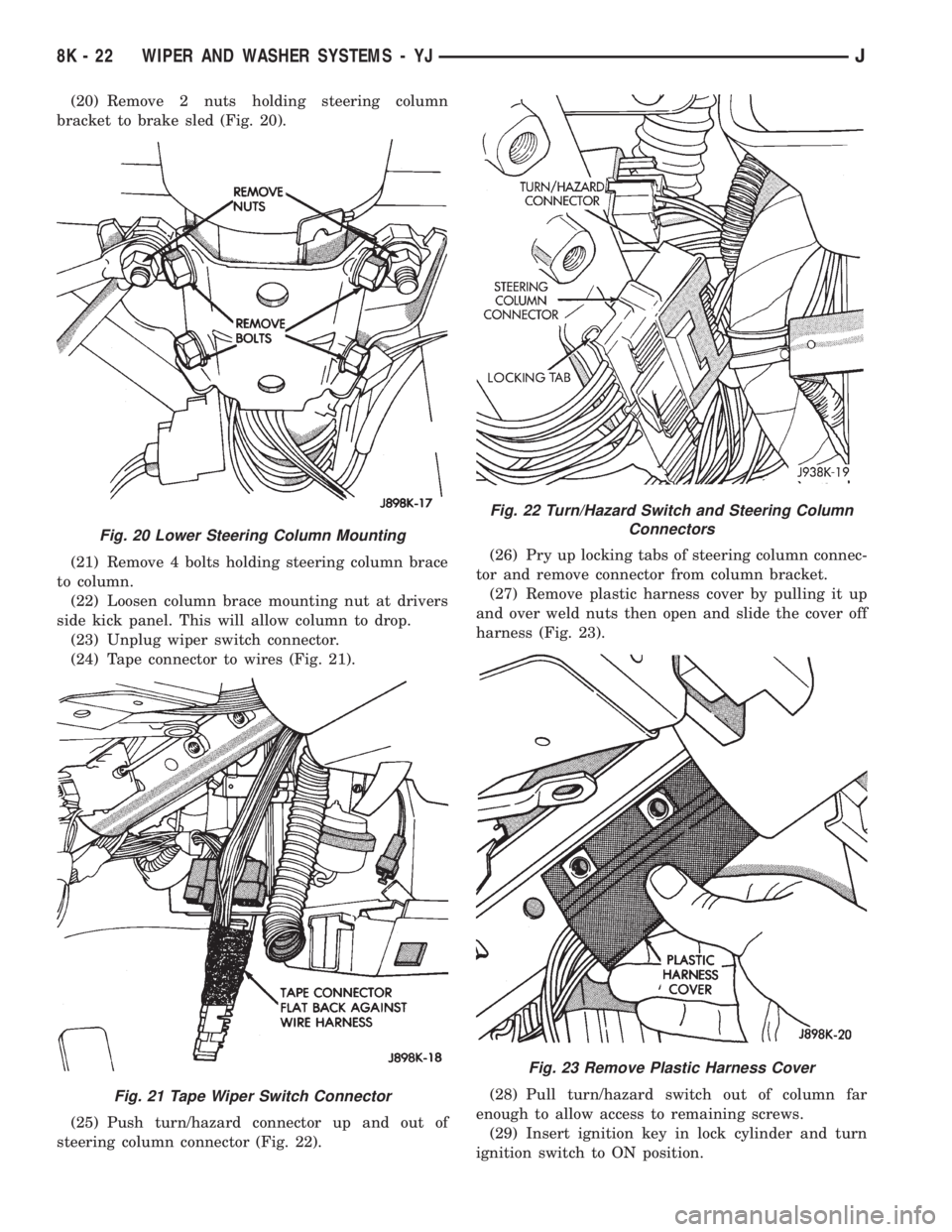
(20) Remove 2 nuts holding steering column
bracket to brake sled (Fig. 20).
(21) Remove 4 bolts holding steering column brace
to column.
(22) Loosen column brace mounting nut at drivers
side kick panel. This will allow column to drop.
(23) Unplug wiper switch connector.
(24) Tape connector to wires (Fig. 21).
(25) Push turn/hazard connector up and out of
steering column connector (Fig. 22).(26) Pry up locking tabs of steering column connec-
tor and remove connector from column bracket.
(27) Remove plastic harness cover by pulling it up
and over weld nuts then open and slide the cover off
harness (Fig. 23).
(28) Pull turn/hazard switch out of column far
enough to allow access to remaining screws.
(29) Insert ignition key in lock cylinder and turn
ignition switch to ON position.
Fig. 20 Lower Steering Column Mounting
Fig. 21 Tape Wiper Switch Connector
Fig. 22 Turn/Hazard Switch and Steering Column
Connectors
Fig. 23 Remove Plastic Harness Cover
8K - 22 WIPER AND WASHER SYSTEMS - YJJ
Page 444 of 2198
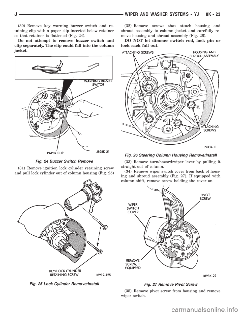
(30) Remove key warning buzzer switch and re-
taining clip with a paper clip inserted below retainer
so that retainer is flattened (Fig. 24).
Do not attempt to remove buzzer switch and
clip separately. The clip could fall into the column
jacket.
(31) Remove ignition lock cylinder retaining screw
and pull lock cylinder out of column housing (Fig. 25)(32) Remove screws that attach housing and
shroud assembly to column jacket and carefully re-
move housing and shroud assembly (Fig. 26).
DO NOT let dimmer switch rod, lock pin or
lock rack fall out.
(33) Remove turn/hazard/wiper lever by pulling it
straight out of column.
(34) Remove wiper switch cover from back of hous-
ing and shroud assembly (Fig. 27). If equipped with
column shift, remove screw holding the cover on.
(35) Remove pivot screw from housing and remove
wiper switch.
Fig. 24 Buzzer Switch Remove
Fig. 25 Lock Cylinder Remove/Install
Fig. 26 Steering Column Housing Remove/Install
Fig. 27 Remove Pivot Screw
JWIPER AND WASHER SYSTEMS - YJ 8K - 23
Page 445 of 2198
(36) Install a new switch and switch cover.
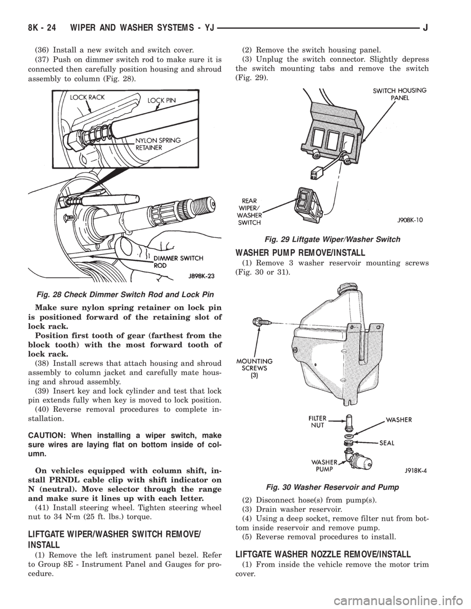
(37) Push on dimmer switch rod to make sure it is
connected then carefully position housing and shroud
assembly to column (Fig. 28).
Make sure nylon spring retainer on lock pin
is positioned forward of the retaining slot of
lock rack.
Position first tooth of gear (farthest from the
block tooth) with the most forward tooth of
lock rack.
(38) Install screws that attach housing and shroud
assembly to column jacket and carefully mate hous-
ing and shroud assembly.
(39) Insert key and lock cylinder and test that lock
pin extends fully when key is moved to lock position.
(40) Reverse removal procedures to complete in-
stallation.
CAUTION: When installing a wiper switch, make
sure wires are laying flat on bottom inside of col-
umn.
On vehicles equipped with column shift, in-
stall PRNDL cable clip with shift indicator on
N (neutral). Move selector through the range
and make sure it lines up with each letter.
(41) Install steering wheel. Tighten steering wheel
nut to 34 Nzm (25 ft. lbs.) torque.
LIFTGATE WIPER/WASHER SWITCH REMOVE/
INSTALL
(1) Remove the left instrument panel bezel. Refer
to Group 8E - Instrument Panel and Gauges for pro-
cedure.(2) Remove the switch housing panel.
(3) Unplug the switch connector. Slightly depress
the switch mounting tabs and remove the switch
(Fig. 29).
WASHER PUMP REMOVE/INSTALL
(1) Remove 3 washer reservoir mounting screws
(Fig. 30 or 31).
(2) Disconnect hose(s) from pump(s).
(3) Drain washer reservoir.
(4) Using a deep socket, remove filter nut from bot-
tom inside reservoir and remove pump.
(5) Reverse removal procedures to install.
LIFTGATE WASHER NOZZLE REMOVE/INSTALL
(1) From inside the vehicle remove the motor trim
cover.
Fig. 28 Check Dimmer Switch Rod and Lock Pin
Fig. 29 Liftgate Wiper/Washer Switch
Fig. 30 Washer Reservoir and Pump
8K - 24 WIPER AND WASHER SYSTEMS - YJJ
Page 451 of 2198
MULTI-FUNCTION SWITCH TESTING
PROCEDURESÐXJ
The multi-function switch contains electrical cir-
cuitry for:
²Headlamp Dimmer Switch.
²Passing Lights.
²Turn Signals.
²Hazard Warning.
²Windshield Wiper.
²Pulse Wiper.
²Windshield Washer.
This integrated switch is mounted to the left hand
side of the steering column. Should any function of
the switch fail, the entire switch must be replaced.
The multi-function switch also serves as a fog lamp
lock-out circuit. The circuit to the fog lamp switch is
completed only when the dimmer switch is in the low
beam position.
SWITCH TEST
(1) Disconnect battery negative cable.
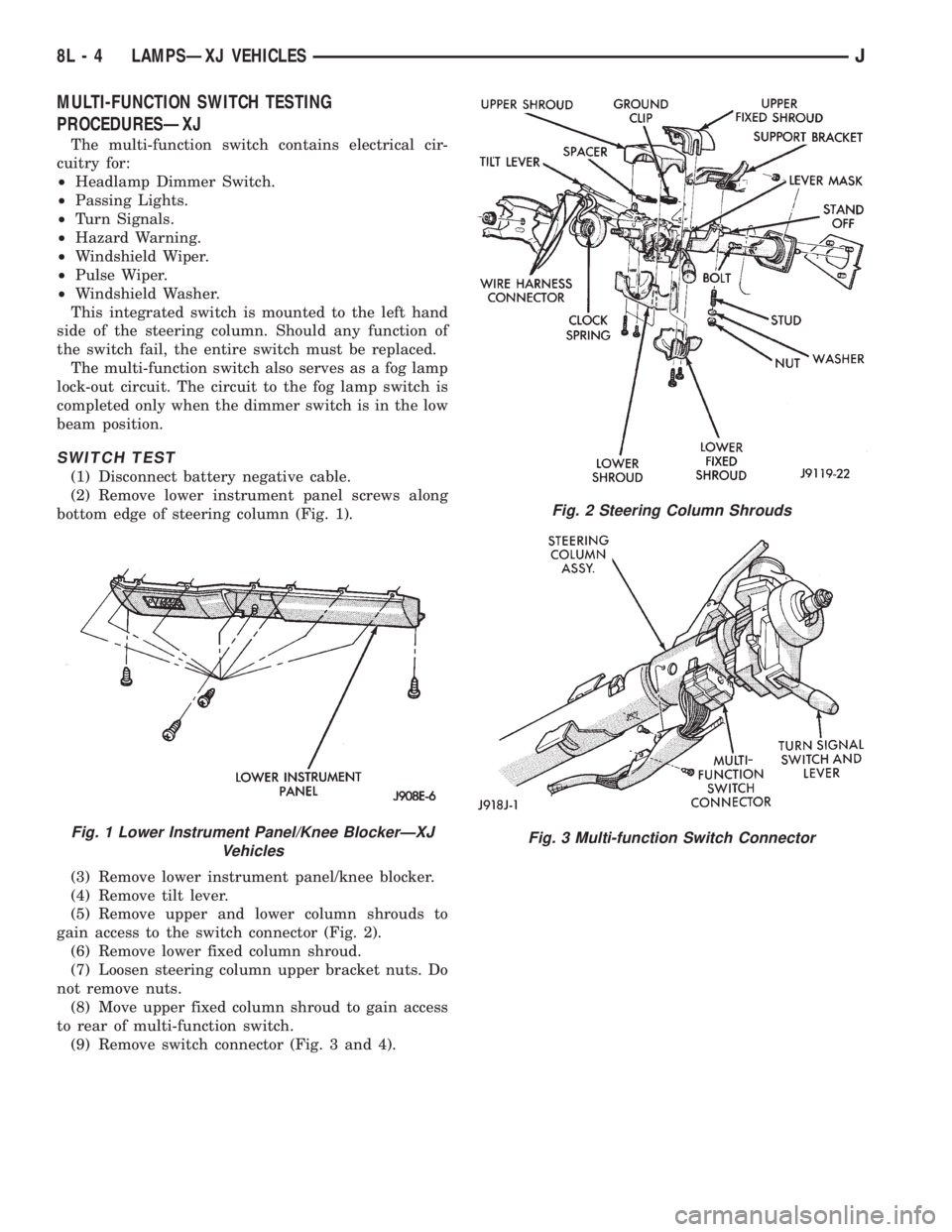
(2) Remove lower instrument panel screws along
bottom edge of steering column (Fig. 1).
(3) Remove lower instrument panel/knee blocker.
(4) Remove tilt lever.
(5) Remove upper and lower column shrouds to
gain access to the switch connector (Fig. 2).
(6) Remove lower fixed column shroud.
(7) Loosen steering column upper bracket nuts. Do
not remove nuts.
(8) Move upper fixed column shroud to gain access
to rear of multi-function switch.
(9) Remove switch connector (Fig. 3 and 4).
Fig. 1 Lower Instrument Panel/Knee BlockerÐXJ
Vehicles
Fig. 2 Steering Column Shrouds
Fig. 3 Multi-function Switch Connector
8L - 4 LAMPSÐXJ VEHICLESJ
Page 452 of 2198
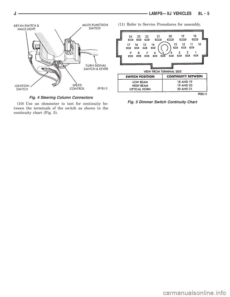
(10) Use an ohmmeter to test for continuity be-
tween the terminals of the switch as shown in the
continuity chart (Fig. 5).(11) Refer to Service Procedures for assembly.
Fig. 4 Steering Column Connectors
Fig. 5 Dimmer Switch Continuity Chart
JLAMPSÐXJ VEHICLES 8L - 5