1995 JEEP CHEROKEE steering
[x] Cancel search: steeringPage 378 of 2198
SERVICE PROCEDURES
CLUSTER ASSEMBLY REMOVE/INSTALL
MAIN CLUSTER
(1) Disconnect battery negative cable.
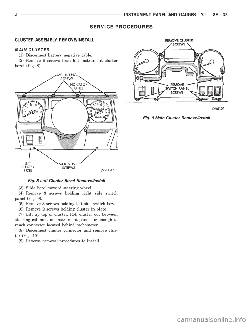
(2) Remove 6 screws from left instrument cluster
bezel (Fig. 8).
(3) Slide bezel toward steering wheel.
(4) Remove 3 screws holding right side switch
panel (Fig. 9).
(5) Remove 3 screws holding left side switch bezel.
(6) Remove 2 screws holding cluster in place.
(7) Lift up top of cluster. Roll cluster out between
steering column and instrument panel far enough to
reach connector located behind tachometer.
(8) Disconnect cluster connector and remove clus-
ter (Fig. 10).
(9) Reverse removal procedures to install.
Fig. 8 Left Cluster Bezel Remove/Install
Fig. 9 Main Cluster Remove/Install
JINSTRUMENT PANEL AND GAUGESÐYJ 8E - 35
Page 385 of 2198
HEADLAMP OR PANEL DIMMER SWITCH
REMOVE/INSTALL
(1) Disconnect battery negative cable.
(2) Remove 6 screws from left instrument cluster
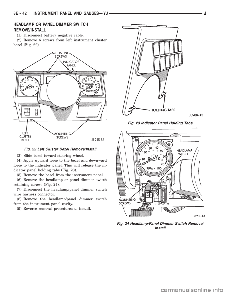
bezel (Fig. 22).
(3) Slide bezel toward steering wheel.
(4) Apply upward force to the bezel and downward
force to the indicator panel. This will release the in-
dicator panel holding tabs (Fig. 23).
(5) Remove the bezel from the instrument panel.
(6) Remove the headlamp or panel dimmer switch
retaining screws (Fig. 24).
(7) Disconnect the headlamp/panel dimmer switch
wire harness connector.
(8) Remove the headlamp/panel dimmer switch
from the instrument panel cavity.
(9) Reverse removal procedures to install.
Fig. 22 Left Cluster Bezel Remove/Install
Fig. 23 Indicator Panel Holding Tabs
Fig. 24 Headlamp/Panel Dimmer Switch Remove/
Install
8E - 42 INSTRUMENT PANEL AND GAUGESÐYJJ
Page 391 of 2198
RADIO ILLUMINATION RELAY
If the relay fails any one of Relay Tests, it is faulty
and should be replaced. If the relay passes the Relay
Tests, proceed to the Relay Circuit Tests.
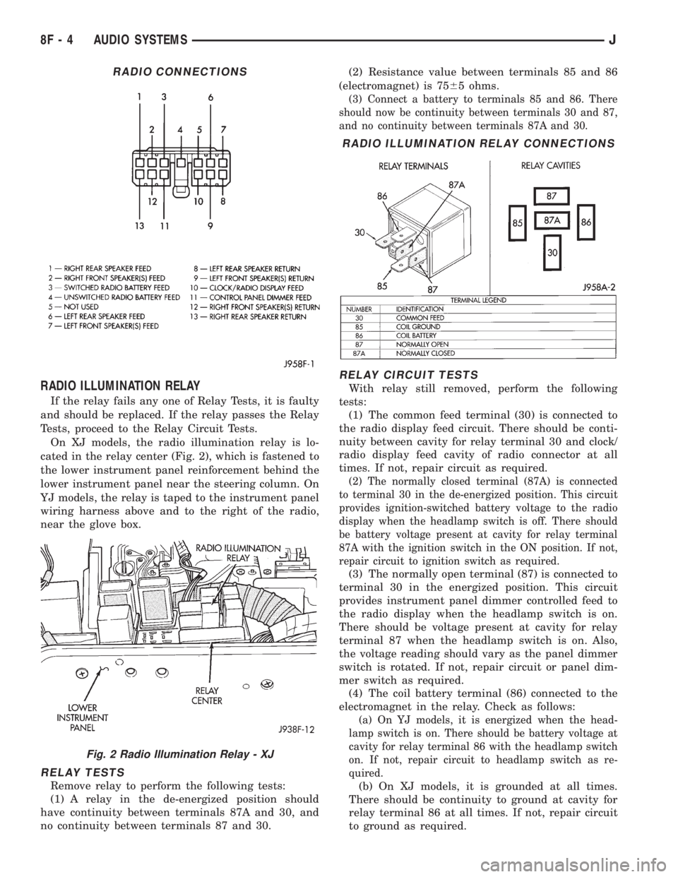
On XJ models, the radio illumination relay is lo-
cated in the relay center (Fig. 2), which is fastened to
the lower instrument panel reinforcement behind the
lower instrument panel near the steering column. On
YJ models, the relay is taped to the instrument panel
wiring harness above and to the right of the radio,
near the glove box.
RELAY TESTS
Remove relay to perform the following tests:
(1) A relay in the de-energized position should
have continuity between terminals 87A and 30, and
no continuity between terminals 87 and 30.(2) Resistance value between terminals 85 and 86
(electromagnet) is 7565 ohms.
(3) Connect a battery to terminals 85 and 86. There
should now be continuity between terminals 30 and 87,
and no continuity between terminals 87A and 30.
RELAY CIRCUIT TESTS
With relay still removed, perform the following
tests:
(1) The common feed terminal (30) is connected to
the radio display feed circuit. There should be conti-
nuity between cavity for relay terminal 30 and clock/
radio display feed cavity of radio connector at all
times. If not, repair circuit as required.
(2) The normally closed terminal (87A) is connected
to terminal 30 in the de-energized position. This circuit
provides ignition-switched battery voltage to the radio
display when the headlamp switch is off. There should
be battery voltage present at cavity for relay terminal
87A with the ignition switch in the ON position. If not,
repair circuit to ignition switch as required.
(3) The normally open terminal (87) is connected to
terminal 30 in the energized position. This circuit
provides instrument panel dimmer controlled feed to
the radio display when the headlamp switch is on.
There should be voltage present at cavity for relay
terminal 87 when the headlamp switch is on. Also,
the voltage reading should vary as the panel dimmer
switch is rotated. If not, repair circuit or panel dim-
mer switch as required.
(4) The coil battery terminal (86) connected to the
electromagnet in the relay. Check as follows:
(a) On YJ models, it is energized when the head-
lamp switch is on. There should be battery voltage at
cavity for relay terminal 86 with the headlamp switch
on. If not, repair circuit to headlamp switch as re-
quired.
(b) On XJ models, it is grounded at all times.
There should be continuity to ground at cavity for
relay terminal 86 at all times. If not, repair circuit
to ground as required.
RADIO CONNECTIONS
Fig. 2 Radio Illumination Relay - XJ
RADIO ILLUMINATION RELAY CONNECTIONS
8F - 4 AUDIO SYSTEMSJ
Page 393 of 2198
SERVICE PROCEDURES
RADIO REMOVE/INSTALL - XJ
(1) Disconnect battery negative cable.
(2) Remove upper and lower steering column
shrouds and steering column to instrument panel be-
zel gap hider. If equipped with tilt steering, apply
tape to tilt mechanism on top of steering column to
protect instrument panel bezel from damage during
removal.
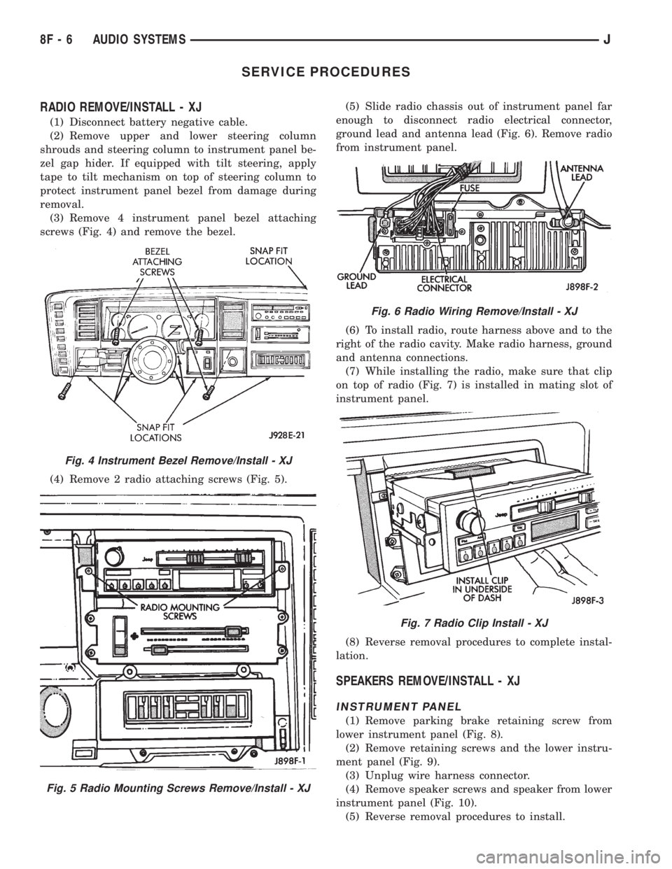
(3) Remove 4 instrument panel bezel attaching
screws (Fig. 4) and remove the bezel.
(4) Remove 2 radio attaching screws (Fig. 5).(5) Slide radio chassis out of instrument panel far
enough to disconnect radio electrical connector,
ground lead and antenna lead (Fig. 6). Remove radio
from instrument panel.
(6) To install radio, route harness above and to the
right of the radio cavity. Make radio harness, ground
and antenna connections.
(7) While installing the radio, make sure that clip
on top of radio (Fig. 7) is installed in mating slot of
instrument panel.
(8) Reverse removal procedures to complete instal-
lation.
SPEAKERS REMOVE/INSTALL - XJ
INSTRUMENT PANEL
(1) Remove parking brake retaining screw from
lower instrument panel (Fig. 8).
(2) Remove retaining screws and the lower instru-
ment panel (Fig. 9).
(3) Unplug wire harness connector.
(4) Remove speaker screws and speaker from lower
instrument panel (Fig. 10).
(5) Reverse removal procedures to install.
Fig. 4 Instrument Bezel Remove/Install - XJ
Fig. 5 Radio Mounting Screws Remove/Install - XJ
Fig. 6 Radio Wiring Remove/Install - XJ
Fig. 7 Radio Clip Install - XJ
8F - 6 AUDIO SYSTEMSJ
Page 398 of 2198
HORNS
CONTENTS
page page
DIAGNOSIS............................. 2
GENERAL INFORMATION.................. 1SERVICE PROCEDURES................... 3
SPECIFICATIONS......................... 5
GENERAL INFORMATION
Following are general descriptions of the major
components in the XJ (Cherokee)/YJ (Wrangler) horn
systems. Refer to Group 8W - Wiring Diagrams for
complete circuit descriptions and diagrams.
HORN SWITCH
XJ
Two horn switches are installed in the steering
wheel, one on each side of the center-mounted driv-
er's airbag module. When either switch is depressed
it completes a circuit to ground for the coil side of the
horn relay. The steering wheel and steering column
must be properly grounded for the horn switches to
function. The horn switches are only serviced as a set
with their wiring. If either switch should fail, both
switches must be replaced.
YJ
A single switch is installed in the center of the
steering wheel, directly under the horn button. When
the horn button is depressed the switch completes a
circuit to ground for the coil side of the horn relay.
The steering wheel and steering column must be
properly grounded for the horn switch to function.
The horn switch is available for service.
HORN RELAY
On XJ models, the horn relay is a mini-relay in-
stalled in the relay center, which is mounted to the
lower instrument panel reinforcement inboard of thesteering column. On YJ models, the horn relay is a
ISO relay installed in the Power Distribution Center
(PDC) near the battery tray. Refer to underside of
PDC cover for relay identification.
One side of the horn relay electromagnetic coil re-
ceives battery voltage at all times. When a horn
switch is depressed, the other side of the relay coil is
grounded. The energized relay coil causes the nor-
mally open relay contacts to close, providing battery
voltage to the horn.
If a problem is encountered with a continuously
sounding horn, it can usually be quickly resolved by
removing the horn relay until further diagnosis is
completed.
HORNS
On YJ models, a standard single, low-note, dia-
phragm-type horn is mounted and grounded to the
left inner fender shield under the hood. Dual horns
are standard equipment on XJ models. The high-note
diaphragm-type horn is mounted and grounded to
the left radiator closure panel brace behind the front
bumper. The low-note diaphragm-type horn is con-
nected in parallel with the high-note horn and is
mounted and grounded to the right radiator closure
panel brace behind the front bumper.
On XJ models, a cadmium-plated screw is
used to attach the horns to the body. Do not
substitute other types of screws as they may be-
come corroded and cause a loss of ground.
JHORNS 8G - 1
Page 399 of 2198
DIAGNOSIS
WARNING: ON VEHICLES EQUIPPED WITH AN AIR-
BAG, REFER TO GROUP 8M - RESTRAINT SYS-
TEMS BEFORE ATTEMPTING STEERING WHEEL
COMPONENT DIAGNOSIS OR SERVICE. FAILURE
TO TAKE PROPER PRECAUTIONS COULD RESULT
IN ACCIDENTAL AIRBAG DEPLOYMENT AND POS-
SIBLE PERSONAL INJURY.
(1) Inspect fuses (F8 and F16 in PDC on YJ)(11 in
fuseblock module and F14 in PDC on XJ). Replace
fuses, as required.
(2) Remove the horn relay (in the PDC on YJ)(in
the relay center on XJ). See Horn Relay Connec-
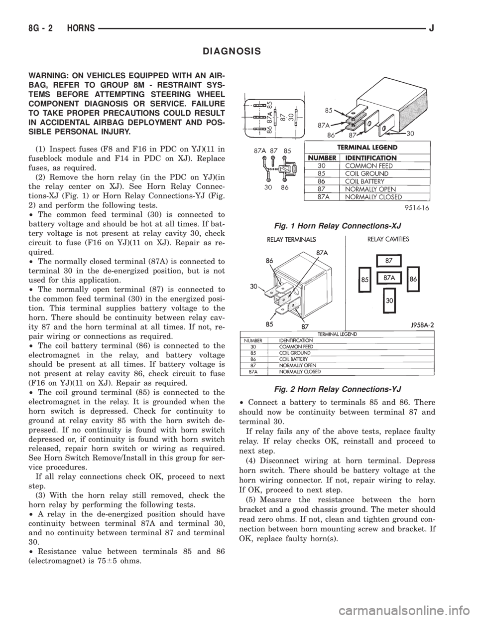
tions-XJ (Fig. 1) or Horn Relay Connections-YJ (Fig.
2) and perform the following tests.
²The common feed terminal (30) is connected to
battery voltage and should be hot at all times. If bat-
tery voltage is not present at relay cavity 30, check
circuit to fuse (F16 on YJ)(11 on XJ). Repair as re-
quired.
²The normally closed terminal (87A) is connected to
terminal 30 in the de-energized position, but is not
used for this application.
²The normally open terminal (87) is connected to
the common feed terminal (30) in the energized posi-
tion. This terminal supplies battery voltage to the
horn. There should be continuity between relay cav-
ity 87 and the horn terminal at all times. If not, re-
pair wiring or connections as required.
²The coil battery terminal (86) is connected to the
electromagnet in the relay, and battery voltage
should be present at all times. If battery voltage is
not present at relay cavity 86, check circuit to fuse
(F16 on YJ)(11 on XJ). Repair as required.
²The coil ground terminal (85) is connected to the
electromagnet in the relay. It is grounded when the
horn switch is depressed. Check for continuity to
ground at relay cavity 85 with the horn switch de-
pressed. If no continuity is found with horn switch
depressed or, if continuity is found with horn switch
released, repair horn switch or wiring as required.
See Horn Switch Remove/Install in this group for ser-
vice procedures.
If all relay connections check OK, proceed to next
step.
(3) With the horn relay still removed, check the
horn relay by performing the following tests.
²A relay in the de-energized position should have
continuity between terminal 87A and terminal 30,
and no continuity between terminal 87 and terminal
30.
²Resistance value between terminals 85 and 86
(electromagnet) is 7565 ohms.²Connect a battery to terminals 85 and 86. There
should now be continuity between terminal 87 and
terminal 30.
If relay fails any of the above tests, replace faulty
relay. If relay checks OK, reinstall and proceed to
next step.
(4) Disconnect wiring at horn terminal. Depress
horn switch. There should be battery voltage at the
horn wiring connector. If not, repair wiring to relay.
If OK, proceed to next step.
(5) Measure the resistance between the horn
bracket and a good chassis ground. The meter should
read zero ohms. If not, clean and tighten ground con-
nection between horn mounting screw and bracket. If
OK, replace faulty horn(s).
Fig. 1 Horn Relay Connections-XJ
Fig. 2 Horn Relay Connections-YJ
8G - 2 HORNSJ
Page 400 of 2198
SERVICE PROCEDURES
HORN REMOVE/INSTALL
XJ
(1) Raise and support the vehicle.
(2) Remove the front underbody splash shield.
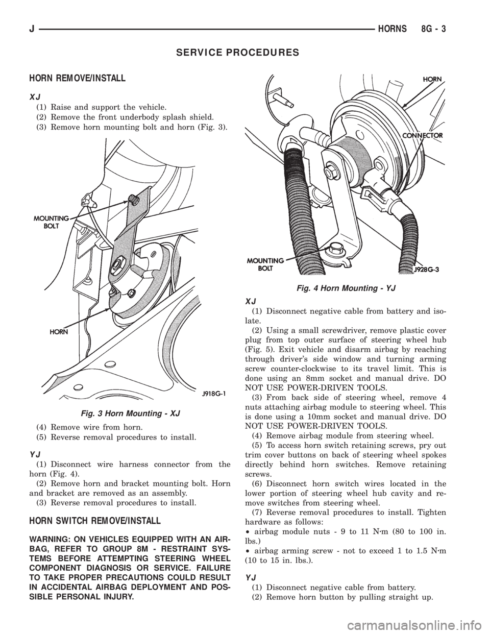
(3) Remove horn mounting bolt and horn (Fig. 3).
(4) Remove wire from horn.
(5) Reverse removal procedures to install.
YJ
(1) Disconnect wire harness connector from the
horn (Fig. 4).
(2) Remove horn and bracket mounting bolt. Horn
and bracket are removed as an assembly.
(3) Reverse removal procedures to install.
HORN SWITCH REMOVE/INSTALL
WARNING: ON VEHICLES EQUIPPED WITH AN AIR-
BAG, REFER TO GROUP 8M - RESTRAINT SYS-
TEMS BEFORE ATTEMPTING STEERING WHEEL
COMPONENT DIAGNOSIS OR SERVICE. FAILURE
TO TAKE PROPER PRECAUTIONS COULD RESULT
IN ACCIDENTAL AIRBAG DEPLOYMENT AND POS-
SIBLE PERSONAL INJURY.
XJ
(1) Disconnect negative cable from battery and iso-
late.
(2) Using a small screwdriver, remove plastic cover
plug from top outer surface of steering wheel hub
(Fig. 5). Exit vehicle and disarm airbag by reaching
through driver's side window and turning arming
screw counter-clockwise to its travel limit. This is
done using an 8mm socket and manual drive. DO
NOT USE POWER-DRIVEN TOOLS.
(3) From back side of steering wheel, remove 4
nuts attaching airbag module to steering wheel. This
is done using a 10mm socket and manual drive. DO
NOT USE POWER-DRIVEN TOOLS.
(4) Remove airbag module from steering wheel.
(5) To access horn switch retaining screws, pry out
trim cover buttons on back of steering wheel spokes
directly behind horn switches. Remove retaining
screws.
(6) Disconnect horn switch wires located in the
lower portion of steering wheel hub cavity and re-
move switches from steering wheel.
(7) Reverse removal procedures to install. Tighten
hardware as follows:
²airbag module nuts-9to11Nzm (80 to 100 in.
lbs.)
²airbag arming screw - not to exceed 1 to 1.5 Nzm
(10 to 15 in. lbs.).
YJ
(1) Disconnect negative cable from battery.
(2) Remove horn button by pulling straight up.
Fig. 3 Horn Mounting - XJ
Fig. 4 Horn Mounting - YJ
JHORNS 8G - 3
Page 401 of 2198
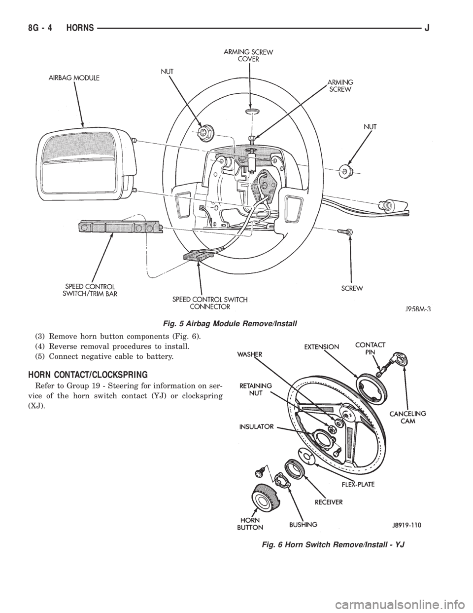
(3) Remove horn button components (Fig. 6).
(4) Reverse removal procedures to install.
(5) Connect negative cable to battery.
HORN CONTACT/CLOCKSPRING
Refer to Group 19 - Steering for information on ser-
vice of the horn switch contact (YJ) or clockspring
(XJ).
Fig. 5 Airbag Module Remove/Install
Fig. 6 Horn Switch Remove/Install - YJ
8G - 4 HORNSJ