1995 JEEP CHEROKEE steering
[x] Cancel search: steeringPage 182 of 2198
DISC BRAKES
INDEX
page page
Caliper Assembly......................... 50
Caliper Cleaning and Inspection.............. 50
Caliper Disassembly....................... 48
Caliper Installation........................ 51
Caliper Operation and Wear Compensation...... 45
Caliper Removal.......................... 48
Disc Brake Rotor Refinishing................. 53
Disc Brake Rotor Runout.................... 52Disc Brake Rotor Thickness................. 52
Disc Brake Rotor Thickness Variation.......... 52
Disc Brakeshoe Installation.................. 47
Disc Brakeshoe Removal................... 46
General Information....................... 45
Rotor Installation.......................... 51
Rotor Removal........................... 51
Wheel Nut Tightening...................... 54
GENERAL INFORMATION
Jeep XJ/YJ models are equipped with single piston,
floating-type disc brake calipers. Ventilated, cast ro-
tors are used for all applications.
The disc brake calipers are supported in mounting
arms that are an integral part of the steering
knuckle. The calipers slide on mounting bolts that
also attach the calipers to the steering knuckle.
CALIPER OPERATION AND WEAR COMPENSATION
Caliper Operation
The significant feature of single piston caliper op-
eration is that the calipers are free to slide laterally
on the mounting bolts. It is the freedom of lateral
movement that allows continuous compensation for
lining wear.
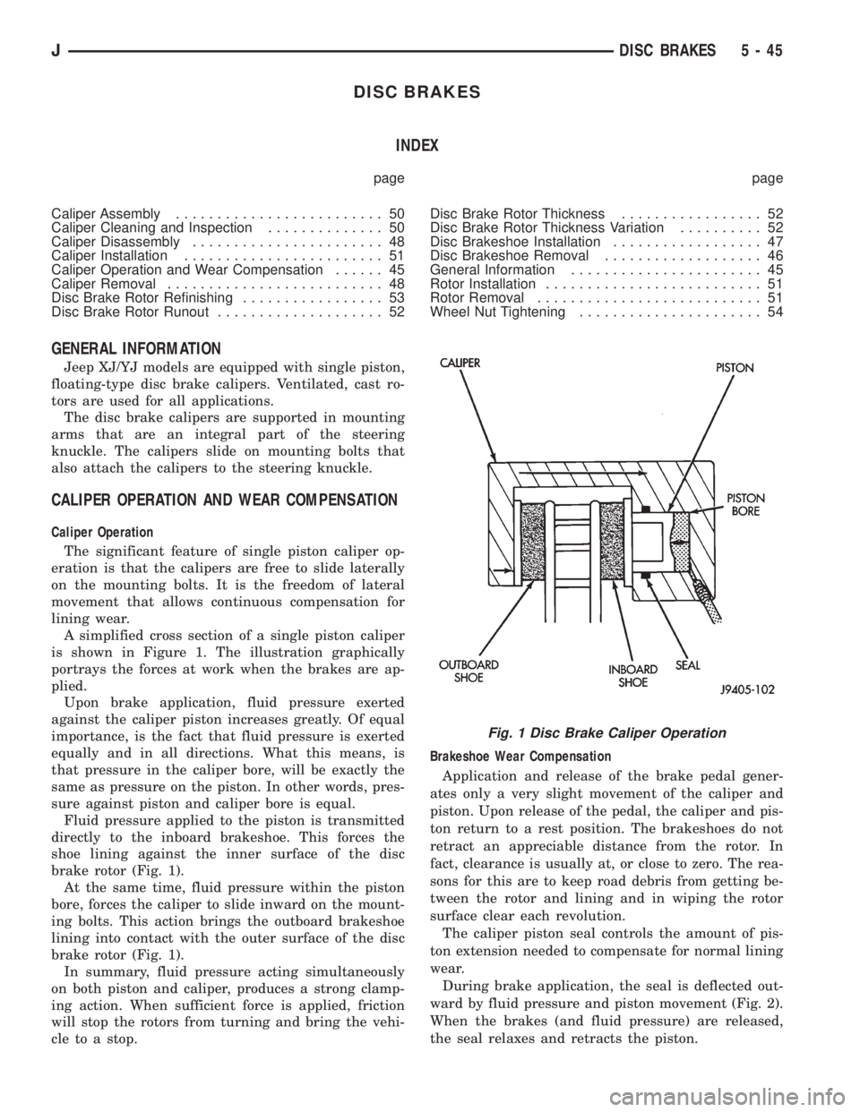
A simplified cross section of a single piston caliper
is shown in Figure 1. The illustration graphically
portrays the forces at work when the brakes are ap-
plied.
Upon brake application, fluid pressure exerted
against the caliper piston increases greatly. Of equal
importance, is the fact that fluid pressure is exerted
equally and in all directions. What this means, is
that pressure in the caliper bore, will be exactly the
same as pressure on the piston. In other words, pres-
sure against piston and caliper bore is equal.
Fluid pressure applied to the piston is transmitted
directly to the inboard brakeshoe. This forces the
shoe lining against the inner surface of the disc
brake rotor (Fig. 1).
At the same time, fluid pressure within the piston
bore, forces the caliper to slide inward on the mount-
ing bolts. This action brings the outboard brakeshoe
lining into contact with the outer surface of the disc
brake rotor (Fig. 1).
In summary, fluid pressure acting simultaneously
on both piston and caliper, produces a strong clamp-
ing action. When sufficient force is applied, friction
will stop the rotors from turning and bring the vehi-
cle to a stop.Brakeshoe Wear Compensation
Application and release of the brake pedal gener-
ates only a very slight movement of the caliper and
piston. Upon release of the pedal, the caliper and pis-
ton return to a rest position. The brakeshoes do not
retract an appreciable distance from the rotor. In
fact, clearance is usually at, or close to zero. The rea-
sons for this are to keep road debris from getting be-
tween the rotor and lining and in wiping the rotor
surface clear each revolution.
The caliper piston seal controls the amount of pis-
ton extension needed to compensate for normal lining
wear.
During brake application, the seal is deflected out-
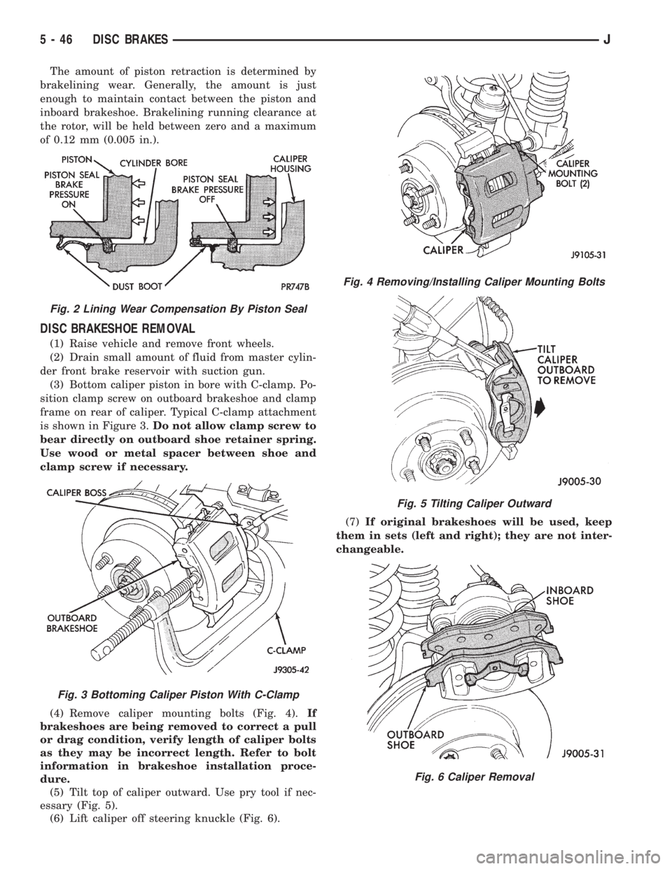
ward by fluid pressure and piston movement (Fig. 2).
When the brakes (and fluid pressure) are released,
the seal relaxes and retracts the piston.
Fig. 1 Disc Brake Caliper Operation
JDISC BRAKES 5 - 45
Page 183 of 2198
The amount of piston retraction is determined by
brakelining wear. Generally, the amount is just
enough to maintain contact between the piston and
inboard brakeshoe. Brakelining running clearance at
the rotor, will be held between zero and a maximum
of 0.12 mm (0.005 in.).
DISC BRAKESHOE REMOVAL
(1) Raise vehicle and remove front wheels.
(2) Drain small amount of fluid from master cylin-
der front brake reservoir with suction gun.
(3) Bottom caliper piston in bore with C-clamp. Po-
sition clamp screw on outboard brakeshoe and clamp
frame on rear of caliper. Typical C-clamp attachment
is shown in Figure 3.Do not allow clamp screw to
bear directly on outboard shoe retainer spring.
Use wood or metal spacer between shoe and
clamp screw if necessary.
(4) Remove caliper mounting bolts (Fig. 4).If
brakeshoes are being removed to correct a pull
or drag condition, verify length of caliper bolts
as they may be incorrect length. Refer to bolt
information in brakeshoe installation proce-
dure.
(5) Tilt top of caliper outward. Use pry tool if nec-
essary (Fig. 5).
(6) Lift caliper off steering knuckle (Fig. 6).(7)If original brakeshoes will be used, keep
them in sets (left and right); they are not inter-
changeable.
Fig. 2 Lining Wear Compensation By Piston Seal
Fig. 3 Bottoming Caliper Piston With C-Clamp
Fig. 4 Removing/Installing Caliper Mounting Bolts
Fig. 5 Tilting Caliper Outward
Fig. 6 Caliper Removal
5 - 46 DISC BRAKESJ
Page 184 of 2198
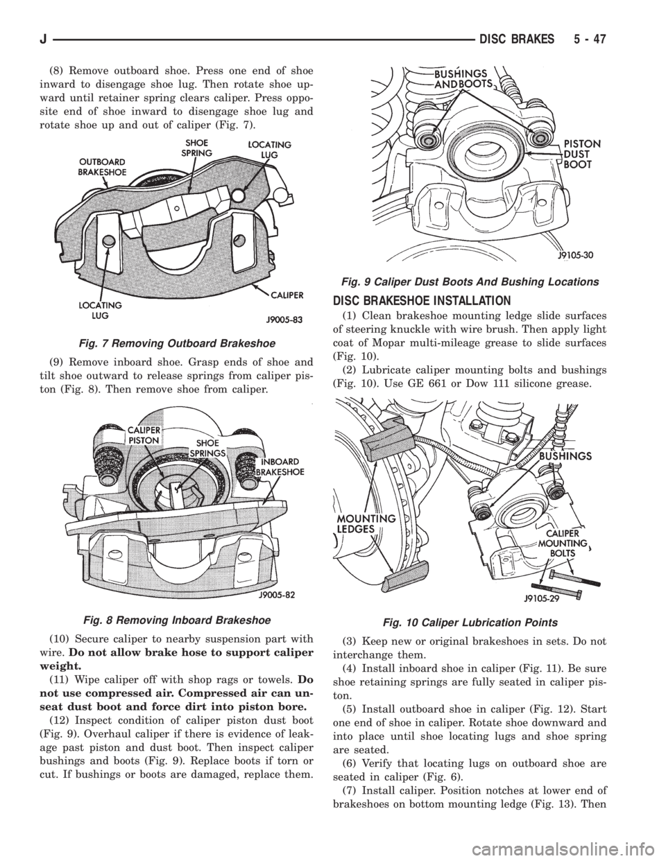
(8) Remove outboard shoe. Press one end of shoe
inward to disengage shoe lug. Then rotate shoe up-
ward until retainer spring clears caliper. Press oppo-
site end of shoe inward to disengage shoe lug and
rotate shoe up and out of caliper (Fig. 7).
(9) Remove inboard shoe. Grasp ends of shoe and
tilt shoe outward to release springs from caliper pis-
ton (Fig. 8). Then remove shoe from caliper.
(10) Secure caliper to nearby suspension part with
wire.Do not allow brake hose to support caliper
weight.
(11) Wipe caliper off with shop rags or towels.Do
not use compressed air. Compressed air can un-
seat dust boot and force dirt into piston bore.
(12) Inspect condition of caliper piston dust boot
(Fig. 9). Overhaul caliper if there is evidence of leak-
age past piston and dust boot. Then inspect caliper
bushings and boots (Fig. 9). Replace boots if torn or
cut. If bushings or boots are damaged, replace them.
DISC BRAKESHOE INSTALLATION
(1) Clean brakeshoe mounting ledge slide surfaces
of steering knuckle with wire brush. Then apply light
coat of Mopar multi-mileage grease to slide surfaces
(Fig. 10).
(2) Lubricate caliper mounting bolts and bushings
(Fig. 10). Use GE 661 or Dow 111 silicone grease.
(3) Keep new or original brakeshoes in sets. Do not
interchange them.
(4) Install inboard shoe in caliper (Fig. 11). Be sure
shoe retaining springs are fully seated in caliper pis-
ton.
(5) Install outboard shoe in caliper (Fig. 12). Start
one end of shoe in caliper. Rotate shoe downward and
into place until shoe locating lugs and shoe spring
are seated.
(6) Verify that locating lugs on outboard shoe are
seated in caliper (Fig. 6).
(7) Install caliper. Position notches at lower end of
brakeshoes on bottom mounting ledge (Fig. 13). Then
Fig. 7 Removing Outboard Brakeshoe
Fig. 8 Removing Inboard Brakeshoe
Fig. 9 Caliper Dust Boots And Bushing Locations
Fig. 10 Caliper Lubrication Points
JDISC BRAKES 5 - 47
Page 185 of 2198
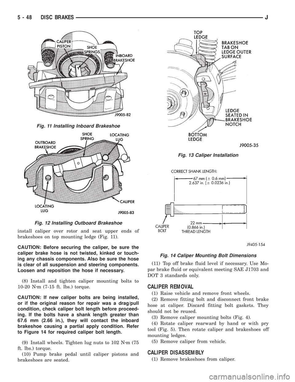
install caliper over rotor and seat upper ends of
brakeshoes on top mounting ledge (Fig. 11).
CAUTION: Before securing the caliper, be sure the
caliper brake hose is not twisted, kinked or touch-
ing any chassis components. Also be sure the hose
is clear of all suspension and steering components.
Loosen and reposition the hose if necessary.
(8) Install and tighten caliper mounting bolts to
10-20 Nzm (7-15 ft. lbs.) torque.
CAUTION: If new caliper bolts are being installed,
or if the original reason for repair was a drag/pull
condition, check caliper bolt length before proceed-
ing. If the bolts have a shank length greater than
67.6 mm (2.66 in.), they will contact the inboard
brakeshoe causing a partial apply condition. Refer
to Figure 14 for required caliper bolt length.
(9) Install wheels. Tighten lug nuts to 102 Nzm (75
ft. lbs.) torque.
(10) Pump brake pedal until caliper pistons and
brakeshoes are seated.(11) Top off brake fluid level if necessary. Use Mo-
par brake fluid or equivalent meeting SAE J1703 and
DOT 3 standards only.
CALIPER REMOVAL
(1) Raise vehicle and remove front wheels.
(2) Remove fitting bolt and disconnect front brake
hose at caliper. Discard fitting bolt gaskets. They
should not be reused.
(3) Remove caliper mounting bolts (Fig. 4).
(4) Rotate caliper rearward by hand or with pry
tool (Fig. 5). Then rotate caliper and brakeshoes off
mounting ledges.
(5) Remove caliper from vehicle.
CALIPER DISASSEMBLY
(1) Remove brakeshoes from caliper.
Fig. 11 Installing Inboard Brakeshoe
Fig. 12 Installing Outboard Brakeshoe
Fig. 13 Caliper Installation
Fig. 14 Caliper Mounting Bolt Dimensions
5 - 48 DISC BRAKESJ
Page 188 of 2198
CALIPER INSTALLATION
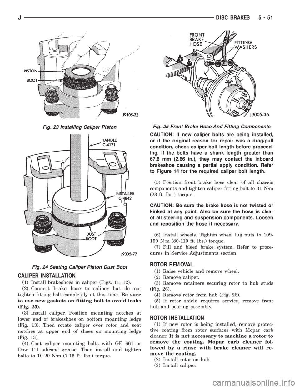
(1) Install brakeshoes in caliper (Figs. 11, 12).
(2) Connect brake hose to caliper but do not
tighten fitting bolt completely at this time.Be sure
to use new gaskets on fitting bolt to avoid leaks
(Fig. 25).
(3) Install caliper. Position mounting notches at
lower end of brakeshoes on bottom mounting ledge
(Fig. 13). Then rotate caliper over rotor and seat
notches at upper end of shoes on mounting ledge
(Fig. 13).
(4) Coat caliper mounting bolts with GE 661 or
Dow 111 silicone grease. Then install and tighten
bolts to 10-20 Nzm (7-15 ft. lbs.) torque.CAUTION: If new caliper bolts are being installed,
or if the original reason for repair was a drag/pull
condition, check caliper bolt length before proceed-
ing. If the bolts have a shank length greater than
67.6 mm (2.66 in.), they may contact the inboard
brakeshoe causing a partial apply condition. Refer
to Figure 14 for the required caliper bolt length.
(5) Position front brake hose clear of all chassis
components and tighten caliper fitting bolt to 31 Nzm
(23 ft. lbs.) torque.
CAUTION: Be sure the brake hose is not twisted or
kinked at any point. Also be sure the hose is clear
of all steering and suspension components. Loosen
and reposition the hose if necessary.
(6) Install wheels. Tighten wheel lug nuts to 109-
150 Nzm (80-110 ft. lbs.) torque.
(7) Fill and bleed brake system. Refer to proce-
dures in Service Adjustments section.
ROTOR REMOVAL
(1) Raise vehicle and remove wheel.
(2) Remove caliper.
(3) Remove retainers securing rotor to hub studs
(Fig. 26).
(4) Remove rotor from hub (Fig. 26).
(5) If rotor shield requires service, remove front
hub and bearing assembly.
ROTOR INSTALLATION
(1) If new rotor is being installed, remove protec-
tive coating from rotor surfaces with Mopar carb
cleaner.It is not necessary to machine a rotor to
remove the coating. Mopar carb cleaner fol-
lowed by a rinse with brake cleaner will re-
move the coating.
(2) Install rotor on hub.
(3) Install caliper.
Fig. 23 Installing Caliper Piston
Fig. 24 Seating Caliper Piston Dust Boot
Fig. 25 Front Brake Hose And Fitting Components
JDISC BRAKES 5 - 51
Page 240 of 2198
The engine accessory drive belt must be removed
prior to removing the fan (if installed at pump) or
fan pulley.
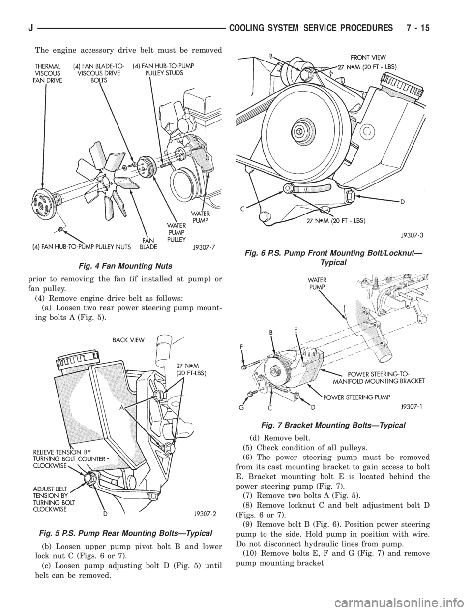
(4) Remove engine drive belt as follows:
(a) Loosen two rear power steering pump mount-
ing bolts A (Fig. 5).
(b) Loosen upper pump pivot bolt B and lower
lock nut C (Figs. 6 or 7).
(c) Loosen pump adjusting bolt D (Fig. 5) until
belt can be removed.(d) Remove belt.
(5) Check condition of all pulleys.
(6) The power steering pump must be removed
from its cast mounting bracket to gain access to bolt
E. Bracket mounting bolt E is located behind the
power steering pump (Fig. 7).
(7) Remove two bolts A (Fig. 5).
(8) Remove locknut C and belt adjustment bolt D
(Figs. 6 or 7).
(9) Remove bolt B (Fig. 6). Position power steering
pump to the side. Hold pump in position with wire.
Do not disconnect hydraulic lines from pump.
(10) Remove bolts E, F and G (Fig. 7) and remove
pump mounting bracket.
Fig. 4 Fan Mounting Nuts
Fig. 5 P.S. Pump Rear Mounting BoltsÐTypical
Fig. 6 P.S. Pump Front Mounting Bolt/LocknutÐ
Typical
Fig. 7 Bracket Mounting BoltsÐTypical
JCOOLING SYSTEM SERVICE PROCEDURES 7 - 15
Page 242 of 2198
INSTALLATIONÐALL MODELS
(1) If pump is being replaced, install the heater
hose fitting to the pump. Use a sealant on the fitting
such as MoparŸ Thread Sealant With Teflon. Refer
to the directions on the package.
(2) Clean the gasket mating surfaces. If the origi-
nal pump is used, remove any deposits or other for-
eign material. Inspect the cylinder block and water
pump mating surfaces for erosion or damage from
cavitation.
(3) Install the gasket and water pump. The silicone
bead on the gasket should be facing the water pump.
Also, the gasket is installed dry. Tighten mounting
bolts to 30 Nzm (22 ft. lbs.) torque. Rotate the shaft
by hand to be sure it turns freely.
(4) Connect the radiator and heater hoses to the
water pump.
(5) Position water pump pulley to water pump hub.
(6) If equipped with a water pump mounted fan,
install fan and four nuts to water pump hub. If not
equipped with a water pump mounted fan, install
four pump hub bolts. Tighten bolts (or nuts) to 27
Nzm (20 ft. lbs.) torque.
(7) Position power steering pump bracket to en-
gine. Install bolts E, F and G (Fig. 7). Tighten bolts F
andGto38Nzm (28 ft. lbs.) torque. Tighten bolt E to
27 Nzm (20 ft. lbs.) torque.
(8) Position power steering pump to mounting
bracket. Install pivot bolt B (Fig. 6) finger tight. In-
stall locknut C and adjustment bolt D (Figs. 6 or 7)
finger tight.
(9) Install two adjustment bolts A (Fig. 6) finger
tight.
(10) Install idler pulley.
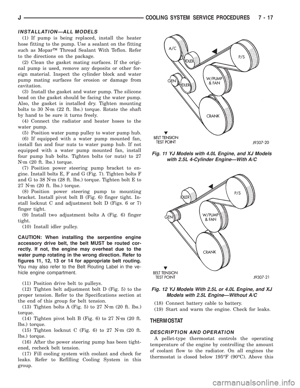
CAUTION: When installing the serpentine engine
accessory drive belt, the belt MUST be routed cor-
rectly. If not, the engine may overheat due to the
water pump rotating in the wrong direction. Refer to
figures 11, 12, 13 or 14 for appropriate belt routing.
You may also refer to the Belt Routing Label in the ve-
hicle engine compartment.
(11) Position drive belt to pulleys.
(12) Tighten belt adjustment bolt D (Fig. 5) to the
proper tension. Refer to the Specifications section at
the end of this group for belt tension.
(13) Tighten bolts A (Fig. 5) to 27 Nzm (20 ft. lbs.)
torque.
(14) Tighten pivot bolt B (Fig. 6) to 27 Nzm (20 ft.
lbs.) torque.
(15) Tighten locknut C (Fig. 6) to 27 Nzm (20 ft.
lbs.) torque.
(16) After the power steering pump has been tight-
ened, recheck belt tension.
(17) Fill cooling system with coolant and check for
leaks. Refer to Refilling Cooling System in this
group.(18) Connect battery cable to battery.
(19) Start and warm the engine. Check for leaks.
THERMOSTAT
DESCRIPTION AND OPERATION
A pellet-type thermostat controls the operating
temperature of the engine by controlling the amount
of coolant flow to the radiator. On all engines the
thermostat is closed below 195ÉF (90ÉC). Above this
Fig. 11 YJ Models with 4.0L Engine, and XJ Models
with 2.5L 4-Cylinder EngineÐWith A/C
Fig. 12 YJ Models With 2.5L or 4.0L Engine, and XJ
Models with 2.5L EngineÐWithout A/C
JCOOLING SYSTEM SERVICE PROCEDURES 7 - 17
Page 256 of 2198
WAYS WEAR SAFETY GLASSES WHEN SERVICING
CONSTANT TENSION CLAMPS.
CAUTION: A number or letter is stamped into the
tongue of constant tension clamps (Fig. 28). If re-
placement is necessary, use only an original equip-
ment clamp with matching number or letter.
REMOVAL
(1) Disconnect negative battery cable at battery.
(2) Observe the previousWARNINGS.Remove the
radiator cap.
(3) Position drain pan under draincock. Open radi-
ator draincock and drain radiator.
(4) Remove radiator upper and lower hose clamps
(Figs 27 and 28). Remove radiator hoses.
(5) Disconnect coolant reserve/overflow tank hose
from radiator.
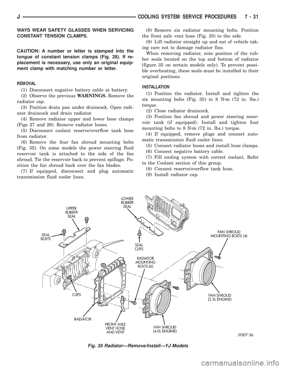
(6) Remove the four fan shroud mounting bolts
(Fig. 35). On some models the power steering fluid
reservoir tank is attached to the side of the fan
shroud. Tie the reservoir back to prevent spillage. Po-
sition the fan shroud back over the fan blades.
(7) If equipped, disconnect and plug automatic
transmission fluid cooler lines.(8) Remove six radiator mounting bolts. Position
the front axle vent hose (Fig. 35) to the side.
(9) Lift radiator straight up and out of vehicle tak-
ing care not to damage radiator fins.
When removing radiator, note position of the rub-
ber seals located on the top and bottom of radiator
(figure 35 on certain models only). To prevent possi-
ble overheating, these seals must be installed to their
original positions.
INSTALLATION
(1) Position the radiator. Install and tighten the
six mounting bolts (Fig. 35) to 8 Nzm (72 in. lbs.)
torque.
(2) Close radiator draincock.
(3) Position fan shroud and power steering reser-
voir tank (if equipped). Install and tighten four
mounting bolts to 8 Nzm (72 in. lbs.) torque.
(4) If equipped, remove plugs and connect auto-
matic transmission fluid cooler lines.
(5) Connect radiator hoses and install hose clamps.
(6) Connect negative battery cable.
(7) Fill cooling system with correct coolant. Refer
to the Coolant section of this group.
(8) Connect reserve/overflow tank hose.
(9) Install radiator cap.
Fig. 35 RadiatorÐRemove/InstallÐYJ Models
JCOOLING SYSTEM SERVICE PROCEDURES 7 - 31