1995 JEEP CHEROKEE steering
[x] Cancel search: steeringPage 265 of 2198
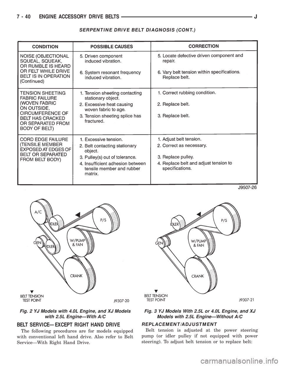
BELT SERVICEÐEXCEPT RIGHT HAND DRIVE
The following procedures are for models equipped
with conventional left hand drive. Also refer to Belt
ServiceÐWith Right Hand Drive.
REPLACEMENT/ADJUSTMENT
Belt tension is adjusted at the power steering
pump (or idler pulley if not equipped with power
steering). To adjust belt tension or to replace belt:
SERPENTINE DRIVE BELT DIAGNOSIS (CONT.)
Fig. 2 YJ Models with 4.0L Engine, and XJ Models
with 2.5L EngineÐWith A/CFig. 3 YJ Models With 2.5L or 4.0L Engine, and XJ
Models with 2.5L EngineÐWithout A/C
7 - 40 ENGINE ACCESSORY DRIVE BELTSJ
Page 266 of 2198
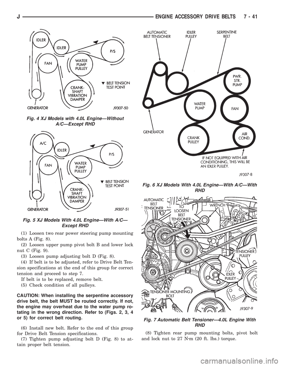
(1) Loosen two rear power steering pump mounting
bolts A (Fig. 8).
(2) Loosen upper pump pivot bolt B and lower lock
nut C (Fig. 9).
(3) Loosen pump adjusting bolt D (Fig. 8).
(4) If belt is to be adjusted, refer to Drive Belt Ten-
sion specifications at the end of this group for correct
tension and proceed to step 7.
If belt is to be replaced, remove belt.
(5) Check condition of all pulleys.
CAUTION: When installing the serpentine accessory
drive belt, the belt MUST be routed correctly. If not,
the engine may overheat due to the water pump ro-
tating in the wrong direction. Refer to (Figs. 2, 3, 4
or 5) for correct belt routing.
(6) Install new belt. Refer to the end of this group
for Drive Belt Tension specifications.
(7) Tighten pump adjusting bolt D (Fig. 8) to at-
tain proper belt tension.(8) Tighten rear pump mounting bolts, pivot bolt
and lock nut to 27 Nzm (20 ft. lbs.) torque.
Fig. 4 XJ Models with 4.0L EngineÐWithout
A/CÐExcept RHD
Fig. 5 XJ Models With 4.0L EngineÐWith A/CÐ
Except RHD
Fig. 6 XJ Models With 4.0L EngineÐWith A/CÐWith
RHD
Fig. 7 Automatic Belt TensionerÐ4.0L Engine With
RHD
JENGINE ACCESSORY DRIVE BELTS 7 - 41
Page 267 of 2198
(9) After power steering pump has been tightened
into position, recheck belt tension. Adjust if neces-
sary.
BELT SERVICEÐXJ MODELS WITH RIGHT HAND
DRIVE
The automatic belt tensioner is used only on
XJ models equipped with a 4.0L 6-cylinder en-
gine with right hand drive steering system.
REMOVAL
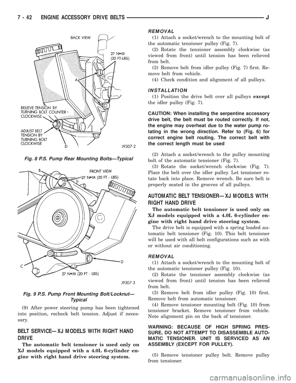
(1) Attach a socket/wrench to the mounting bolt of
the automatic tensioner pulley (Fig. 7).
(2) Rotate the tensioner assembly clockwise (as
viewed from front) until tension has been relieved
from belt.
(3) Remove belt from idler pulley (Fig. 7) first. Re-
move belt from vehicle.
(4) Check condition and alignment of all pulleys.
INSTALLATION
(1) Position the drive belt over all pulleysexcept
the idler pulley (Fig. 7).
CAUTION: When installing the serpentine accessory
drive belt, the belt must be routed correctly. If not,
the engine may overheat due to the water pump ro-
tating in the wrong direction. Refer to (Fig. 6) for
correct engine belt routing. The correct belt with
the correct length must be used
(2) Attach a socket/wrench to the pulley mounting
bolt of the automatic tensioner (Fig. 7).
(3) Rotate the socket/wrench clockwise (Fig. 7).
Place the belt over the idler pulley. Let tensioner ro-
tate back into place. Remove wrench. Be sure belt is
properly seated in the grooves of all pulleys.
AUTOMATIC BELT TENSIONERÐXJ MODELS WITH
RIGHT HAND DRIVE
The automatic belt tensioner is used only on
XJ models equipped with a 4.0L 6-cylinder en-
gine with right hand drive steering system.
The drive belt is equipped with a spring loaded au-
tomatic belt tensioner (Fig. 10). This belt tensioner
will be used with all belt configurations such as with
or without air conditioning.
REMOVAL
(1) Attach a socket/wrench to the mounting bolt of
the automatic tensioner pulley (Fig. 10).
(2) Rotate the tensioner assembly clockwise (as
viewed from front) until tension has been relieved
from belt.
(3) Remove belt from idler pulley (Fig. 10) first.
Remove belt from automatic tensioner.
(4) Remove tensioner mounting bolt (Fig. 10) from
tensioner bracket. Remove tensioner from vehicle.
Note alignment pin on the back of tensioner.
WARNING: BECAUSE OF HIGH SPRING PRES-
SURE, DO NOT ATTEMPT TO DISASSEMBLE AUTO-
MATIC TENSIONER. UNIT IS SERVICED AS AN
ASSEMBLY (EXCEPT FOR PULLEY).
(5) Remove tensioner pulley bolt. Remove pulley
from tensioner.
Fig. 8 P.S. Pump Rear Mounting BoltsÐTypical
Fig. 9 P.S. Pump Front Mounting Bolt/LocknutÐ
Typical
7 - 42 ENGINE ACCESSORY DRIVE BELTSJ
Page 337 of 2198
IGNITION SWITCHÐXJ MODELS
IGNITION SWITCH AND KEY CYLINDER SERVICE
The ignition switch is located on the steering col-
umn. The Key-In-Switch and Halo Light are integral
with the ignition switch. Refer to Group 8U for Key-
In-Switch and Halo Light diagnosis for XJ models.
Refer to Group 8W, Wiring for ignition switch wir-
ing circuits.
REMOVAL
(1) Disconnect negative battery cable from battery.
(2) If vehicle has a tilt column, remove tilt lever by
turning it counterclockwise.
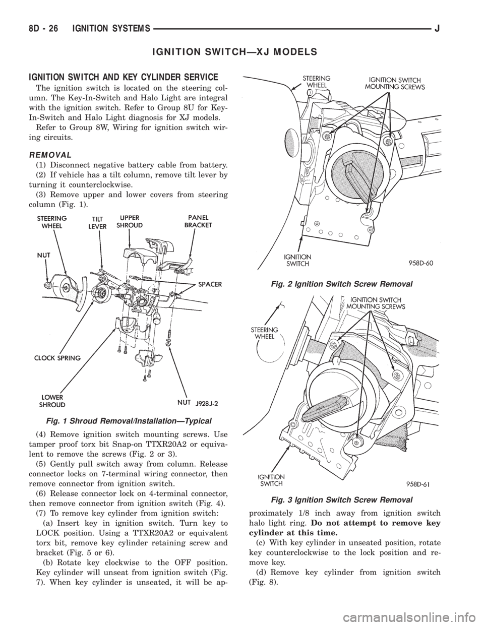
(3) Remove upper and lower covers from steering
column (Fig. 1).
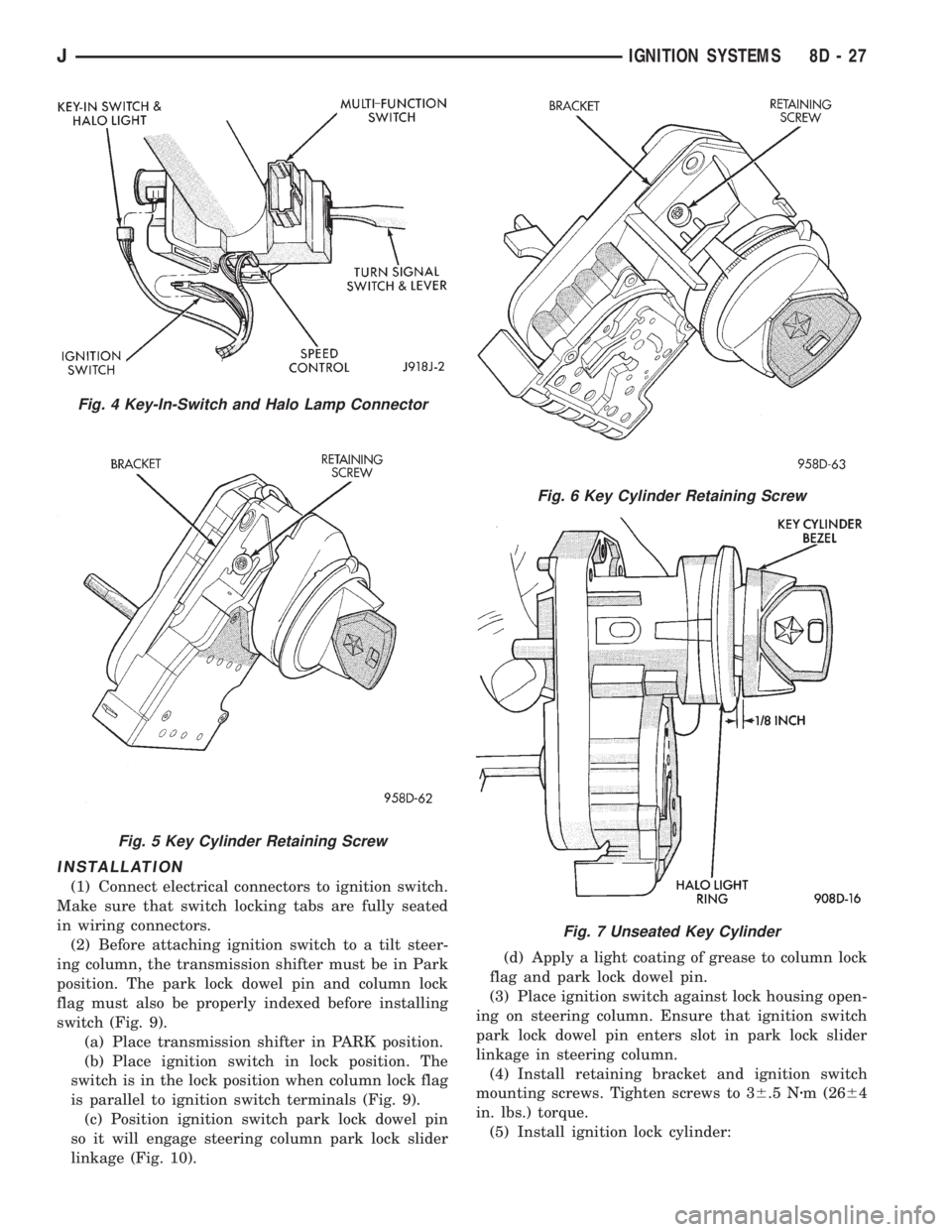
(4) Remove ignition switch mounting screws. Use
tamper proof torx bit Snap-on TTXR20A2 or equiva-
lent to remove the screws (Fig. 2 or 3).
(5) Gently pull switch away from column. Release
connector locks on 7-terminal wiring connector, then
remove connector from ignition switch.
(6) Release connector lock on 4-terminal connector,
then remove connector from ignition switch (Fig. 4).
(7) To remove key cylinder from ignition switch:
(a) Insert key in ignition switch. Turn key to
LOCK position. Using a TTXR20A2 or equivalent
torx bit, remove key cylinder retaining screw and
bracket (Fig. 5 or 6).
(b) Rotate key clockwise to the OFF position.
Key cylinder will unseat from ignition switch (Fig.
7). When key cylinder is unseated, it will be ap-proximately 1/8 inch away from ignition switch
halo light ring.Do not attempt to remove key
cylinder at this time.
(c) With key cylinder in unseated position, rotate
key counterclockwise to the lock position and re-
move key.
(d) Remove key cylinder from ignition switch
(Fig. 8).
Fig. 1 Shroud Removal/InstallationÐTypical
Fig. 2 Ignition Switch Screw Removal
Fig. 3 Ignition Switch Screw Removal
8D - 26 IGNITION SYSTEMSJ
Page 338 of 2198
INSTALLATION
(1) Connect electrical connectors to ignition switch.
Make sure that switch locking tabs are fully seated
in wiring connectors.
(2) Before attaching ignition switch to a tilt steer-
ing column, the transmission shifter must be in Park
position. The park lock dowel pin and column lock
flag must also be properly indexed before installing
switch (Fig. 9).
(a) Place transmission shifter in PARK position.
(b) Place ignition switch in lock position. The
switch is in the lock position when column lock flag
is parallel to ignition switch terminals (Fig. 9).
(c) Position ignition switch park lock dowel pin
so it will engage steering column park lock slider
linkage (Fig. 10).(d) Apply a light coating of grease to column lock
flag and park lock dowel pin.
(3) Place ignition switch against lock housing open-
ing on steering column. Ensure that ignition switch
park lock dowel pin enters slot in park lock slider
linkage in steering column.
(4) Install retaining bracket and ignition switch
mounting screws. Tighten screws to 36.5 Nzm (2664
in. lbs.) torque.
(5) Install ignition lock cylinder:
Fig. 4 Key-In-Switch and Halo Lamp Connector
Fig. 5 Key Cylinder Retaining Screw
Fig. 6 Key Cylinder Retaining Screw
Fig. 7 Unseated Key Cylinder
JIGNITION SYSTEMS 8D - 27
Page 339 of 2198
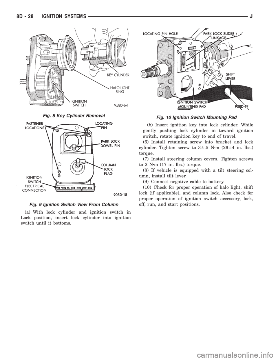
(a) With lock cylinder and ignition switch in
Lock position, insert lock cylinder into ignition
switch until it bottoms.(b) Insert ignition key into lock cylinder. While
gently pushing lock cylinder in toward ignition
switch, rotate ignition key to end of travel.
(6) Install retaining screw into bracket and lock
cylinder. Tighten screw to 36.5 Nzm (2664 in. lbs.)
torque.
(7) Install steering column covers. Tighten screws
to2Nzm (17 in. lbs.) torque.
(8) If vehicle is equipped with a tilt steering col-
umn, install tilt lever.
(9) Connect negative cable to battery.
(10) Check for proper operation of halo light, shift
lock (if applicable), and column lock. Also check for
proper operation of ignition switch accessory, lock,
off, run, and start positions.
Fig. 10 Ignition Switch Mounting PadFig. 8 Key Cylinder Removal
Fig. 9 Ignition Switch View From Column
8D - 28 IGNITION SYSTEMSJ
Page 340 of 2198

IGNITION SWITCHÐYJ MODELS
GENERAL INFORMATION
This section will cover the electrical portion
of the ignition switch. To service the mechani-
cal ignition key switch, refer to Group 19,
Steering.
Refer to Group 8W, Wiring for ignition switch wir-
ing circuits.
The ignition switch is mounted under the instru-
ment panel on the lower section of the steering col-
umn. The headlamp dimmer switch is mounted
beside the ignition switch (Fig. 11). Both of these
switches (ignition and dimmer) share the same
mounting screws.
The switch is connected to the ignition key lock as-
sembly by a remote actuator rod. This remote actua-
tor rod fits into an access hole on the bottom of the
ignition switch (Fig. 12).
REMOVAL
(1) Disconnect the negative battery cable at the
battery.
(2) Remove the windshield wiper intermittent con-
trol module and its bracket (if equipped).
(3) Place the ignition key lock in ACCESSORY po-
sition.
(4) Remove the two headlamp dimmer switch at-
taching nuts. Lift the switch from steering column
while disengaging actuator rod.
Before removing dimmer switch, tape the two
remote control actuator rods (ignition switchand dimmer) to the steering column. This will
prevent accidental disengagement from the up-
per part of the steering column.
(5) Remove the ignition switch-to-steering column
attaching screws.
(6) Disengage the ignition switch from the remote
actuator rod by lifting straight up. Remove switch
from steering column.
(7) Remove wiring from switch as follows:
Two electrical connectors are used to connect all
wiring to the ignition switch. One of the connectors is
installed (interlocked) over the top of the other con-
nector. Remove wiring from switch by disconnecting
the (black) harness connector first and then the other
connector. Remove the switch from the vehicle.
SWITCH TESTING
To test the ignition switch circuity and continuity,
proceed as follows. Place the slide bar (on the igni-
tion switch) (Fig. 12) into the detent position to be
tested. An ohmmeter or continuity light may be used
to check switch continuity. Refer to the Ignition
Switch Continuity Tests chart for continuity tests.
Refer to (Fig. 13) for the lettered/numbered terminal
positions.All wiring must be disconnected from
the ignition switch before performing any con-
tinuity testing.
There are five positions on the ignition switch. The
switch positions (in order) are: ACCESSORY, OFF-
LOCK, OFF, ON AND START (Figs. 14 or 15). Each
position has a detent stop (except START), which isFig. 11 Ignition Switch/Headlamp Dimmer SwitchÐ
Typical
Fig. 12 Ignition Switch/Remote Actuator RodÐ
Typical
JIGNITION SYSTEMS 8D - 29
Page 341 of 2198

spring loaded to release when the key is released.
The maximum voltage drop between any two con-
nected terminals should not exceed 12.5 millivolts
per amp. For example: If a 10 amp load is drawn
through the switch, maximum voltage drop should be
10 x 0.0125 or 0.125 volt.
INSTALLATION/ADJUSTMENT
(1) Place the key lock switch in the ACCESSORY
position.
(2) Place the slider bar (in the ignition switch)
(Fig. 12) into the ACCESSORY detent position.
(3) Connect the wiring to the switch as follows: In-
stall the non-black (colored) connector first and then
the black (colored) connector to the ignition switch.
One connector will interlock the other connector.
(4) Slip the remote actuator rod into the access
hole on the switch (Fig. 12). Install the switch to the
steering column. Be careful not to move the slider
bar (on the switch) out of the ACCESSORY detent
position. Remove the ignition switch actuator rod se-
curing-tape from steering column.
(5) Install the two ignition switch-to-steering col-
umn screws finger tight.Do not tighten screws at
this time.
(6) Adjust ignition switch as follows:
(a) Non-tilt steering column: While holding key
lock switch in ACCESSORY position, gently slide
ignition switchup(towards steering wheel). This
will remove slack from switch. Tighten attaching
screws. Do not allow the ignition switch to move
from the ACCESSORY detent position.
(b) Tilt steering column: While holding the key
lock switch in the ACCESSORY position, gently
slide the ignition switchdown(away from steering
wheel) to remove slack from switch. Tighten at-
taching screws. Do not allow the ignition switch to
move from the ACCESSORY detent position.
Because the ignition switch and the headlamp dim-
mer switch share the same two mounting screws, oneof the screws must be removed from the ignition
switch. This must be doneafterthe ignition switch
has been adjusted andbeforethe dimmer switch
has been installed. Remove one screw.Do notre-
move the stud/nut.
(7) Install the headlamp dimmer switch as follows:
Slip switch into actuator rod and position over the ig-
IGNITION SWITCH CONTINUITY TESTS
Fig. 13 Ignition Switch Terminals/Circuits
8D - 30 IGNITION SYSTEMSJ