Page 901 of 1771
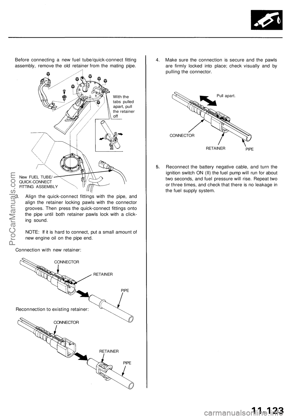
Before connecting a new fuel tube/quick-connect fitting
assembly, remove the old retainer from the mating pipe.
With the
tabs pulled
apart, pull
the retainer
off
New FUEL TUBE/
QUICK-CONNECT
FITTING ASSEMBLY
3. Align the quick-connect fittings with the pipe, and
align the retainer locking pawls with the connector
grooves. Then press the quick-connect fittings onto
the pipe until both retainer pawls lock with a click-
ing sound.
NOTE: If it is hard to connect, put a small amount of
new engine oil on the pipe end.
Connection with new retainer:
CONNECTOR
RETAINER
PIPE
CONNECTOR
RETAINER
PIPE
4. Make sure the connection is secure and the pawls
are firmly locked into place; check visually and by
pulling the connector.
Pull apart.
CONNECTOR
RETAINER
PIPE
Reconnect the battery negative cable, and turn the
ignition switch ON (II) the fuel pump will run for about
two seconds, and fuel pressure will rise. Repeat two
or three times, and check that there is no leakage in
the fuel supply system.
Reconnection to existing retainer:ProCarManuals.com
Page 977 of 1771
Troubleshooting Procedure s
(cont'd)
SRS component s ar e locate d in thi s area . Revie w th e SR S
componen t locations , precautions , an d procedure s in th e
SR S (sectio n 24 ) befor e performin g repair s o r service .
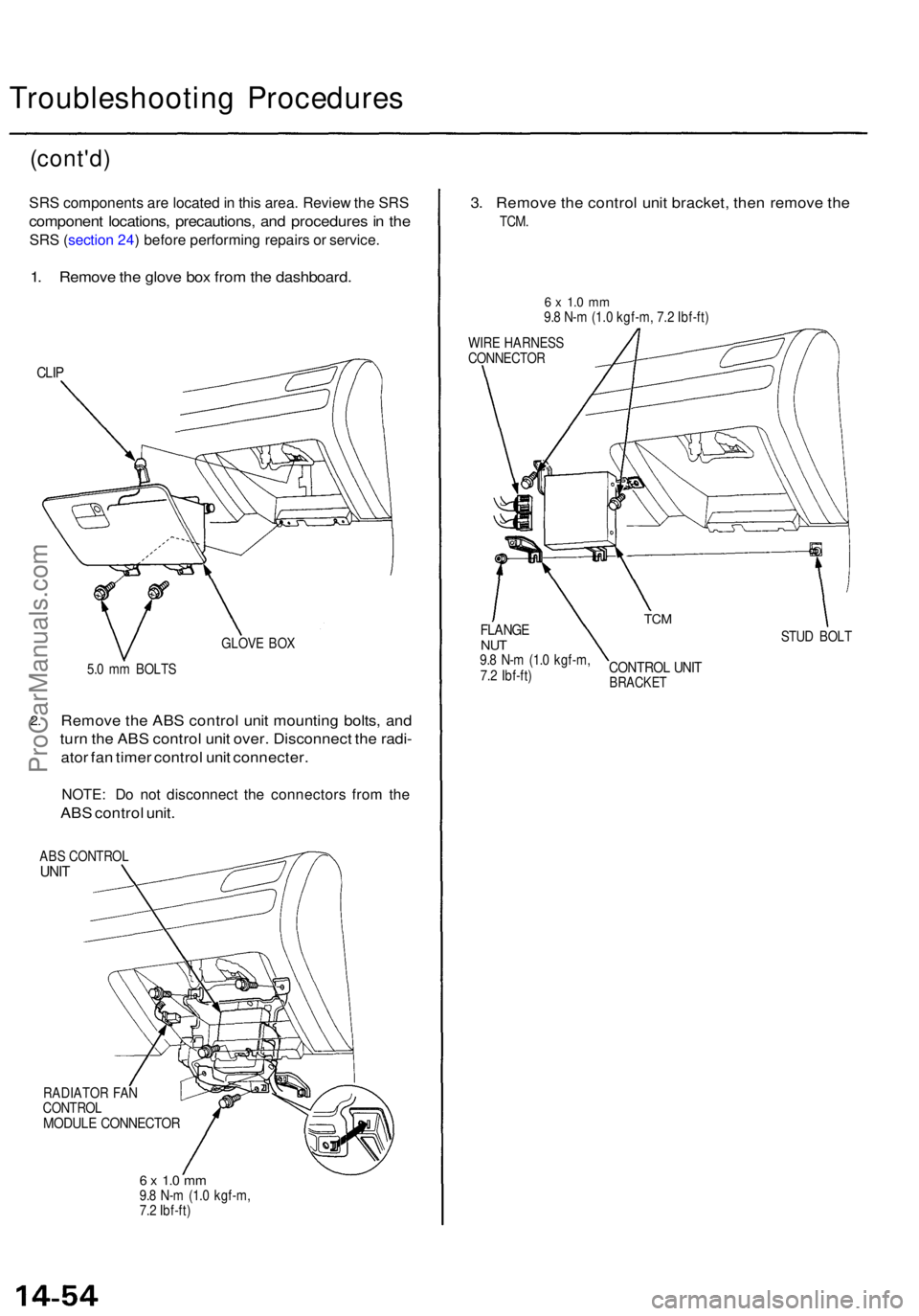
1. Remov e th e glov e bo x fro m th e dashboard .
CLIP
GLOV E BO X
5. 0 m m BOLT S
2.Remov e th e AB S contro l uni t mountin g bolts , an d
tur n th e AB S contro l uni t over . Disconnec t th e radi -
ato r fa n time r contro l uni t connecter .
NOTE: D o no t disconnec t th e connector s fro m th e
AB S contro l unit .
ABS CONTRO LUNIT
RADIATO R FA N
CONTRO L
MODULE CONNECTO R
6 x 1. 0 m m9.8 N- m (1. 0 kgf-m ,
7. 2 Ibf-ft )
3. Remov e th e contro l uni t bracket , the n remov e th e
TCM .
6 x 1. 0 m m9.8 N- m (1. 0 kgf-m , 7. 2 Ibf-ft )
WIR E HARNES S
CONNECTO R
STUD BOL T
CONTRO L UNI TBRACKE T
TCMFLANG ENUT9.8 N- m (1. 0 kgf-m ,
7. 2 Ibf-ft )
ProCarManuals.com
Page 986 of 1771
Transmission Contro l Modul e (TCM )
Replacemen t
SRS component s ar e locate d in thi s area . Revie w th e SR S
componen t locations , precautions , an d procedure s i n th e
SR S (sectio n 24 ) befor e performin g repair s o r service .
1 . Remov e th e glov e bo x fro m th e dashboard .
CLIP
GLOV E BO X
2.
5. 0 m m BOLT S
Remov e th e AB S contro l uni t mountin g bolts , an d
tur n th e AB S contro l uni t over . Disconnec t th e radi -
ato r fa n time r contro l uni t connector .
NOTE : D o no t disconnec t th e connector s fro m th e
AB S contro l unit .
ABS CONTRO LUNIT
RADIATO R FA N
TIME R CONTRO L
UNIT CONNECTO R
6 x 1. 0 m m9.8 N- m(1.0 kgf-m , 7. 2 Ibf-ft )
3. Remov e th e contro l uni t bracket , the n remov e th e
TCM . Disconnec t th e connector s an d replac e th e
TCM .
6 x 1. 0 m m9.8 N- m (1. 0 kgf-m , 7. 2 Ibf-ft )
WIR E HARNES S
CONNECTO R
STUD BOL TFLANG E NU T
9. 8 N- m (1. 0 kgf-m ,
7. 2 Ibf-ft )
CONTRO L UNI TBRACKE T
TCM
ProCarManuals.com
Page 1176 of 1771

Inspection
Check th e steerin g colum n bal l bearin g an d th e steer -
in g join t bearing s fo r pla y an d prope r movement . I f
ther e is nois e o r i f ther e is excessiv e play , replac e th e
steerin g colum n a s a n assembly .
Chec k th e retainin g colla r fo r damage . I f i t i s dam -
aged , replac e th e retainin g collar .
Chec k th e absorbin g plates , absorbin g plat e guide s
an d slidin g capsule s fo r distortio n an d breakage .
Replac e th e steerin g colum n a s a n assembl y i f the y
ar e distorte d o r broken .
ABSORBIN G PLAT E
RETAININ G COLLA R
STEERIN G JOIN TBEARING S
SLIDING CAPSUL E
Thi s par t i s attache d
t o th e colum n bracke t
with th e plasti c injections .
COLUMN BAL L BEARIN G
IGNITIO N SWITC H
se e sectio n 23 .
1. Mov e th e til t leve r fro m th e loos e positio n t o loc k
positio n 3 to 5 times ; the n measur e th e til t leve r
preloa d 1 0 m m (0. 4 in ) fro m th e en d o f th e til t lever .
Preload : 7 0 - 9 0 N (7 - 9 kgf , 15-2 0 Ibf )
2. I f th e measuremen t i s ou t o f th e specification ,
adjus t th e preloa d usin g th e followin g procedures .
a . Loose n th e til t lever , an d se t th e steerin g colum n
i n th e neutra l position .
b . Remov e th e 6 m m loc k bol t an d remov e th e stop .
c . Adjus t th e preloa d b y turnin g th e til t loc k bol t lef t
o r right .
d. Pul l u p th e til t leve r t o th e uppermos t positio n
and instal l th e stop . Chec k th e preloa d again . I f
th e measuremen t i s stil l ou t o f specification ,
repeat th e abov e procedure s (a ) throug h (c ) t o
adjust .
CAUTION : B e carefu l no t t o loose n th e til t leve r
whe n installin g th e sto p o r tightenin g th e 6 m m
loc k bolt .
SPRIN G SCAL E
(Commerciall y available )
TIL T LOC K BOL T
Tighte n th e loc k bol t wit hthe til t leve r raised .
STOP 6
m m LOC K BOL T
9. 8 N- m (1. 0 kgf-m , 7 Ibf-ft )
PLASTI
C
INJECTION S
ABSORBIN G PLAT EGUIDE
ProCarManuals.com
Page 1210 of 1771
Steering Gearbo x
Reassembl y (cont'd )
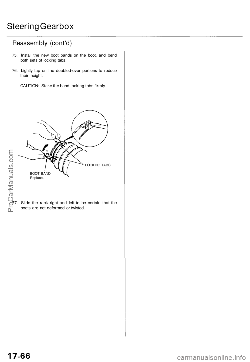
75. Instal l th e ne w boo t band s o n th e boot , an d ben d
bot h set s o f lockin g tabs .
76 . Lightl y ta p o n th e doubled-ove r portion s t o reduc e
thei r height .
CAUTION : Stak e th e ban d lockin g tab s firmly .
LOCKIN G TAB S
BOO T BAN D
Replace .
77. Slid e th e rac k righ t an d lef t t o b e certai n tha t th e
boot s ar e no t deforme d o r twisted .
ProCarManuals.com
Page 1280 of 1771
Brake Hoses/Lines
Inspection ('95, '96 models)
1. Inspect the brake hoses for damage, deterioration, leaks, interference and twisting.
2. Check the brake lines for damage, rusting and leakage. Also check for bent brake lines.
3. Check for leaks at hose and line joints and connections, and retighten if necessary.
4. Check the master cylinder and ABS modulator unit for damage and leakage.
CAUTION: Replace the brake hose clip whenever the brake hose is serviced.
MASTER CYLINDER-to-BRAKE LINE
19 N-m (1.9 kgf-m, 14 Ibf-ft)
BRAKE LINE-to-MODULATOR UNIT
19 N-m (1.9 kgf-m, 14 Ibf-ft)
BLEED SCREW
9 N-m (0.9 kgf-m, 6.5 Ibf-ft)
BRAKE HOSE-to-CALIPER
(BANJO BOLT)
34 N-m (3.5 kgf-m, 25 Ibf-ft)
BRAKE HOSE-to-CALIPER
(BANJO BOLT)
34 N-m (3.5 kgf-m, 25 Ibf-ft)
BLEED SCREW
9 N-m (0.9 kgf-m, 6.5 Ibf-ft)
BRAKE LINE-to-BRAKE HOSE
15 N-m (1.5 kgf-m, 11 Ibf-ft)
BRAKE LINE-to-4-WAY JOINT
19 N-m (1.9 kgf-m, 14 Ibf-ft)
BRAKE LINE-to-BRAKE HOSE
15 N-m (1.5 kgf-m, 11 Ibf-ft)ProCarManuals.com
Page 1281 of 1771
Brake Hoses/Lines
Inspection ('97 - '98 models)
1. Inspect the brake hoses for damage, deterioration, leaks, interference and twisting.
2. Check the brake lines for damage, rusting and leakage. Also check for bent brake lines.
3. Check for leaks at hose and line joints and connections, and retighten if necessary.
4. Check the master cylinder and ABS modulator unit for damage and leakage.
CAUTION: Replace the brake hose clip whenever the brake hose is serviced.
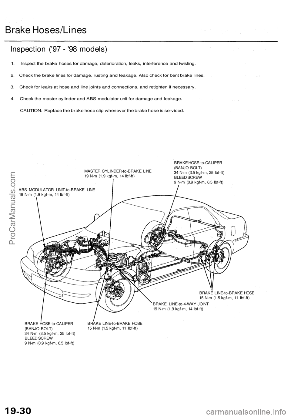
MASTER CYLINDER-to-BRAKE LINE
19 N-m (1.9 kgf-m, 14 Ibf-ft)
ABS MODULATOR UNIT-to-BRAKE LINE
19 N-m (1.9 kgf-m, 14 Ibf-ft)
BRAKE HOSE-to-CALIPER
(BANJO BOLT)
34 N-m (3.5 kgf-m, 25 Ibf-ft)
BLEED SCREW
9 N-m (0.9 kgf-m, 6.5 Ibf-ft)
BRAKE LINE-to-BRAKE HOSE
15 N-m (1.5 kgf-m, 11 Ibf-ft)
BRAKE LINE-to-4-WAY JOINT
19 N-m (1.9 kgf-m, 14 Ibf-ft)
BRAKE HOSE-to-CALIPER
(BANJO BOLT)
34 N-m (3.5 kgf-m, 25 Ibf-ft)
BLEED SCREW
9 N-m (0.9 kgf-m, 6.5 Ibf-ft)
BRAKE LINE-to-BRAKE HOSE
15 N-m (1.5 kgf-m, 11 Ibf-ft)ProCarManuals.com
Page 1285 of 1771
Illustrated Inde x
The accumulato r contain s high-pressur e nitroge n gas ; d o no t puncture , expos e to flame , o r attemp t t o dis -
assembl e th e accumulato r o r i t ma y explode ; sever e persona l injur y ma y result .
MODULATO R UNI T
AB S Functio n Test , pag e 19-11 2
Modulato r Functio n Check , pag e 19-11 4
Relievin g Syste m Pressure , pag e 19-11 5
Brak e Flui d Replacement , pag e 19-11 5
Removal/Installation , pag e 19-11 7
Wir e Harnes s Replacement , pag e 19-11 9
Pum p Moto r Replacement , pag e 19-11 9
Accumulato r Replacemen t an d Disposal , pag e 19-12 0
Reservoi r Replacement , pag e 19-12 0FAIL-SAF E RELAY SInspection , pag e 19-12 2
AB S CONTRO L UNI T
Replacement , pag e 19-12 1
REAR WHEE L SENSO RInspection , pag e 19-12 2
Replacement , pag e 19-12 3
ABS MOTO R RELA YInspection , pag e 19-12 2
FRON T WHEE L SENSO RInspection , pag e 19-12 2Replacement , pag e 19-12 3
ProCarManuals.com