Page 828 of 1771

Thermostat Radiato
r Fa n Switche s
Testing
Replac e th e thermosta t i f i t i s ope n a t roo m temperature .
T o tes t a close d thermostat :
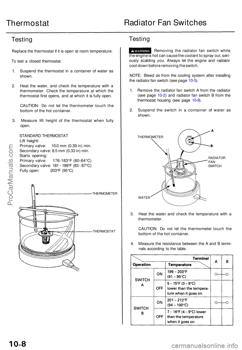
1 . Suspen d th e thermosta t i n a containe r o f wate r a s
shown .
2 . Hea t th e water , an d chec k th e temperatur e wit h a
thermometer . Chec k th e temperatur e a t whic h th e
thermosta t firs t opens , an d a t whic h i t i s full y open .
CAUTION : D o no t le t th e thermomete r touc h th e
botto m of th e ho t container .
3 . Measur e lif t heigh t of the thermosta t whe n full y
open .
STANDAR D THERMOSTA T
Lift height :
Primar y valve : 10. 0 m m (0.3 9 in ) min .
Secondar y valve : 8. 5 m m (0.3 3 in ) min .
Start s opening :
Primar y valve : 176-183° F (80-84°C )
Secondar y valve : 18 1 - 189° F (8 3 - 87°C )
Full y open : 203° F (95°C )
THERMOMETE R
THERMOSTA T
Testing
Removin g th e radiato r fa n switc h whil e
th e engin e is ho t ca n caus e th e coolan t t o spra y out , seri -
ousl y scaldin g you . Alway s le t th e engin e an d radiato r
coo l dow n befor e removin g th e switch .
NOTE : Blee d ai r fro m th e coolin g syste m afte r installin g
th e radiato r fa n switc h (se e pag e 10-5 ).
1 . Remov e th e radiato r fa n switc h A fro m th e radiato r
(se e pag e 10-2 ) an d radiato r fa n switc h B fro m th e
thermosta t housin g (se e pag e 10-9 ).
2 . Suspen d th e switc h i n a containe r of wate r a s
shown .
THERMOMETE R
RADIATORFANSWITC H
WATER
3. Hea t th e wate r an d chec k th e temperatur e wit h a
thermometer .
CAUTION : D o no t le t th e thermomete r touc h th e
botto m of th e ho t container .
4 . Measur e th e resistanc e betwee n th e A an d B termi -
nal s accordin g t o th e table .
ProCarManuals.com
Page 1210 of 1771
Steering Gearbo x
Reassembl y (cont'd )
75. Instal l th e ne w boo t band s o n th e boot , an d ben d
bot h set s o f lockin g tabs .
76 . Lightl y ta p o n th e doubled-ove r portion s t o reduc e
thei r height .
CAUTION : Stak e th e ban d lockin g tab s firmly .
LOCKIN G TAB S
BOO T BAN D
Replace .
77. Slid e th e rac k righ t an d lef t t o b e certai n tha t th e
boot s ar e no t deforme d o r twisted .
ProCarManuals.com
Page 1263 of 1771

Brake Booster
Inspection
Functional Test
1. With the engine stopped, depress the brake pedal
several times to deplete the vacuum reservoir, then
depress the pedal hard and hold it for 15 seconds. If
the pedal sinks, either the master cylinder is
bypassing internally, or the brake system (master
cylinder, lines, modulator, proportioning valve, or
caliper) is leaking.
2. Start the engine with the pedal depressed. If the
pedal sinks slightly, the vacuum booster is operat-
ing normally. If the pedal height does not vary, the
booster or check valve is faulty.
3. With the engine running, depress the brake pedal
lightly. Apply just enough pressure to hold back
automatic transmission creep. If the brake pedal
sinks more than 25 mm (1.0 in.) in three minutes, the
master cylinder is faulty. A slight change in pedal
height when the A/C compressor cycles on and off if
normal. (The A/C compressor load changes the vac-
uum available to the booster.)
Leak Test
1. Depress the brake pedal with the engine running,
then stop the engine. If the pedal height does not
vary while depressed for 30 seconds, the vacuum
booster is OK. If the pedal rises, the booster is faulty.
2. With the engine stopped, depress the brake pedal
several times using normal pressure. When the
pedal is first depressed, it should be low. On consec-
utive applications, the pedal height should gradually
rise. If the pedal position does not vary, check the
booster check valve.ProCarManuals.com
Page 1432 of 1771

Front Sea t
Reclin e Adjuster , Slide/Up-dow n Adjuste r Replacemen t
CAUTION: Wea r glove s t o remov e an d instal l th e reclin e
adjuste r an d slide/up-dow n adjuster .
NOTE :
Tak e car e no t t o scratc h th e sea t cover s an d body .
Befor e removin g th e fron t seat , rais e th e sea t cushio n
to it s fron t maximu m height .
1. Remov e th e fron t sea t throug h th e doo r openin g (se e
pag e 20-71 ).
2 . Remov e th e seat-bac k an d sea t cushio n (se e page s
20-72 , 20-74 ).
3 . I f necessary , remov e th e sea t bel t buckl e (se e pag e
20-89 ) an d reclin e adjuste r cove r (se e pag e 20-73 ).
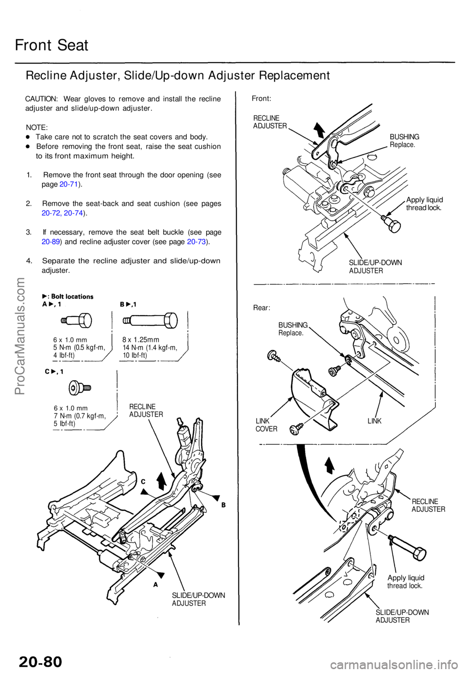
4 . Separat e th e reclin e adjuste r an d slide/up-dow n
adjuster.
6 x 1. 0 m m5 N- m (0. 5 kgf-m ,4 Ibf-ft )
6 x 1. 0 m m7 N- m (0. 7 kgf-m ,5 Ibf-ft )
8 x 1.25m m14 N- m (1. 4 kgf-m ,10 Ibf-ft )
RECLIN EADJUSTE R
SLIDE/UP-DOW NADJUSTER
Front:
RECLIN EADJUSTE R
BUSHINGReplace .
Apply liqui d
threa d lock .
Rear :
BUSHIN GReplace .
LINKCOVE R
SLIDE/UP-DOW NADJUSTER
RECLINEADJUSTE R
Apply liqui dthrea d lock .
SLIDE/UP-DOW NADJUSTER
LINK
ProCarManuals.com
Page 1436 of 1771

Slide Motor , Slid e Gearbo x Replacemen t
CAUTION: Wea r glove s t o remov e an d instal l th e slid e
moto r an d slid e gearbox .
NOTE :
Tak e car e no t t o scratc h th e sea t cover .
T o remov e th e slid e moto r an d slid e gearbox , slid e th e
fron t sea t backwar d fully , an d rais e th e sea t cushio n t o
its fron t maximu m height .
1. Remov e th e fron t sea t throug h th e doo r openin g (se e
pag e 20-71 ).
2 . Remov e th e reclin e cove r (se e pag e 20-72 ).
3 . Remov e th e slid e join t cabl e (se e pag e 20-81 ).
4 . Disconnec t th e slid e moto r connector .
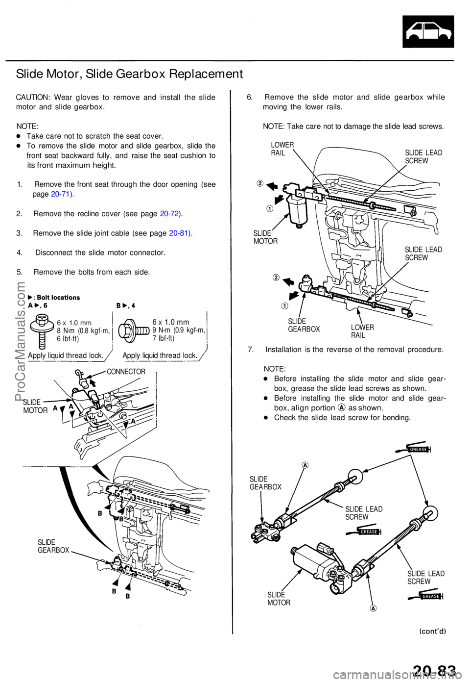
5 . Remov e th e bolt s fro m eac h side .
6 x 1. 0 m m8 N- m (0. 8 kgf-m ,
6 Ibf-ft )6 x 1. 0 m m9 N- m (0. 9 kgf-m ,
7 Ibf-ft )
SLID E
GEARBO X
6. Remov e th e slid e moto r an d slid e gearbo x whil e
movin g th e lowe r rails .
NOTE : Tak e car e no t t o damag e th e slid e lea d screws .
LOWERRAILSLID E LEA D
SCRE W
SLID E
MOTO R
SLIDE
GEARBO X LOWE
R
RAIL
7. Installatio n i s th e revers e o f th e remova l procedure .
NOTE:
Before installin g th e slid e moto r an d slid e gear -
box , greas e th e slid e lea d screw s a s shown .
Befor e installin g th e slid e moto r an d slid e gear -
box, alig n portio n a s shown .
Check th e slid e lea d scre w fo r bending .
SLIDEGEARBO X
SLIDE
MOTO R SLID
E LEA D
SCRE W
SLID E
MOTO R
CONNECTO R
SLIDE LEA D
SCRE W
SLIDE LEA D
SCRE W
Apply liqui d threa d lock .Apply liqui d threa d lock .
ProCarManuals.com
Page 1438 of 1771
Front Sea t
Front an d Rea r Up-dow n Motor s
Replacemen t
CAUTION: Wea r glove s t o remov e an d instal l th e fron t
an d rea r up-dow n motors .
NOTE:
• Tak e car e no t t o scratc h th e sea t covers .
• Befor e removin g th e fron t seat , rais e th e sea t cushio n
to it s maximu m height .
1. Remov e th e fron t sea t throug h th e doo r openin g
(see pag e 20-71 ).
2 . Remov e th e sea t cushio n (se e pag e 20-74 ).
3 . Fro m unde r th e sea t linkage , disconnec t th e fron t an d
rea r up-dow n moto r connectors , an d remov e th e
bolts .
REA R UP-DOW NMOTORFRONT UP-DOW NMOTOR
CONNECTO R
Bolt locations , 2
6 x 1. 0 m m5 N- m (0. 5 kgf-m ,4 Ibf-ft )
Apply liqui d threa d lock .
ProCarManuals.com
Page 1452 of 1771
Adjustment
NOTE: Before adjusting the hood, loosen each bolt slightly.
1. Adjust the hood hinges right and left, as well as fore and aft, by using the elongated holes.
2. Turn the hood edge cushions, as necessary, to make the hood fit flush with the body at front and side edges.
3. Adjust the hood latch to obtain the proper height at the forward edge.
4. After adjustment, tighten each bolt securely.
HOOD
HINGE
6 x 1.0 mm
9.8 N-m (1.0 kgf-m,
7.2 Ibf-ft)
HOOD EDGE
CUSHION
HOOD
LATCH
NOTE: Move the hood latch right or left until the striker
is centered in the hood latch as shown.
HOOD EDGE
CUSHIONS
(Body side)
HOOD
LATCH
STRIKER
HOOD
LATCH
6 x 1.0 mm
9.8 N-m (1.0 kgf-m,
7.2 Ibf-ft)
HOOD
HINGE
HOOD
HOODProCarManuals.com
Page:
< prev 1-8 9-16 17-24