Page 485 of 1771

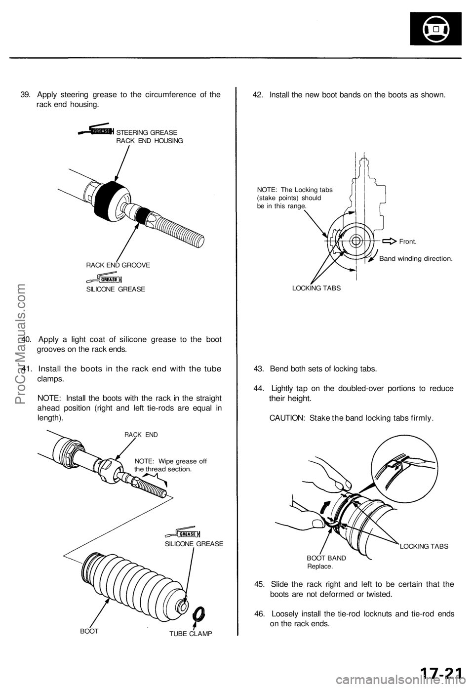
39. Appl y steerin g greas e t o th e circumferenc e o f th e
rac k en d housing .
STEERIN G GREAS E
RAC K EN D HOUSIN G
RAC K EN D GROOV E
40. Appl y a ligh t coa t o f silicon e greas e t o th e boo t
groove s o n th e rac k ends .
41. Instal l th e boot s i n th e rac k en d wit h th e tub e
clamps .
NOTE : Instal l th e boot s wit h th e rac k i n th e straigh t
ahea d positio n (righ t an d lef t tie-rod s ar e equa l i n
length) .
NOTE: Wip e greas e of fthe threa d section .
SILICON E GREAS E
BOO T
TUBE CLAM P
42. Instal l th e ne w boo t band s o n th e boot s a s shown .
NOTE: Th e Lockin g tab s
(stak e points ) shoul d
b e i n thi s range .
LOCKIN G TAB S
43. Ben d bot h set s o f lockin g tabs .
44 . Lightl y ta p o n th e doubled-ove r portion s t o reduc e
their height .
CAUTION : Stak e th e ban d lockin g tab s firmly .
LOCKIN G TAB S
BOO T BAN D
Replace .
45. Slid e th e rac k righ t an d lef t t o b e certai n tha t th e
boot s ar e no t deforme d o r twisted .
46 . Loosel y instal l th e tie-ro d locknut s an d tie-ro d end s
o n th e rac k ends .
SILICON E GREAS E
Band windin g direction .
Front.
RACK EN D
ProCarManuals.com
Page 551 of 1771
Adjustment
NOTE: Before adjusting the hood, remove the support strut on each side from the hood, and loosen each hood mounting
bolt slightly.
1. Adjust the hood right and left, as well as fore and aft, by using the elongated holes on the hood hinge.
2. Turn the hood edge cushions, as necessary, to make the hood fit flush with the body at front and side edges.
3. Adjust the hood latch to obtain the proper height at the forward edge.
4. After adjustment, tighten each bolt securely.
HOOD
HINGE
6 x 1.0 mm
9.8 N-m (1.0 kgf-m,
7.2 Ibf-ft)
HOOD
HOOD EDGE
CUSHION
HOOD
LATCH
NOTE: Move the hood latch right or left until the striker
is centered in the hood latch as shown.
HOOD
LATCH
STRIKER
HOOD EDGE
CUSHION
(Hood side)
HOOD EDGE
CUSHION
(Body side)
6 x 1.0 mm
9.8 N-m (1.0 kgf-m,
7.2 Ibf-ft)
HOOD
LATCH
HOOD
HOOD
HINGEProCarManuals.com
Page 686 of 1771
Lift and Support Points
Lift and Safety Stands
1. Place the lift blocks as shown.
2. Raise the hoist a few inches (centimeters), and rock the vehicle to be sure it is firmly supported.
3. Raise the hoist to full height, and inspect lift points for solid support.
NOTE: Use the same support points to support the vehicle on safety stands.
FRONT SUPPORT POINT
LIFT BLOCKS
REAR SUPPORT POINTProCarManuals.com
Page 723 of 1771

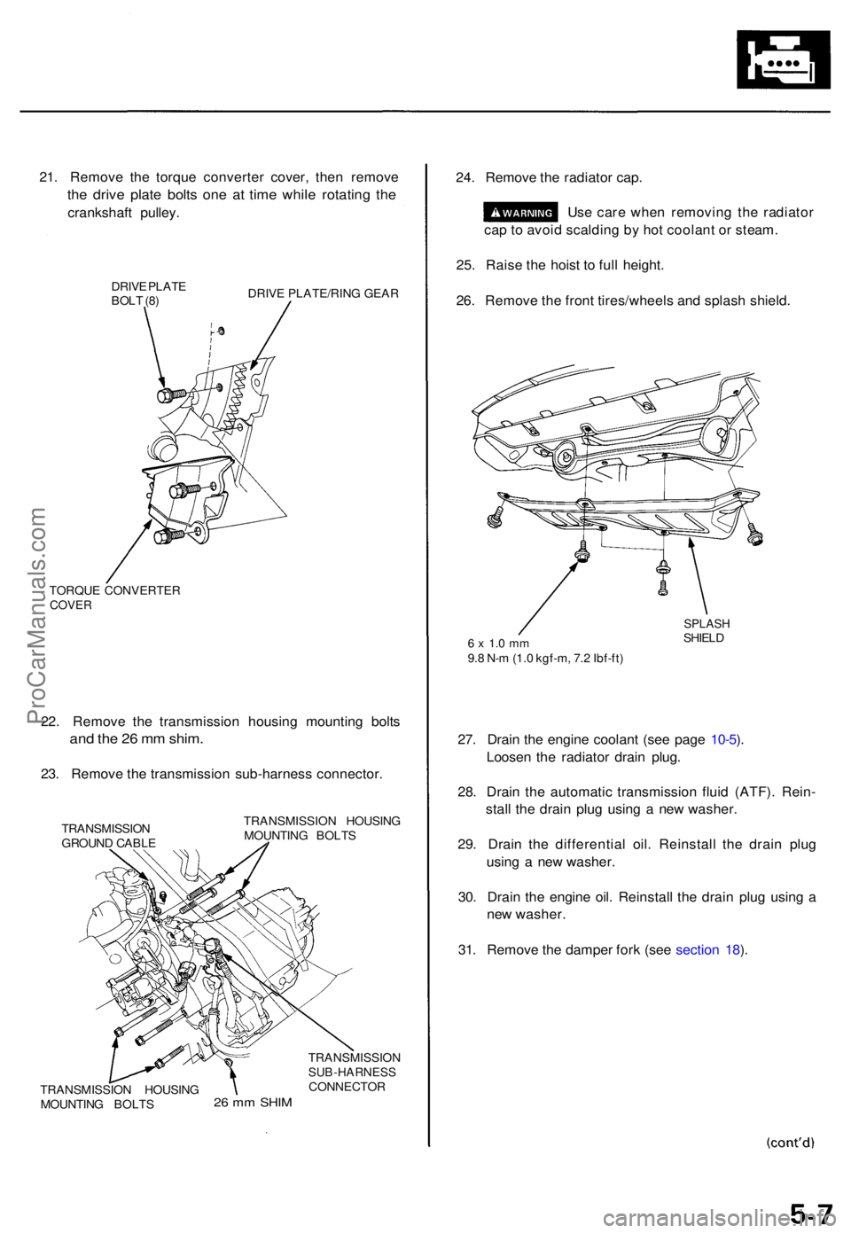
21. Remov e th e torqu e converte r cover , the n remov e
the driv e plat e bolt s on e a t tim e whil e rotatin g th e
crankshaf t pulley .
DRIVE PLAT E
BOL T (8 ) DRIV
E PLATE/RIN G GEA R
TORQU E CONVERTE R
COVER
22. Remov e th e transmissio n housin g mountin g bolt s
and th e 2 6 m m shim .
23. Remov e th e transmissio n sub-harnes s connector .
TRANSMISSIO N
GROUN D CABL E TRANSMISSIO
N HOUSIN G
MOUNTIN G BOLT S
24. Remov e th e radiato r cap .
Us e car e whe n removin g th e radiato r
ca p to avoi d scaldin g b y ho t coolan t o r steam .
25 . Rais e th e hois t t o ful l height .
26 . Remov e th e fron t tires/wheel s an d splas h shield .
6 x 1. 0 m m9.8 N- m (1. 0 kgf-m , 7. 2 Ibf-ft )
SPLAS HSHIELD
27. Drai n th e engin e coolan t (se e pag e 10-5 ).
Loose n th e radiato r drai n plug .
28 . Drai n th e automati c transmissio n flui d (ATF) . Rein -
stal l th e drai n plu g usin g a ne w washer .
29 . Drai n th e differentia l oil . Reinstal l th e drai n plu g
usin g a ne w washer .
30 . Drai n th e engin e oil . Reinstal l th e drai n plu g usin g a
ne w washer .
31 . Remov e th e dampe r for k (se e sectio n 18 ).
2 6 m m SHI M
TRANSMISSIO NSUB-HARNESSCONNECTOR
TRANSMISSIO N HOUSIN G
MOUNTIN G BOLT S
ProCarManuals.com
Page 758 of 1771
7. If the camshaft-to-holder oil clearance is out of tol-
erance:
— And the camshaft has already been replaced, you
must replace the cylinder head.
— If the camshaft has not been replaced, first check
the total runout with the camshaft supported on
V-blocks.
Camshaft Total Runout:
Standard (New): 0.03 mm (0.001 in) max.
Service Limit: 0.04 mm (0.002 in)
Rotate camshaft
while measuring.
If the total runout of the camshaft is within toler-
ance, replace the cylinder head.
If the total runout is out of tolerance, replace the
camshaft and recheck. If the oil clearance is still
out of tolerance, replace the cylinder head.
8. Check the cam lobe height wear.
Cam Lobe Height Standard (New):
INTAKE: 39.203 mm (1.5434 in)
EXHAUST: 38.875 mm (1.5305 in)
Check this area for wear.ProCarManuals.com
Page 762 of 1771
Cylinder Hea d
Warpag e
NOTE: I f th e camshaft-to-holde r oi l clearanc e (se e
pag e 6-22 ) i s no t withi n specifications , th e cylinde r hea d
canno t b e resurfaced .
I f th e camshaft-to-holde r oi l clearanc e i s withi n specifi -
cations , chec k th e cylinde r hea d fo r warpage .
• I f warpag e i s les s tha n 0.0 5 m m (0.00 2 in ) cylin -
de r hea d resurfacin g i s no t required .
• I f warpag e i s betwee n 0.0 5 m m (0.00 2 in ) an d
0. 2 m m (0.00 8 in) , resurfac e th e cylinde r head .
• Maximu m resurfac e limi t i s 0. 2 m m (0.00 8 in )
base d o n a heigh t o f 10 0 m m (3.9 4 in) .
PRECISIO N STRAIGH T EDG E
Measur e alon g edges , an d thre e way s acros s cen -
ter.
Cylinde r Hea d Height :
Standar d (New) : 99.9 5 - 100.0 5 m m
(3.93 5 - 3.93 9 in )
ProCarManuals.com
Page 764 of 1771

Valve Seat s
Reconditionin g
1.
2 .
3.
4 .
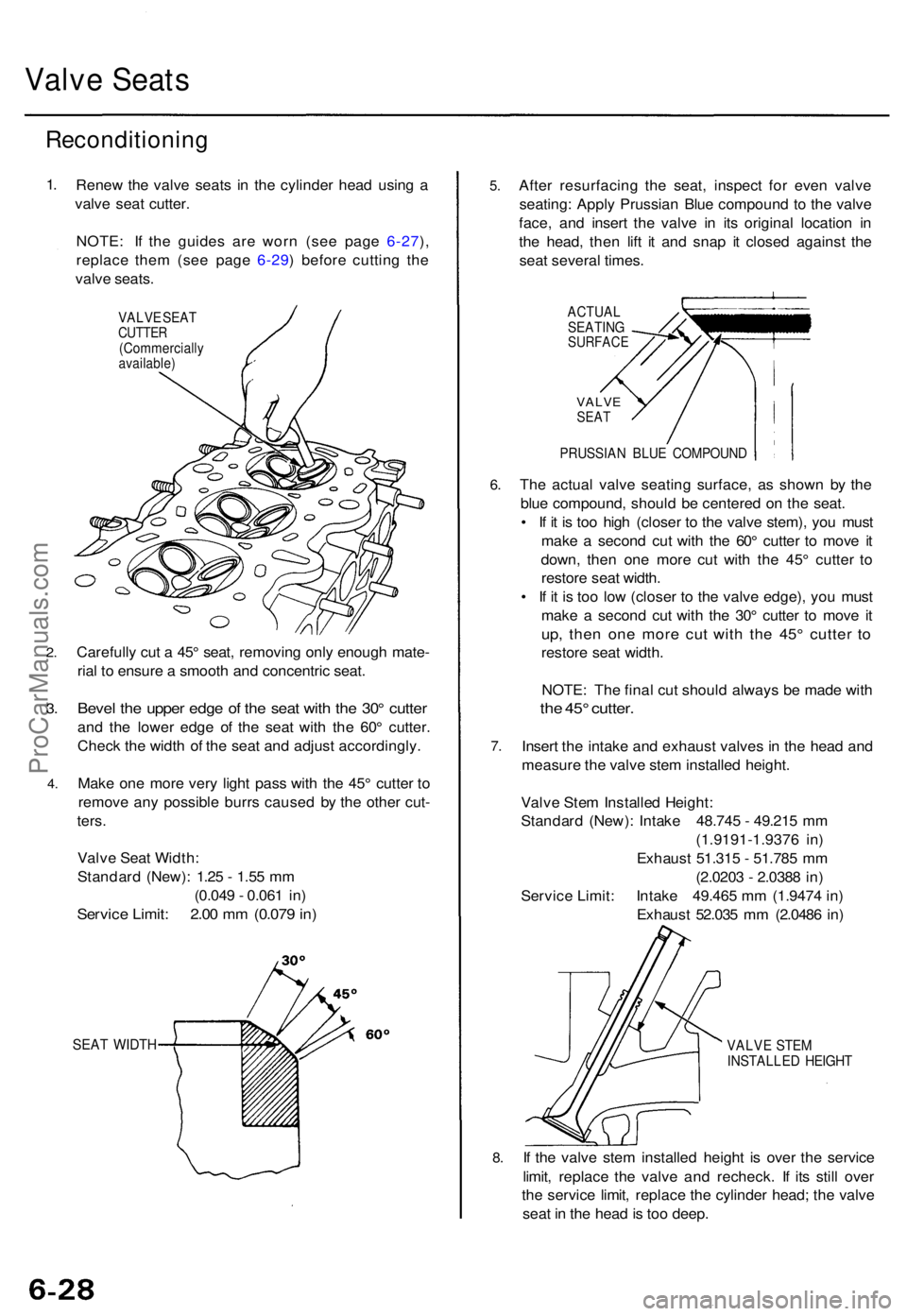
Rene w th e valv e seat s i n th e cylinde r hea d usin g a
valv e sea t cutter .
NOTE : I f th e guide s ar e wor n (se e pag e 6-27 ),
replac e the m (se e pag e 6-29 ) befor e cuttin g th e
valv e seats .
VALV E SEA TCUTTE R(Commerciall yavailable)
Carefully cu t a 45 ° seat , removin g onl y enoug h mate -
ria l t o ensur e a smoot h an d concentri c seat .
Beve l th e uppe r edg e o f th e sea t wit h th e 30 ° cutte r
and th e lowe r edg e o f th e sea t wit h th e 60 ° cutter .
Chec k th e widt h o f th e sea t an d adjus t accordingly .
Mak e on e mor e ver y ligh t pas s wit h th e 45 ° cutte r t o
remov e an y possibl e burr s cause d b y th e othe r cut -
ters .
Valv e Sea t Width :
Standar d (New) : 1.2 5 - 1.5 5 m m
(0.04 9 - 0.06 1 in )
Servic e Limit : 2.0 0 m m (0.07 9 in )
SEA T WIDT H
5.
6.
7 .
8.
Afte r resurfacin g th e seat , inspec t fo r eve n valv e
seating : Appl y Prussia n Blu e compoun d t o th e valv e
face , an d inser t th e valv e i n it s origina l locatio n i n
th e head , the n lif t i t an d sna p i t close d agains t th e
sea t severa l times .
ACTUA L
SEATIN G
SURFAC E
VALVESEAT
PRUSSIA N BLU E COMPOUN D
The actua l valv e seatin g surface , a s show n b y th e
blu e compound , shoul d b e centere d o n th e seat .
• I f i t i s to o hig h (close r t o th e valv e stem) , yo u mus t
mak e a secon d cu t wit h th e 60 ° cutte r t o mov e i t
down , the n on e mor e cu t wit h th e 45 ° cutte r t o
restor e sea t width .
• I f i t i s to o lo w (close r t o th e valv e edge) , yo u mus t
mak e a secon d cu t wit h th e 30 ° cutte r t o mov e i t
up , the n on e mor e cu t wit h th e 45 ° cutte r t o
restor e sea t width .
NOTE : Th e fina l cu t shoul d alway s b e mad e wit h
the 45 ° cutter .
Insert th e intak e an d exhaus t valve s i n th e hea d an d
measur e th e valv e ste m installe d height .
Valv e Ste m Installe d Height :
Standar d (New) : Intak e 48.74 5 - 49.21 5 m m
(1.9191-1.937 6 in )
Exhaus t 51.31 5 - 51.78 5 m m
(2.020 3 - 2.038 8 in )
Servic e Limit : Intak e 49.46 5 m m (1.947 4 in )
Exhaus t 52.03 5 m m (2.048 6 in )
VALV E STE M
INSTALLE D HEIGH T
If th e valv e ste m installe d heigh t i s ove r th e servic e
limit , replac e th e valv e an d recheck . I f it s stil l ove r
th e servic e limit , replac e th e cylinde r head ; th e valv e
sea t i n th e hea d is to o deep .
ProCarManuals.com
Page 766 of 1771
Valve Guide s
Replacemen t (cont'd )
7. Appl y a thi n coa t o f clea n engin e oi l t o th e outsid e
of th e ne w valv e guide . Instal l th e guid e fro m th e
camshaf t sid e o f th e head ; us e th e specia l too l t o
driv e th e guid e i n t o th e specifie d installe d height . I f
yo u hav e al l 2 0 guide s t o do , yo u ma y hav e to rehea t
th e head .
VALV E GUID EDRIVER , 5. 5 m m07742-001010 0
Valve Guid e Installe d Height :
Intake : 24.7 5 - 25.2 5 m m (0.97 4 - 0.99 4 in )
Exhaust : 16.0 5 - 16.5 5 m m (0.63 2 - 0.65 2 in )
ProCarManuals.com