1995 ACURA TL wheel torque
[x] Cancel search: wheel torquePage 667 of 1771
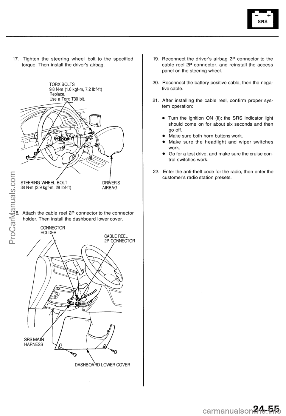
17. Tighten the steering wheel bolt to the specified
torque. Then install the driver's airbag.
TORX BOLTS
9.8 N-m (1.0 kgf-m, 7.2 Ibf-ft)
Replace.
Use a Torx T30 bit.
STEERING WHEEL BOLT
38 N-m (3.9 kgf-m, 28 Ibf-ft)
DRIVER'S
AIRBAG
18. Attach the cable reel 2P connector to the connector
holder. Then install the dashboard lower cover.
CONNECTOR
HOLDER
CABLE REEL
2P CONNECTOR
SRS
MAIN
HARNESS
DASHBOARD LOWER COVER
19. Reconnect the driver's airbag 2P connector to the
cable reel 2P connector, and reinstall the access
panel on the steering wheel.
20. Reconnect the battery positive cable, then the nega-
tive cable.
21. After installing the cable reel, confirm proper sys-
tem operation:
Turn the ignition ON (II); the SRS indicator light
should come on for about six seconds and then
go
off.
Make sure both horn buttons work.
Make sure the headlight and wiper switches
work.
Go for a test drive, and make sure the cruise con-
trol switches work.
22. Enter the anti-theft code for the radio, then enter the
customer's radio station presets.ProCarManuals.com
Page 781 of 1771
Main Bearings
Clearance
1. To check main bearing-to-journal oil clearance,
remove the main caps and bearing halves.
2. Clean each main journal and bearing half with a
clean shop towel.
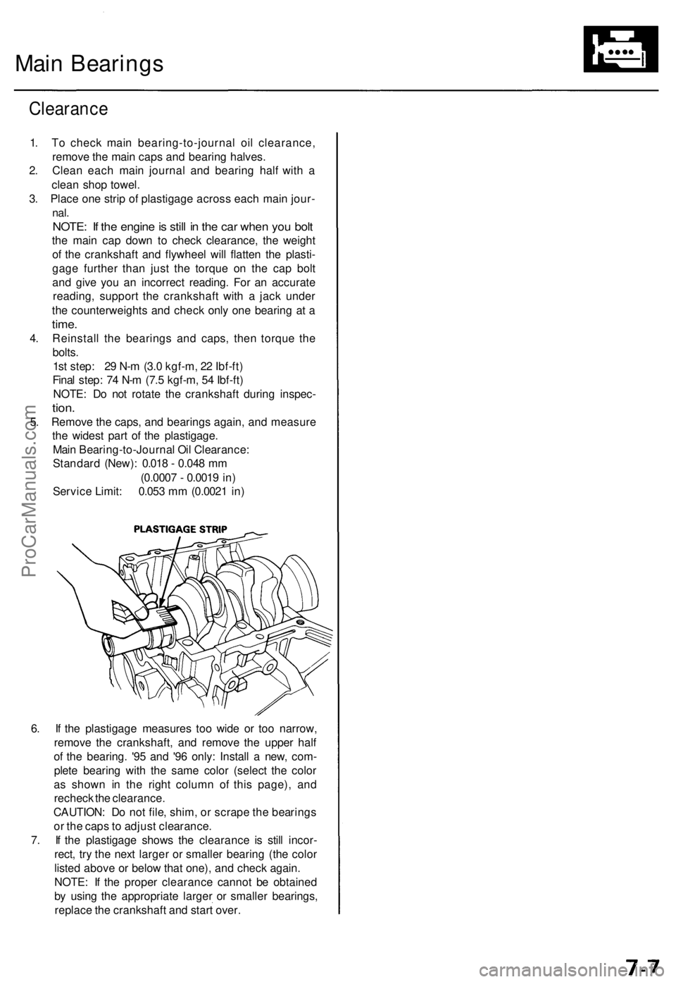
3. Place one strip of plastigage across each main jour-
nal.
NOTE: If the engine is still in the car when you bolt
the main cap down to check clearance, the weight
of the crankshaft and flywheel will flatten the plasti-
gage further than just the torque on the cap bolt
and give you an incorrect reading. For an accurate
reading, support the crankshaft with a jack under
the counterweights and check only one bearing at a
time.
4. Reinstall the bearings and caps, then torque the
bolts.
1st step: 29 N-m (3.0 kgf-m, 22 Ibf-ft)
Final step: 74 N-m (7.5 kgf-m, 54 Ibf-ft)
NOTE: Do not rotate the crankshaft during inspec-
tion.
5. Remove the caps, and bearings again, and measure
the widest part of the plastigage.
Main Bearing-to-Journal Oil Clearance:
Standard (New): 0.018 - 0.048 mm
(0.0007 - 0.0019 in)
Service Limit: 0.053 mm (0.0021 in)
6. If the plastigage measures too wide or too narrow,
remove the crankshaft, and remove the upper half
of the bearing. '95 and '96 only: Install a new, com-
plete bearing with the same color (select the color
as shown in the right column of this page), and
recheck the clearance.
CAUTION: Do not file, shim, or scrape the bearings
or the caps to adjust clearance.
7. If the plastigage shows the clearance is still incor-
rect, try the next larger or smaller bearing (the color
listed above or below that one), and check again.
NOTE: If the proper clearance cannot be obtained
by using the appropriate larger or smaller bearings,
replace the crankshaft and start over.ProCarManuals.com
Page 936 of 1771

Description
The automatic transmission is a combination of a 3-element torque converter and a dual-shaft electronically controlled
automatic transmission which provides 4 speeds forward and 1 reverse. The entire unit is positioned in line with the engine.
Torque Converter, Gears and Clutches
The torque converter consists of a pump, turbine and stator, assembled in a single unit.
They are connected to the engine crankshaft so they turn together as a unit as the engine turns.
Around the outside of the drive plate is a ring gear which meshes with the starter pinion when the engine is being started.
The entire torque converter assembly serves as a flywheel while transmitting power to the transmission mainshaft.
The transmission has two parallel shafts: the mainshaft and the countershaft. The mainshaft is in line with the engine
crankshaft.
The mainshaft includes the 1st, 2nd and 4th clutches, and gears for 4th, 2nd, 1st and reverse (3rd gear is integral with the
mainshaft, while the reverse gear is integral with 4th gear).
The countershaft includes the 3rd, and 1st-hold clutches, and gears for 3rd, 4th, 1st, 2nd, reverse, and parking. The sec-
ondary drive gear is integrated with the countershaft.
The gears on the mainshaft are in constant mesh with those on the countershaft.
When certain combinations of gears in the transmission are engaged by clutches, power is transmitted from the mainshaft
to the countershaft to provide and positions.
Electronic Control
The electronic control system consists of the Transmission Control Module (TCM), sensors, a linear solenoid and four
solenoid valves. Shifting and lock-up are electronically controlled for comfortable driving under all conditions.
The TCM is located below the dashboard, behind the glove box on the passenger's side.
Hydraulic Control
The lower valve body assembly includes the main valve body, the servo body and the shift control solenoid valves. They
are bolted on the lower part of the transmission housing.
Other valve bodies, the regulator valve body, the ATF pump body, the 2nd accumulator body, and the throttle valve body,
are bolted to the torque converter housing.
The main valve body contains the manual valve, the 1 - 2 shift valve, the 2 - 3 shift valve, the 3 - 4 shift valve, the 4th kick-
down valve, the 2 - 3 orifice control valve, the 3 - 4 orifice control valve, the 4th exhaust valve, the servo control valve,
and the main orifice control valve.
The servo body contains the servo valve, 3rd and 4th accumulator pistons.
The regulator valve body contains the regulator valve, the lock-up shift valve, and the cooler relief valve.
Fluid from the regulator passes through the manual valve to the various control valves.
The throttle valve body includes the throttle valve which is bolted onto the 2nd accumulator body. The 2nd accumulator
piston is assembled in the 2nd accumulator body.
The linear solenoid is joined with the throttle valve body.
The ATF pump body contains the modulator valve, the lock-up control valve, the lock-up timing valve, and the relief valve.
The torque converter check valve is located in the torque converter housing under the ATF pump body.
The 1st and 1st-hold accumulator pistons are assembled in the rear cover.
The clutches receive fluid from their respective feed pipes or internal hydraulic circuit.
Shift Control Mechanism
Input from various sensors located throughout the vehicle determines which shift control solenoid valve the TCM will acti-
vate. Activating a shift control solenoid valve changes modulator pressure, causing a shift valve to move. This pressurizes
a line to one of the clutches, engaging that clutch and its corresponding gear.
Lock-up Mechanism
In position, in 2nd, 3rd and 4th, and in position in 3rd, pressurized fluid is drained from the back of the torque con-
verter through a fluid passage, causing the lock-up piston to be held against the torque converter cover. As this takes place,
the mainshaft rotates at the same speed as the engine crankshaft. Together with hydraulic control, the TCM optimizes the
timing of the lock-up mechanism. The lock-up valves control the range of lock-up according to lock-up control solenoid
valves A and B, and throttle valve. When lock-up control solenoid valves A and B activate, the modulator pressure changes.
The lock-up control solenoid valves A and B are mounted on the torque converter housing, and are controlled by the TCM.ProCarManuals.com
Page 944 of 1771

Position
The power flow when decelerating is as follows:
1. Rolling resistance from the road surface goes through the front wheels to the secondary drive gear, then to the coun-
tershaft 1st gear via the 1st-hold clutch which is applied during deceleration.
2. The one-way clutch disengages at this time because the application of torque is reversed.
3. The counterforce conveyed to the countershaft 1st gear turns the mainshaft 1st gear. At this time, since hydraulic
pressure is also applied to the 1st clutch, counterforce is also transmitted to the mainshaft. As a result, engine braking
can be obtained with 1st gear.
TORQUE CONVERTER
MAINSHAFT 1ST GEAR
1ST CLUTCH
MAINSHAFT
SECONDARY
DRIVE GEAR
COUNTERSHAFT
1ST-HOLD
CLUTCH
COUNTERSHAFT
1ST GEAR
SECONDARY DRIVEN GEARProCarManuals.com
Page 997 of 1771
Pressure Testin g
While testing , b e carefu l o f th e rotatin g fron t wheels .
Mak e sur e lifts , jack s an d safet y stand s ar e place d
properl y (se e sectio n 1 ).
CAUTION :
Befor e testing , b e sur e th e transmissio n flui d is fille d
t o th e prope r level .
War m u p th e engin e befor e testing .
1. Rais e th e fron t o f th e vehicle , an d suppor t i t wit h
safet y stand s (se e sectio n 1 ).
2 . Se t th e parkin g brake , an d bloc k bot h rea r wheel s
securely .
3. Allo w th e fron t wheel s t o rotat e freely .
4 . War m u p th e engin e (th e radiato r fa n come s on) ,
the n sto p an d connec t a tachometer .
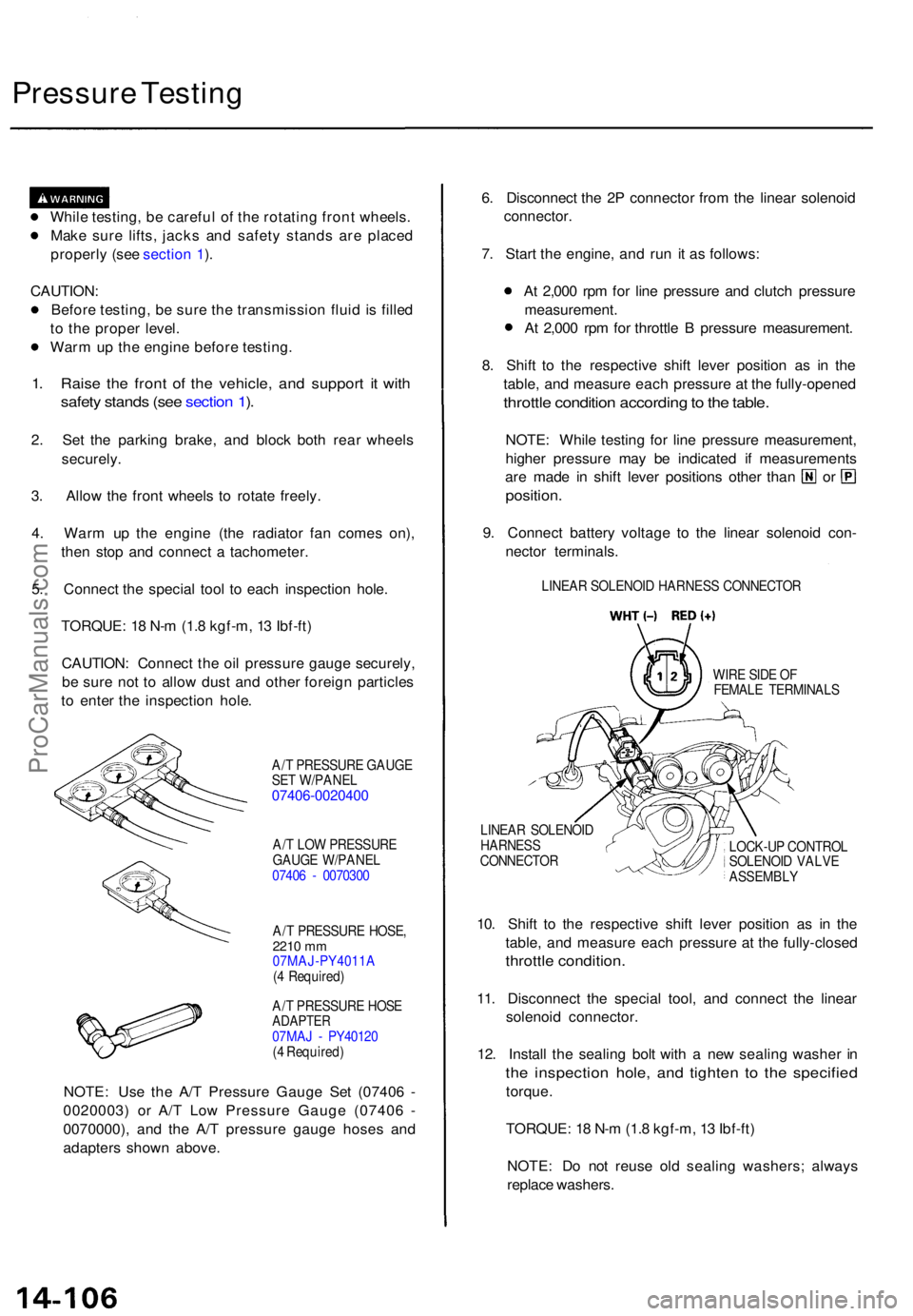
5 . Connec t th e specia l too l t o eac h inspectio n hole .
TORQUE : 1 8 N- m (1. 8 kgf-m , 1 3 Ibf-ft )
CAUTION : Connec t th e oi l pressur e gaug e securely ,
b e sur e no t t o allo w dus t an d othe r foreig n particle s
t o ente r th e inspectio n hole .
A/T PRESSUR E GAUG E
SE T W/PANE L
07406-002040 0
A/T LO W PRESSUR E
GAUG E W/PANE L
0740 6 - 007030 0
A/ T PRESSUR E HOSE ,
2210 mm07MAJ-PY4011 A
( 4 Required )
A/ T PRESSUR E HOS E
ADAPTE R07MAJ - PY4012 0
( 4 Required )
NOTE: Us e th e A/ T Pressur e Gaug e Se t (0740 6 -
0020003 ) o r A/ T Lo w Pressur e Gaug e (0740 6 -
0070000) , an d th e A/ T pressur e gaug e hose s an d
adapter s show n above . 6
. Disconnec t th e 2 P connecto r fro m th e linea r solenoi d
connector .
7 . Star t th e engine , an d ru n i t a s follows :
A t 2,00 0 rp m fo r lin e pressur e an d clutc h pressur e
measurement .
A t 2,00 0 rp m fo r throttl e B pressur e measurement .
8 . Shif t t o th e respectiv e shif t leve r positio n a s i n th e
table , an d measur e eac h pressur e a t th e fully-opene d
throttle conditio n accordin g to th e table .
NOTE : Whil e testin g fo r lin e pressur e measurement ,
highe r pressur e ma y b e indicate d i f measurement s
are mad e i n shif t leve r position s othe r tha n o r
position .
9. Connec t batter y voltag e t o th e linea r solenoi d con -
necto r terminals .
LINEAR SOLENOI D HARNES S CONNECTO R
WIR E SID E O F
FEMAL E TERMINAL S
LINEA R SOLENOI D
HARNES S
CONNECTO R LOCK-U
P CONTRO L
SOLENOI D VALV E
ASSEMBL Y
10. Shif t t o th e respectiv e shif t leve r positio n a s i n th e
table , an d measur e eac h pressur e a t th e fully-close d
throttle condition .
11. Disconnec t th e specia l tool , an d connec t th e linea r
solenoi d connector .
12 . Instal l th e sealin g bol t wit h a ne w sealin g washe r i n
th e inspectio n hole , an d tighte n t o th e specifie d
torque.
TORQUE : 1 8 N- m (1. 8 kgf-m , 1 3 Ibf-ft )
NOTE : D o no t reus e ol d sealin g washers ; alway s
replac e washers .
ProCarManuals.com
Page 1213 of 1771
Steering Gearbo x
Installatio n (cont'd )
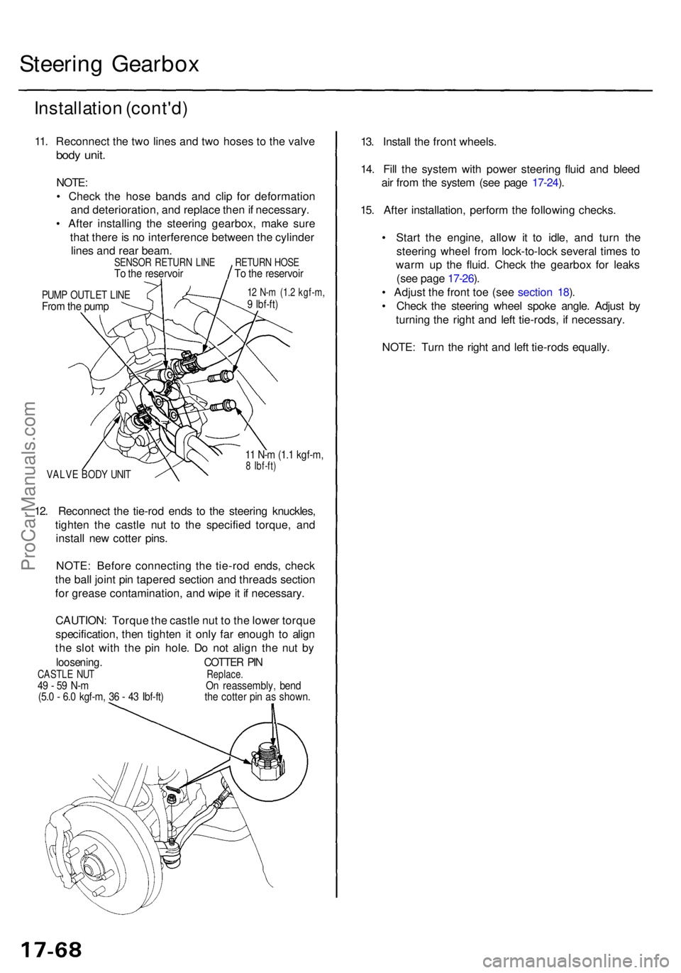
11. Reconnec t th e tw o line s an d tw o hose s t o th e valv e
body unit .
NOTE :
• Chec k th e hos e band s an d cli p fo r deformatio n
an d deterioration , an d replac e the n if necessary .
• Afte r installin g th e steerin g gearbox , mak e sur e
tha t ther e is n o interferenc e betwee n th e cylinde r
line s an d rea r beam .
PUMP OUTLE T LIN EFrom th e pum p
12 N- m (1. 2 kgf-m ,9 Ibf-ft )
VALV E BOD Y UNI T
11 N- m (1. 1 kgf-m ,8 Ibf-ft )
12. Reconnec t th e tie-ro d end s t o th e steerin g knuckles ,
tighte n th e castl e nu t t o th e specifie d torque , an d
instal l ne w cotte r pins .
NOTE : Befor e connectin g th e tie-ro d ends , chec k
th e bal l join t pi n tapere d sectio n an d thread s sectio n
fo r greas e contamination , an d wip e it i f necessary .
CAUTION : Torqu e th e castl e nu t t o th e lowe r torqu e
specification , the n tighte n it onl y fa r enoug h t o alig n
th e slo t wit h th e pi n hole . D o no t alig n th e nu t b y
loosening . COTTER PI NCASTL E NU T Replace.49 - 5 9 N- m O n reassembly , ben d(5.0 - 6. 0 kgf-m , 3 6 - 4 3 Ibf-ft ) th e cotte r pi n a s shown .
13. Instal l th e fron t wheels .
14 . Fil l th e syste m wit h powe r steerin g flui d an d blee d
ai r fro m th e syste m (se e pag e 17-24 ).
15 . Afte r installation , perfor m th e followin g checks .
• Star t th e engine , allo w i t t o idle , an d tur n th e
steerin g whee l fro m lock-to-loc k severa l time s t o
war m u p th e fluid . Chec k th e gearbo x fo r leak s
(se e pag e 17-26 ).
• Adjus t th e fron t to e (se e sectio n 18 ).
• Chec k th e steerin g whee l spok e angle . Adjus t b y
turnin g th e righ t an d lef t tie-rods , i f necessary .
NOTE : Tur n th e righ t an d lef t tie-rod s equally .
SENSO R RETUR N LIN ETo th e reservoi rRETURN HOS ETo th e reservoi r
ProCarManuals.com
Page 1218 of 1771
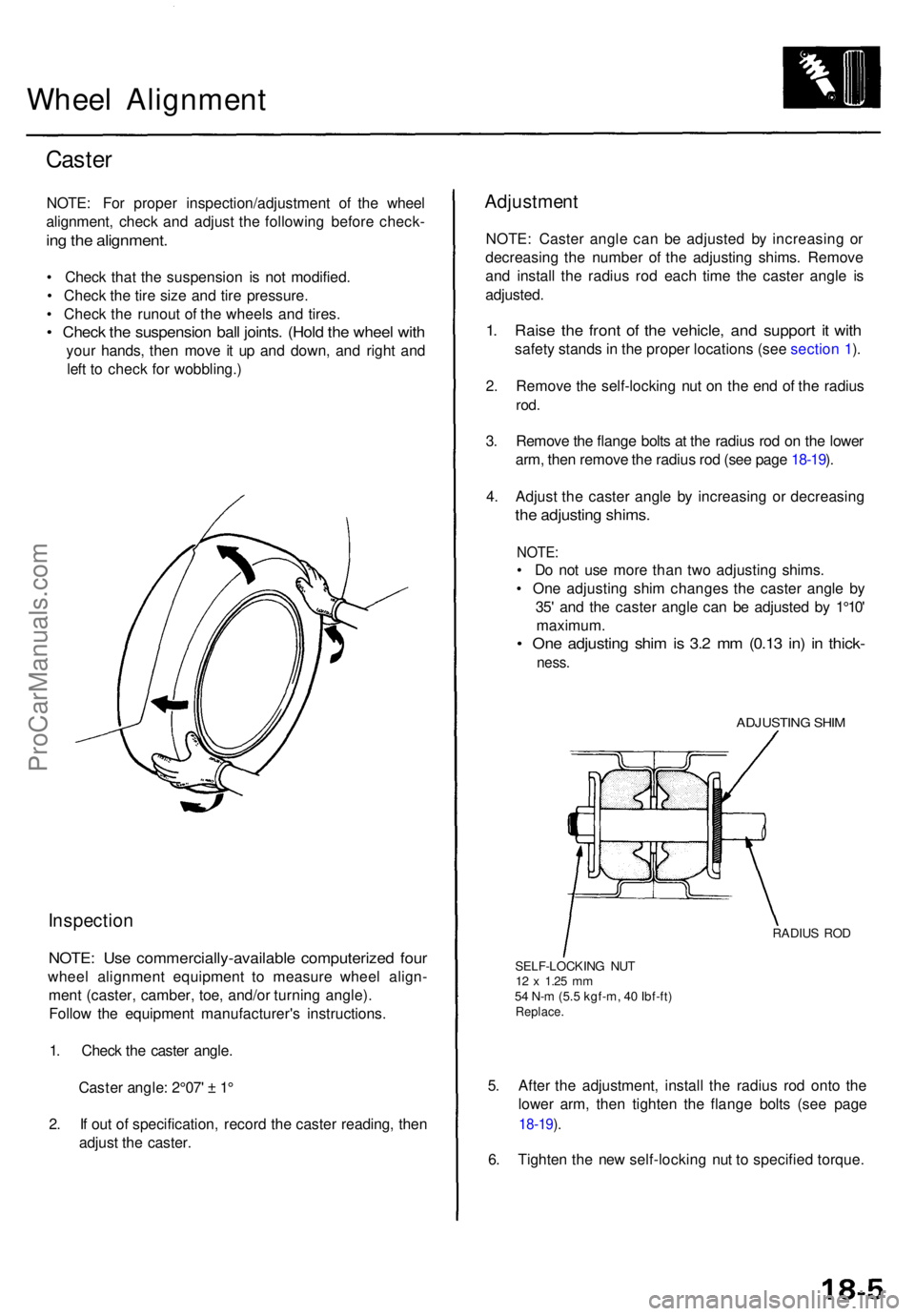
Wheel Alignmen t
Caster
NOTE : Fo r prope r inspection/adjustmen t o f th e whee l
alignment , chec k an d adjus t th e followin g befor e check -
ing th e alignment .
• Chec k tha t th e suspensio n i s no t modified .
• Chec k th e tir e siz e an d tir e pressure .
• Chec k th e runou t o f th e wheel s an d tires .
• Chec k th e suspensio n bal l joints . (Hol d th e whee l wit h
you r hands , the n mov e i t u p an d down , an d righ t an d
lef t t o chec k fo r wobbling. )
Inspection
NOTE: Us e commercially-availabl e computerize d fou r
whee l alignmen t equipmen t t o measur e whee l align -
men t (caster , camber , toe , and/o r turnin g angle) .
Follo w th e equipmen t manufacturer' s instructions .
1 . Chec k th e caste r angle .
Caste r angle : 2°07 ' ± 1 °
2 . I f ou t o f specification , recor d th e caste r reading , the n
adjus t th e caster .
Adjustmen t
NOTE: Caste r angl e ca n b e adjuste d b y increasin g o r
decreasin g th e numbe r o f th e adjustin g shims . Remov e
an d instal l th e radiu s ro d eac h tim e th e caste r angl e i s
adjusted .
1. Rais e th e fron t o f th e vehicle , an d suppor t i t wit h
safet y stand s in th e prope r location s (se e sectio n 1 ).
2 . Remov e th e self-lockin g nu t o n th e en d o f th e radiu s
rod.
3. Remov e th e flang e bolt s a t th e radiu s ro d o n th e lowe r
arm , the n remov e th e radiu s ro d (se e pag e 18-19 ).
4 . Adjus t th e caste r angl e b y increasin g o r decreasin g
the adjustin g shims .
NOTE:
• D o no t us e mor e tha n tw o adjustin g shims .
• On e adjustin g shi m change s th e caste r angl e b y
35 ' an d th e caste r angl e ca n b e adjuste d b y 1°10 '
maximum .
• On e adjustin g shi m is 3. 2 m m (0.1 3 in ) i n thick -
ness.
ADJUSTIN G SHI M
RADIU S RO D
SELF-LOCKIN G NU T
12 x 1.2 5 mm54 N- m (5. 5 kgf-m , 4 0 Ibf-ft )Replace .
5. Afte r th e adjustment , instal l th e radiu s ro d ont o th e
lowe r arm , the n tighte n th e flang e bolt s (se e pag e
18-19 ).
6 . Tighte n th e ne w self-lockin g nu t t o specifie d torque .
ProCarManuals.com
Page 1247 of 1771
Rear Dampe r
Installatio n
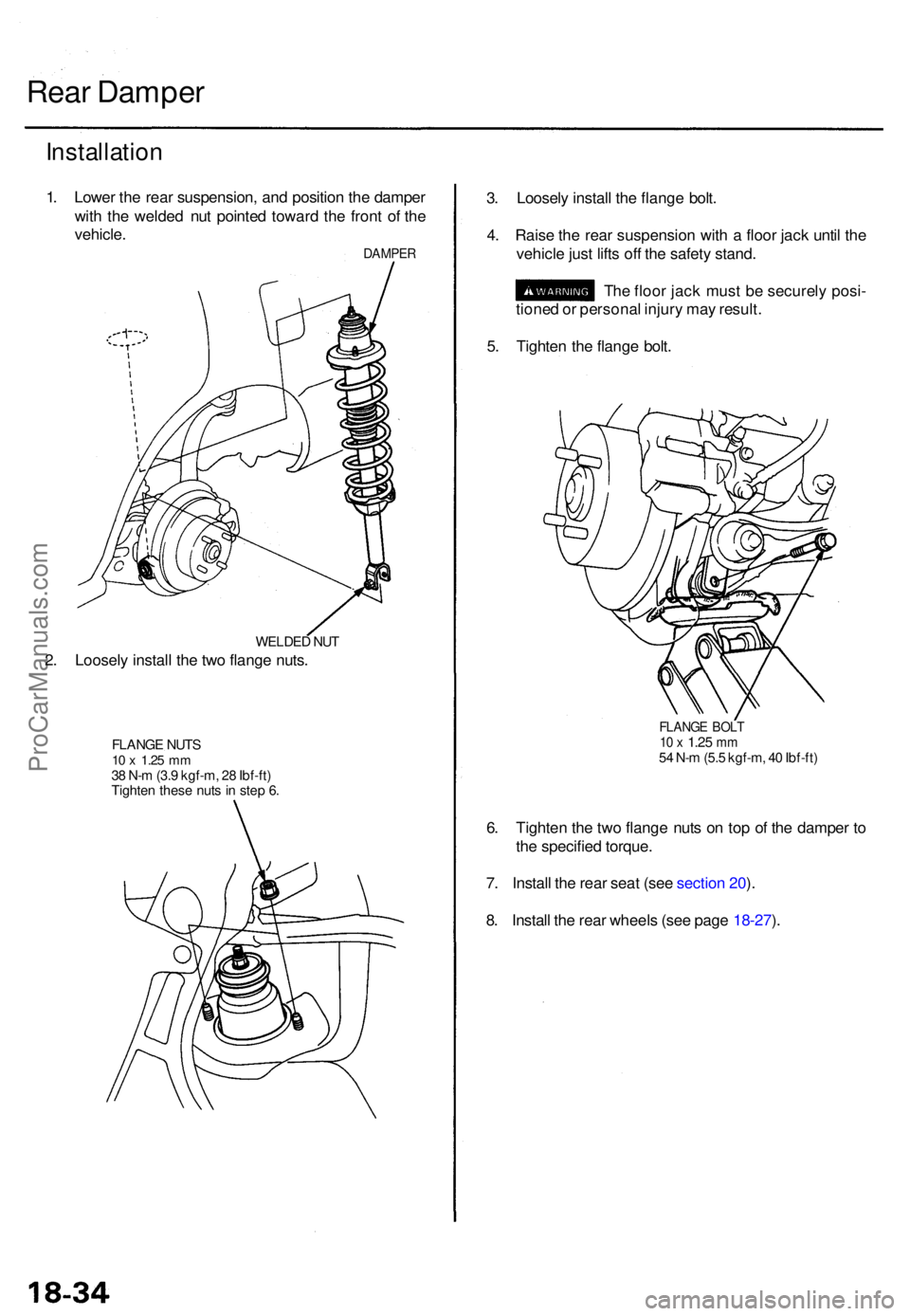
1. Lowe r th e rea r suspension , an d positio n th e dampe r
wit h th e welde d nu t pointe d towar d th e fron t o f th e
vehicle .
DAMPE R
WELDED NU T
2. Loosel y instal l th e tw o flang e nuts .
FLANG E NUT S10 x 1.2 5 mm38 N- m (3. 9 kgf-m , 2 8 Ibf-ft )
Tighte n thes e nut s i n ste p 6 .
3. Loosel y instal l th e flang e bolt .
4 . Rais e th e rea r suspensio n wit h a floo r jac k unti l th e
vehicl e jus t lift s of f th e safet y stand .
Th e floo r jac k mus t b e securel y posi -
tione d o r persona l injur y ma y result .
5 . Tighte n th e flang e bolt .
FLANG E BOL T10 x 1.2 5 mm54 N- m (5. 5 kgf-m , 4 0 Ibf-ft )
6. Tighte n th e tw o flang e nut s o n to p o f th e dampe r t o
th e specifie d torque .
7 . Instal l th e rea r sea t (se e sectio n 20 ).
8 . Instal l th e rea r wheel s (se e pag e 18-27 ).
ProCarManuals.com