Page 1086 of 1708
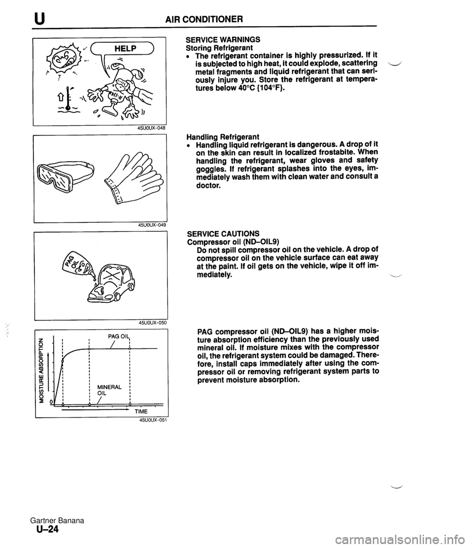
u AIR CONDITIONER SERVICE WARNINGS Storing Refrigerant The refrigerant container is highly pressurized. If it is subjected to high heat, it could explode, scattering u metal fragments and liquid refrigerant that can seri- ously injure you. Store the refrigerant at tempera- tures below 40°C (1 04°F). Handling Refrigerant Handling liquid refrigerant is dangerous. A drop of it on the skin can result in localized frostabite. When handling the refrigerant, wear gloves and safety goggles. If refrigerant splashes into the eyes, im- mediately wash them with clean water and consult a doctor. SERVICE CAUTIONS Compressor oil (ND-OILS) Do not spill compressor oil on the vehicle. A drop of compressor oil on the vehicle surface can eat away at the paint. If oil gets on the vehicle, wipe it off im- mediately. b PAG compressor oil (ND-OILS) has a higher mois- ture absorption efficiency than the previously used mineral oil. If moisture mixes with the compressor oil, the refrigerant system could be damaged. There- fore, install caps immediately after using the com- pressor oil or removing refrigerant system parts to prevent moisture absorption. Gartner Banana
Page 1087 of 1708
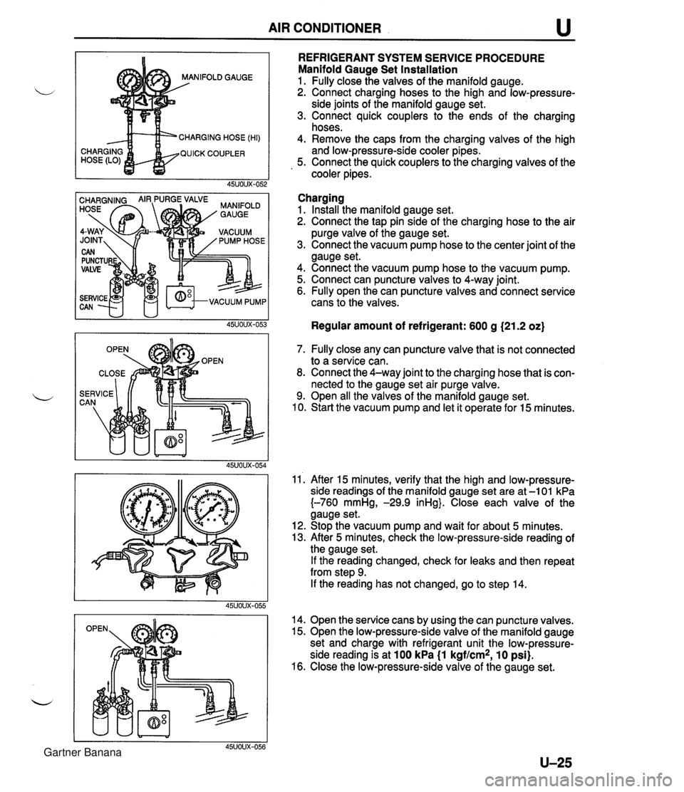
AIR CONDITIONER u NIFOLD GAUGE CHARGING HOSE (HI) QUICK COUPLER REFRIGERANT SYSTEM SERVICE PROCEDURE Manifold Gauge Set Installation 1. Fully close the valves of the manifold gauge. 2. Connect charging hoses to the high and low-pressure- side joints of the manifold gauge set. 3. Connect quick couplers to the ends of the charging hoses. 4. Remove the caps from the charging valves of the high and low-pressure-side cooler pipes. 5. Connect the quick couplers to the charging valves of the cooler pipes. Charging 1. Install the manifold gauge set. 2. Connect the tap pin side of the charging hose to the air purge valve of the gauge set. 3. Connect the vacuum pump hose to the center joint of the gauge set. 4. Connect the vacuum pump hose to the vacuum pump. 5. Connect can puncture valves to 4-way joint. 6. Fully open the can puncture valves and connect service cans to the valves. Regular amount of refrigerant: 600 g (21.2 oz) 7. Fully close any can puncture valve that is not connected to a service can. 8. Connect the 4-way joint to the charging hose that is con- nected to the gauge set air purge valve. 9. Open all the valves of the manifold gauge set. 10. Start the vacuum pump and let it operate for 15 minutes. 11'. After 15 minutes, verify that the high and low-pressure- side readings of the manifold gauge set are at -1 01 kPa {-760 mmHg, -29.9 inHg}. Close each valve of the gauge set. 12. Stop the vacuum pump and wait for about 5 minutes. 13. After 5 minutes, check the low-pressure-side reading of the gauge set. If the reading changed, check for leaks and then repeat from step 9. If the reading has not changed, go to step 14. 14. Open the service cans by using the can puncture valves. 15. Open the low-pressure-side valve of the manifold gauge set and charge with refrigerant unit the low-pressure- side reading is at 100 kPa (1 kgf/cm2, 10 psi). 16. Close the low-pressure-side valve of the gauge set. Gartner Banana
Page 1089 of 1708
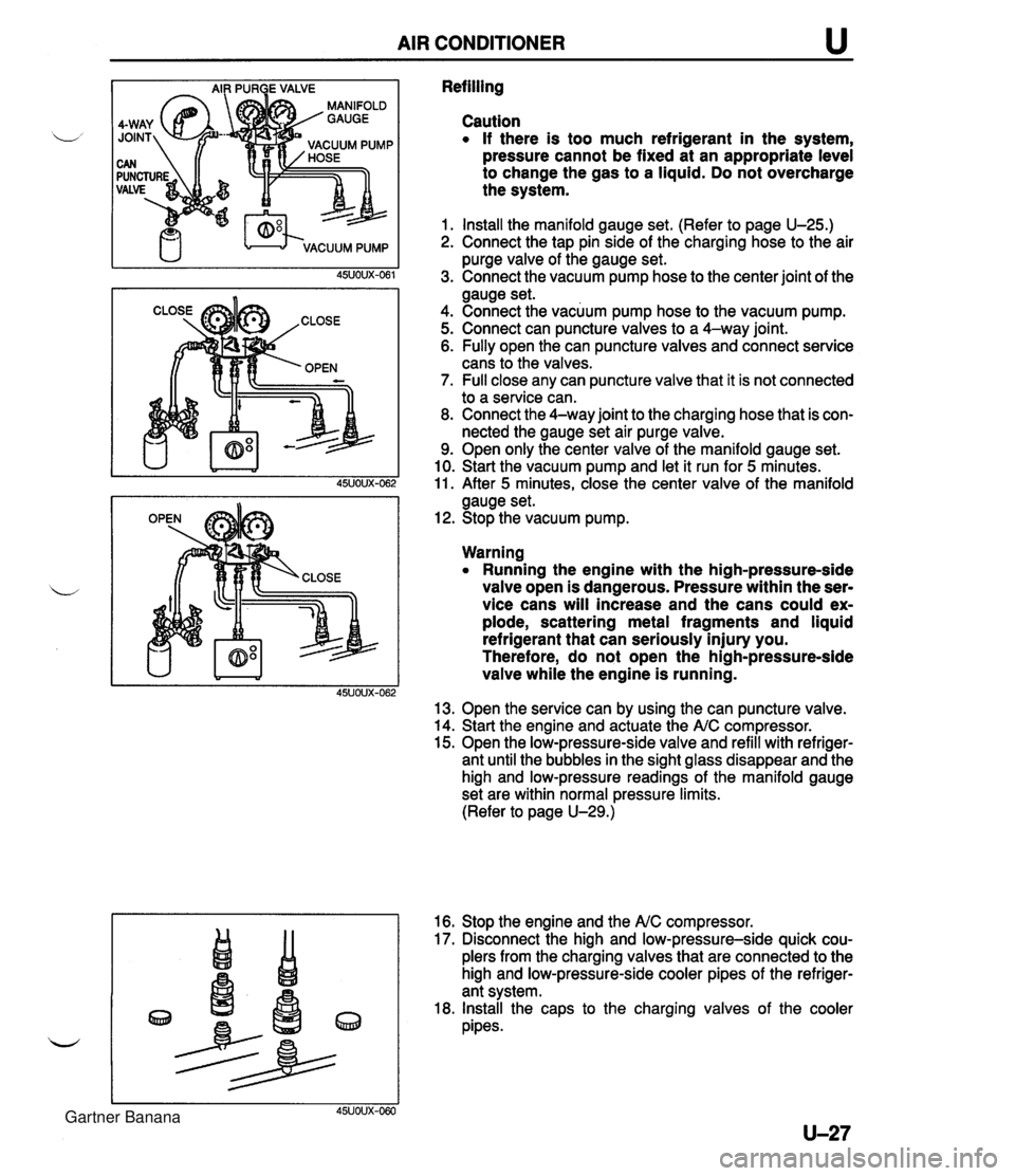
AIR CONDITIONER u Refilling Caution If there is too much refrigerant in the system, pressure cannot be fixed at an appropriate level to change the gas to a liquid. Do not overcharge the system. 1. Install the manifold gauge set. (Refer to page U-25.) 2. Connect the tap pin side of the charging hose to the air purge valve of the gauge set. 3. Connect the vacuum pump hose to the center joint of the gauge set. 4. Connect the vacuum pump hose to the vacuum pump. 5. Connect can puncture valves to a 4-way joint. 6. Fully open the can puncture valves and connect service cans to the valves. 7. Full close any can puncture valve that it is not connected to a service can. 8. Connect the 4-way joint to the charging hose that is con- nected the gauge set air purge valve. 9. Open only the center valve of the manifold gauge set. 10. Start the vacuum pump and let it run for 5 minutes. 11. After 5 minutes, close the center valve of the manifold gauge set. 12. Stop the vacuum pump. Warning Running the engine with the high-pressure-side valve open is dangerous. Pressure within the ser- vice cans will increase and the cans could ex- plode, scattering metal fragments and liquid refrigerant that can seriously injury you. Therefore, do not open the high-pressure-side valve while the engine is running. 13. Open the service can by using the can puncture valve. 14. Start the engine and actuate the A/C compressor. 15. Open the low-pressure-side valve and refill with refriger- ant until the bubbles in the sight glass disappear and the high and low-pressure readings of the manifold gauge set are within normal pressure limits. (Refer to page U-29.) 16. Stop the engine and the NC compressor. 17. Disconnect the high and low-pressure-side quick cou- plers from the charging valves that are connected to the high and low-pressure-side cooler pipes of the refriger- ant system. 18. Install the caps to the charging valves of the cooler pipes. 45UOUX-060 Gartner Banana
Page 1107 of 1708
AIR CONDITIONER u O-RING (2) Tighten the discharge valve body installation through bolts. Tightening torque: 10.8 N-m (110 kgf-cm, 95.5 in-lbf) (3) Tighten the discharge valve body installation bolts. Tightening torque: 10.8 N-m (110 kgf-cm, 95.5 in-lbf) 1 3. Pour compressor oil (ND-OILS) Pour compressor oil into the A/C compressor. Compressor oil amount: Same amount as drained, plus 20 ml(20 cc, 0.6 fl or) 14. Installation of service valve (1) Apply the compressor oil to the new O-rings. (2) Install the service valves to the compressor and tight- en the installation bolts. Tightening torque: 12.3 N-m (125 kgf-cm, 109 in-lbf) Gartner Banana
Page 1113 of 1708
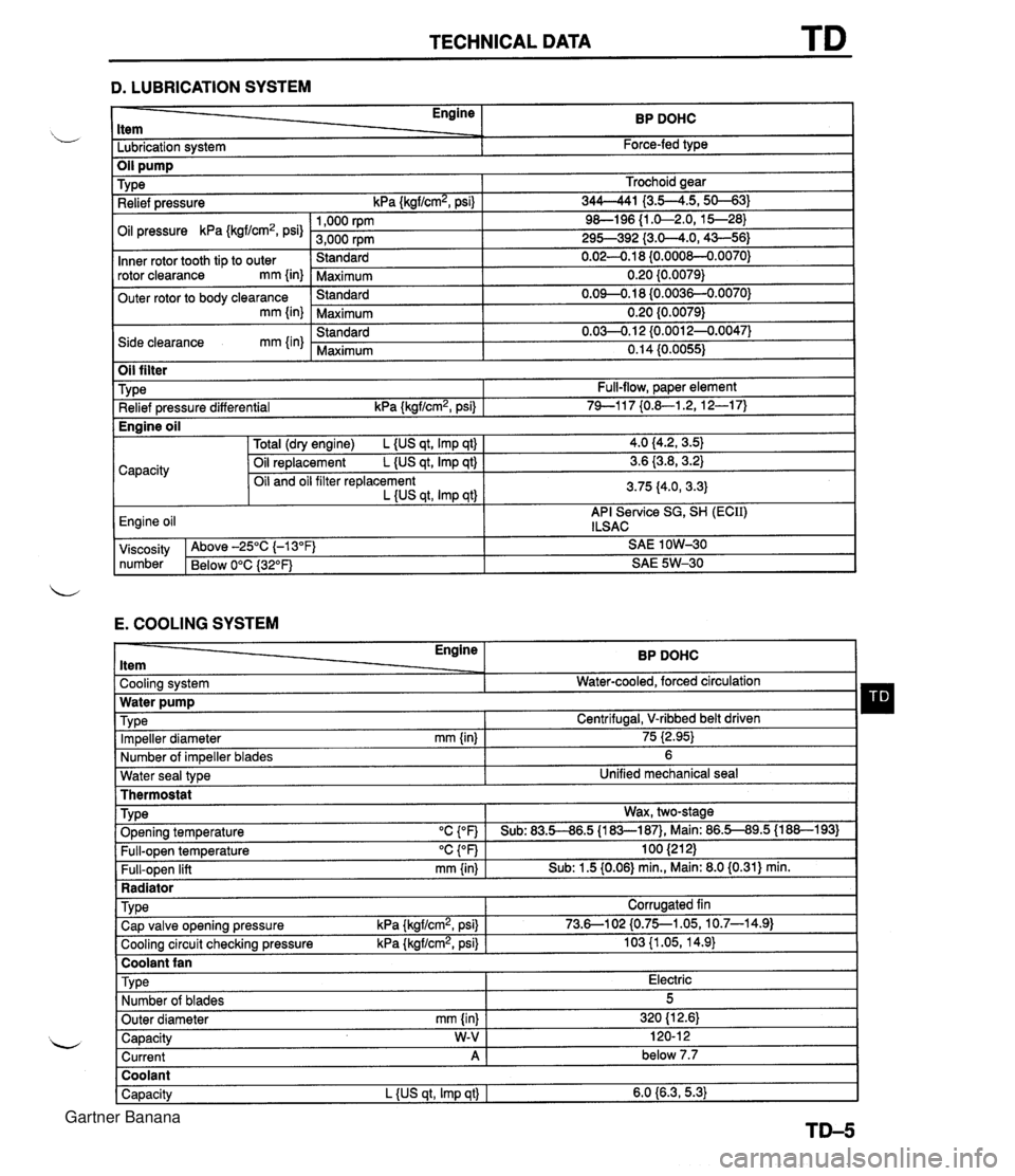
TECHNICAL DATA D. LUBRICATION SYSTEM - Engine ltem BP DOHC - -. Lubrication system Force-fed type E. COOLING SYSTEM Trochoid gear 344-41 I3.5--4.5,s-31 9&l96 {I .&2.0, 15--28) 295-392 {3.0-4.0,43-56) 0.02-0.1 8 {0.000&0.0070) 0.20 {0.0079) 0.09-0.18 (0.0036-0.0070) 0.20 {0.0079) 0.03-0.1 2 {0.0012-0.0047) 0.14 (0.0055) TY pe Relief pressure kPa {kgf/cm2, psi) Oil pressure kPa {kgf/cm2, psi) Inner rotor tooth tip to outer rotor clearance mm {in) Outer rotor to body clearance mm {in) Side clearance mm {in) Water seal type I Unified mechanical seal Thermostat 1,000 rpm 3,000 rpm Standard Maximum Standard Maximum Standard Maximum Oil filter Engine ltem - - Cooling system . . Impeller diameter mm {in) Number of impeller blades Type Relief pressure differential kPa {kgf/cm2, psi) BP DOHC Water-cooled, forced circulation - 75 i2.95) 6 Full-flow, paper element 74-1 17 {0.&1.2, 12-1 7) TY pe . ., . . . - Radiator I Water pump Wax, two-stage v. . . Full-open temperature "c {OF) Full-open lift mm {in) Engine oil TVD~ O~enina tem~erature "C con I Sub: 83.5-86.5 U83-187). Main: 86.5-89.5 (1 88-1 931 100 (21 2) Sub: 1.5 (0.06) min., Main: 8.0 (0.31) min. -. . - . . Cooling circuit checking pressure kPa {kgflcmz, psi) I 103 {I .05, 14.9) I Centrifugal, V-ribbed belt driven TY pe I Coolant fan I 4.0 (4.2, 3.5) 3.6 {3.8,3.2) 3.75 (4.0, 3.3) API Service SG, SH (ECII) ILSAC Capacity Corrugated fin viscosity Above -25°C (-1 3°F) SAE 1 OW-30 number Below 0°C {3Z°F) SAE 5W-30 Total (dry engine) L {US qt, Imp qt) Oil replacement L {US qt, Imp qt) Oil and oil filter replacement L {US qt, Imp qtl Cap valve o~enina pressure kPa {krrf/cm2, psi} 1 73.6--102 {0.75--1.05, 10.7-14.91 Capacity W-V I 120-1 2 Current A 1 below 7.7 Engine oil Type Number of blades Outer diameter mm {in) Coolant Capacity L {US qt, Imp qt) I 6.0 {6.3,5.3) Electric 5 320 (1 2.61 Gartner Banana
Page 1116 of 1708
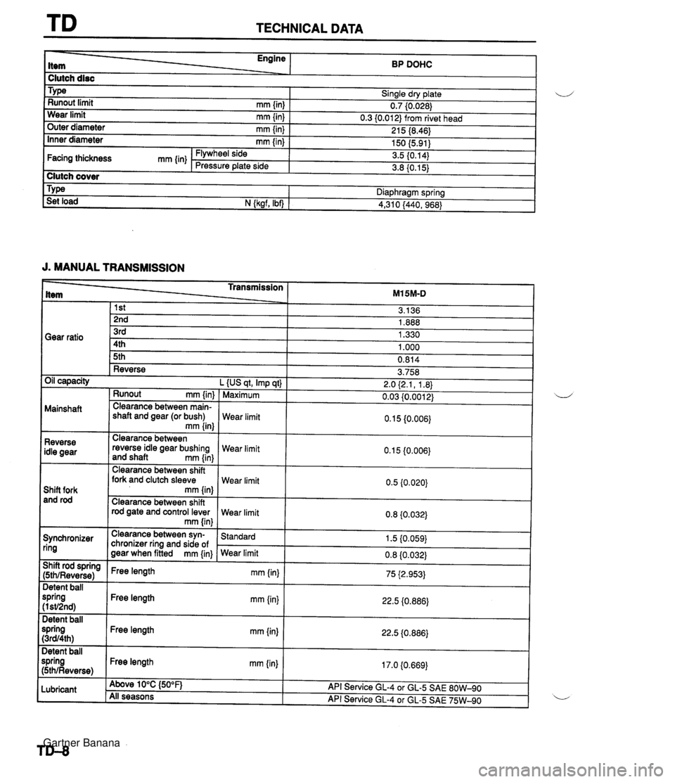
TECHNICAL DATA Engine ------ BP DOHC I Clutch disc I Sinale drv date I u - w- ., Runout limit rnrn {in) 0.7 (0.026) Wear limit rnm linl 0.3 10.01 2) from rivet head . a, 1 outer diameter mm {in) I 215 (8.46) 1 J. MANUAL TRANSMISSION 150 (5.91) 3.5 (0.14) 3.8 (0.15) Inner diameter mm {in) Type _____L- Transmission ___2_ M15M-D Clutch cover Facing thickness mm {in) Diaphragm spring Flywheel side Pressure plate side Set load N {ksrf. Ibn 1 4,310 /440. 968) Gear ratio Runout rnm {in) Mainshaft Clearance between main- shaft and gear (or bush) mm {in} t-- Reverse Oil capacity L {US qt, Imp qt) 1 Maximum 3rd 4th 5th 3.758 2.0 (2.1, 1.8) 0.03 10.001 2) Clearance between shift fork and clutch sleeve Shift fork and rod rod gate and control lever 1.330 1 .OOO 0.814 Reverse idle gear Clearance between reverse idle gear bushing and shaft mrn {in) Synchronizer ring Wear limit Wear limit Clearance between syn- chronizer ring and side of gear when fitted mm {in} Wear limit 0.1 5 {0.006) Wear limit Wear limit I 1 mm {in) ( 75 i2.953) Standard 1.5 (0.059) 22.5 (0.886) 22.5 i0.886) 17.0 (0.669) Detent ball spring (I sV2nd) Detent ball spring (3~94th) Detent ball spring (5thlReverse) Lubricant Free length mm (in) Free length mrn {in) Free length mm {in) Above 10°C {50°F} All seasons API Service GL-4 or GL-5 SAE 80W-90 API Service GL-4 or GL-5 SAE 75W-90 Gartner Banana
Page 1120 of 1708
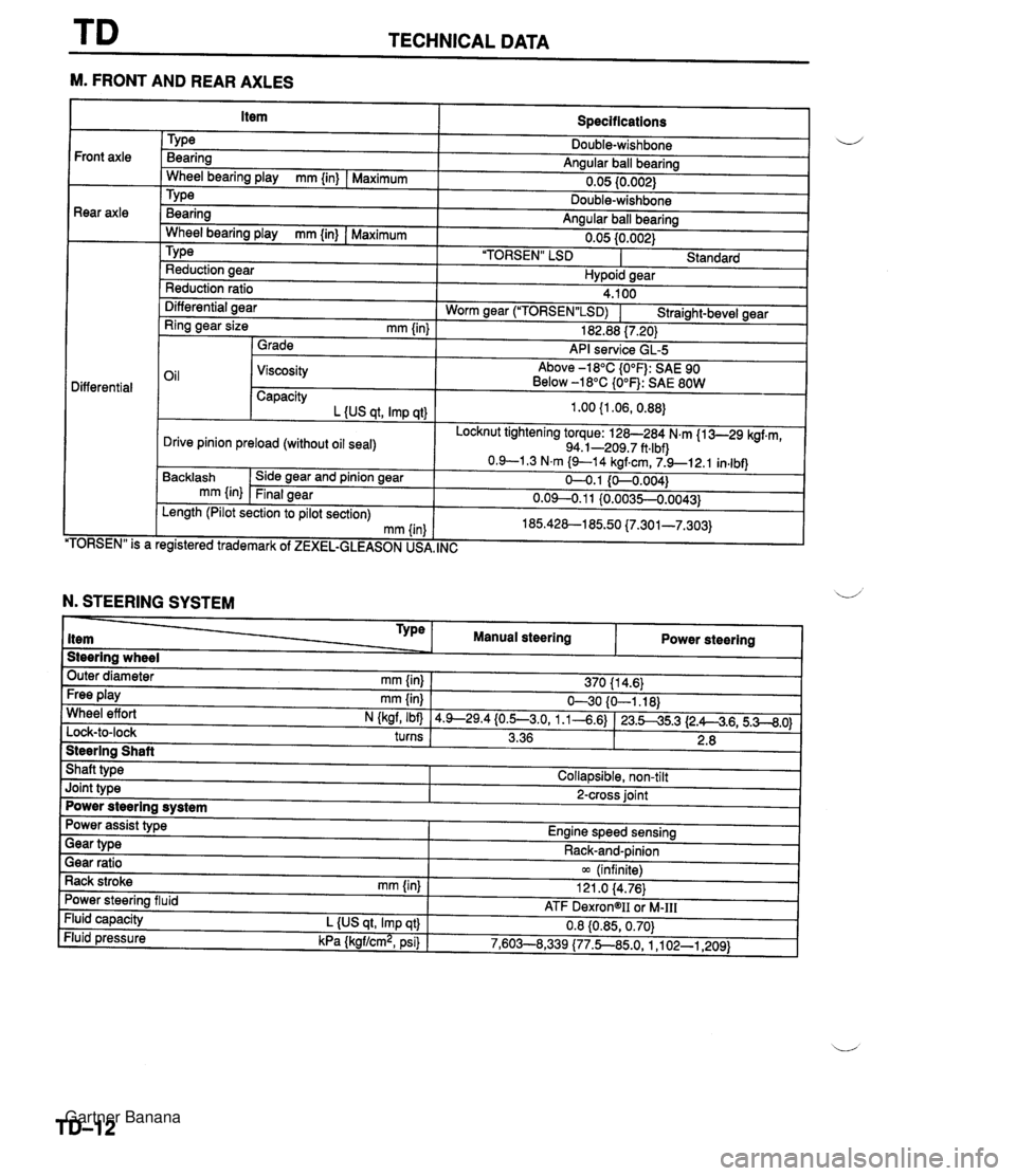
TECHNICAL DATA --- M. FRONT AND REAR AXLES Specifications TY pe Bearing Angular ball bearing 0.05 10.002) Front axle Rear axle - Wheel bearing play mm {in) I Maximum Bearina Anaular ball bearina . .. Wheel bearina plav mm {in) I Maximum " " 0.05 {0.002) 'TORSEN" LSD I Standard TY pe Reduction aear Hvpoid sear Reduction ratio Differential aear 4.100 Worm near ("1ORSEN"LSD) I Straiaht-bevel gear - - Ring gear size mm {in) 1 Grade 182.88 17.201 API service GL-5 Oil 1 Viscosity Above -18°C {O°F): SAE 90 Below -18°C {O°F): SAE 80W Differential Capacity L {US at. Imp at) Locknut tightening torque: 128-284 N.m {I 3-29 kgf.m, 94.1-209.7 ft.lbf) Drive pinion preload (without oil seal) TORSEN" is a Backlash mm {in) . , egistered trademark of ZEXEL-GLEASON US, Side gear and pinion gear Final gear , INC Length (Pilot section to pilot section) mm (in N. STEERING SYSTEM Steering wheel Outer diameter mm {in} 1 370 11 4.6) Type item Free play mm {in) I 630 {O-1.18) Wheel effort N (kaf, Ibfl 14.9--29.4{0.5--3.0, 1.1-4.6) 123.545.3 12.A4.6,5.3--8.0) turns I 3.36 1 2.8 I 1 Manual steering Steering Shaft Shaft type I Collapsible, non-tilt Power steering Joint type I 2-cross joint Power steering system Gear ratio 1 m (infinite) Rack stroke rnm {in) I 121 .O 14.76) Power assist type Engine speed sensing Power steering fluid Fluid capacity L {US qt, Imp qt} Fluid pressure kPa {kgf/cm2, psi) Gear type - - ATF DexrongII oi M-111 0.8 {0.85,0.70) 7,603--8,339 (77.5850, 1 ,I 02-1,209) Rack-and-pinion Gartner Banana
Page 1125 of 1708
SPECIAL TOOLS GENERAL INFORMATION The letters A and B in the priority column indicate the degree of importance of each tool. A . . . . . Indispensable u The tools ranked A in this list are indispensable for performing operations satisfactorily, easily, safely, and efficiently. It is, therefore, advisable that all service shops have these tools. B . . . . . Selective The tools ranked B are not as necessary as tools ranked A, but all service shops should have them to perform repairs more easily and efficiently. 25USTX-001 Gartner Banana