1994 MAZDA MX-5 brake light
[x] Cancel search: brake lightPage 9 of 1708

ABBREVIATIONS 4BDC .... 4BS ...... 4CC ...... 4T ........ 4TDC ..... 4TF ...... 4TS ...... 3AC ...... 3BDC .... 3TDC ..... :ID ....... 2U ....... IOHC .... IRL ...... ITM ...... IC-AT .... iGRA .... EGRV .... ELR ...... EPC ...... ESPS ..... ETS ...... EX ....... FMEM .... HFC ...... HLA ...... H U ....... IC ........ IG ........ IN ........ INT ....... LFC ...... LH ....... LSD ...... M ........ MAF RTN . MT ....... PCTS ..... PCV ...... PIP ....... PRC ...... PIS ....... PMI ...... PWR GND RH ....... RPM ...... RTS ...... SIG RTN . . SLS ...... ... SPOUT S R ....... SST ...... ST ....... SW ....... TDC ...... TNS ...... TRS ...... VPWR .... WSS ..... WTS...... After bottom dead center Antilock brake system Accessory Automatic transmission After top dead center Automatic transmission fluid Ambient temperature sensor Bypass air control Before bottom dead center Before top dead center Cylinder identification display Control unit Double overhead camshaft Daytime running light Diagnostic test mode Electronically controlled automatic transmission EGR air solenoid valve EGR vacuum solenoid valve Emergency locking retractor Electronic pressure control Engine speed sensing power steering Evaporator temperature sensor Exhaust Failure mode effects management High fan control Hydraulic lash adjuster Hydraulic unit Integrated circuit Ignition Intake Intermittent Low fan control Left hand Limited slip differential Motor Mass airflow return Manual transmission Passenger compartment temperature sensor Positive crankcase ventilation Profile ignition pickup Pressure regulator control Power steering Power window Power ground Right hand Revolutions per minute Reduce torque signal Signal return Slip lockup signal Spark output Sensor rotor Special service tool Start Switch Top dead center Tail number side (taillights, license plate lights and side marker lights) Torque reduced signal Vehicle power Wheel speed sensor Water temperature sensor Gartner Banana
Page 23 of 1708

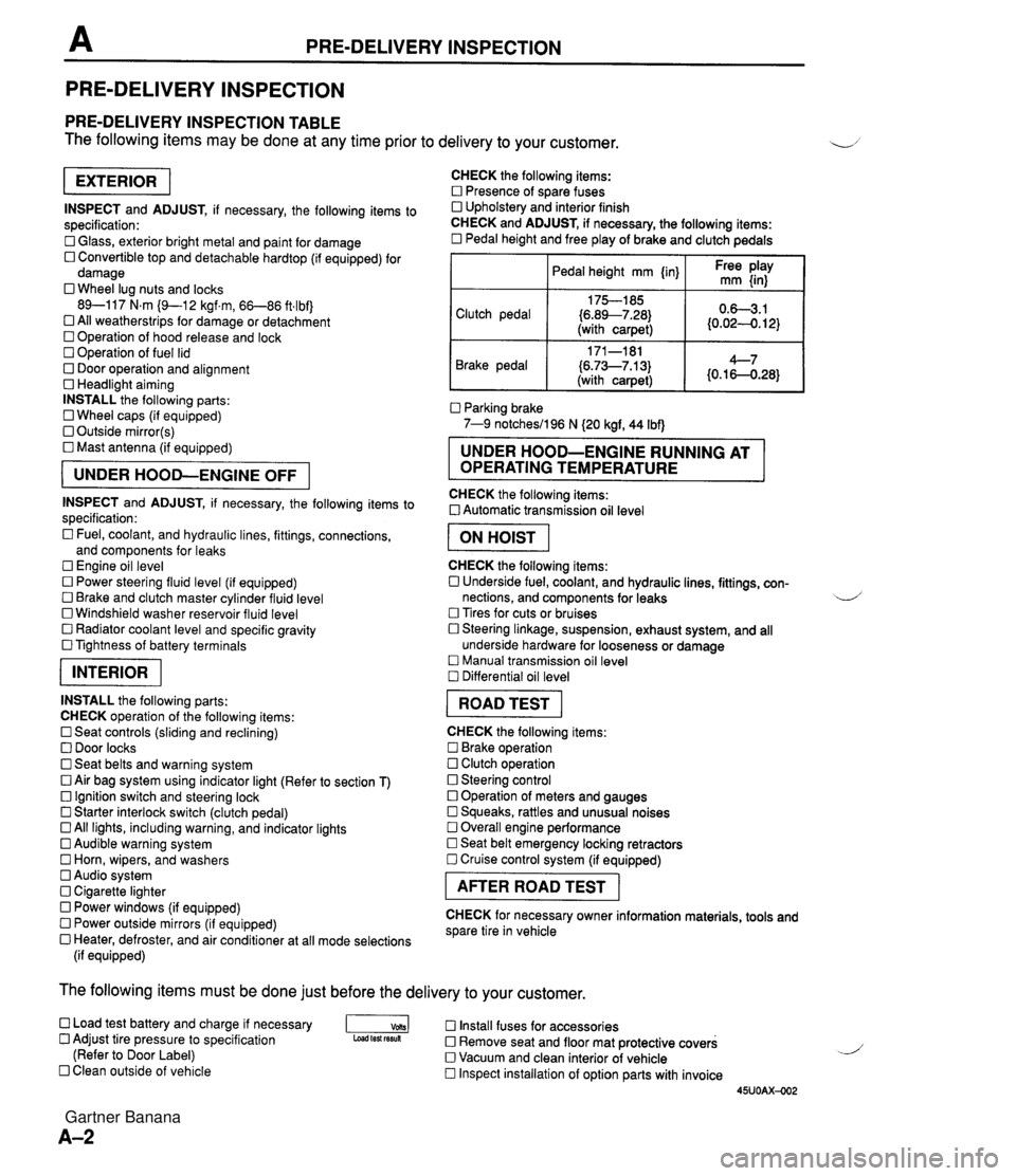
PRE-DELIVERY INSPECTION PRE-DELIVERY INSPECTION PRE-DELIVERY INSPECTION TABLE The following items may be done at any time prior to delivery to your customer. INSPECT and ADJUST, if necessary, the following items to specification: 0 Glass, exterior bright metal and paint for damage 0 Convertible top and detachable hardtop (if equipped) for damage 0 Wheel lug nuts and locks 89-117 N.m (9-1 2 kgf.m, 66-86 ft4bf) 0 All weatherstrips for damage or detachment Operation of hood release and lock Operation of fuel lid 0 Door operation and alignment Headlight aiming INSTALL the following parts: Wheel caps (if equipped) 0 Outside mirror(s) 0 Mast antenna (if equipped) UNDER HOOD-ENGINE OFF INSPECT and ADJUST, if necessary, the following items to specification : Fuel, coolant, and hydraulic lines, fittings, connections, and components for leaks Engine oil level 0 Power steering fluid level (if equipped) Brake and clutch master cylinder fluid level 0 Windshield washer reservoir fluid level 0 Radiator coolant level and specific gravity 0 Tightness of battery terminals pKiq INSTALL the following parts: CHECK operation of the following items: 0 Seat controls (sliding and reclining) 0 Door locks 0 Seat belts and warning system 0 Air bag system using indicator light (Refer to section T) Ignition switch and steering lock 0 Starter interlock switch (clutch pedal) All lights, including warning, and indicator lights 0 Audible warning system 0 Horn, wipers, and washers Audio system 0 Cigarette lighter Power windows (if equipped) 0 Power outside mirrors (if equipped) 0 Heater, defroster, and air conditioner at all mode selections (if equipped) CHECK the following items: Presence of spare fuses 0 Upholstery and interior finish CHECK and ADJUST, if necessary, the following items: 0 Pedal height and free play of brake and clutch pedals I Pedal height mm {in} I Ft: $iy I Clutch pedal {6.89--7.28) (with carpet) Parking brake 7-9 notchesil96 N (20 kgf, 44 Ibf) 0.63.1 (0.024. 12) Brake pedal RUNNING AT OPERATING TEMPERATURE CHECK the following items: 0 Automatic transmission oil level 171-181 (6.73--7.13) (with carpet) I ON HOIST I 4--7 {0.16-0.28} CHECK the following items: 0 Underside fuel, coolant, and hydraulic lines, fittings, con- nections, and components for leaks 4 Tires for cuts or bruises 0 Steering linkage, suspension, exhaust system, and all underside hardware for looseness or damage Manual transmission oil level Differential oil level I ROAD TEST I CHECK the following items: Brake operation Clutch operation 0 Steering control 0 Operation of meters and gauges Squeaks, rattles and unusual noises 0 Overall engine performance Seat belt emergency locking retractors 0 Cruise control system (if equipped) I AFTER ROAD TEST I CHECK for necessary owner information materials, tools and spare tire in vehicle The following items must be done just before the delivery to your customer. 0 Load test battery and charge if necessary -1 Install fuses for accessories Adjust tire pressure to specification Load test fesuk 0 Remove seat and floor mat protective covers (Refer to Door Label) 0 Vacuum and clean interior of vehicle Clean outside of vehicle Inspect installation of option parts with invoice 45UOAX-002 Gartner Banana
Page 246 of 1708

ON-BOARD DIAGNOSIS SYSTEM Stoplight switch OK Release brake pedal Stoplight switch (MT) Headlight switch PC: Stoplight switch malfunction (Refer to Section T) 0 Open circuit in wire harness from stoplight switch to powertrain control module (engine) Powertrain control module (engine) terminal 10 malfunction (Refer to page F-145) Headlight switch OK Turn OFF headlight switch I I NO ---c L, Blower switch YES Depress brake pedal and verify that monitor lamp illuminates PC: Headlight switch malfunction (Refer to section T) Open circuit in wire harness from headlight switch to powertrain control module (engine) Powertrain control module (engine) terminal 1 U malfunction (Refer to page F-146) Turn ON headlight switch Verify that monitor lamp illuminates Verify that monitor lamp illuminates NO - I YES YES Blower switch OK Turn OFF blower switch Air conditioning sensor PC: Blower switch malfunction (Refer to section T) 0 Open circuit in wire harness from blower switch to powertrain control module (engine) 0 Powertrain control module (engine) terminal IS malfunction (Refer to page F-146) 1 I YES I ' Set fan speed control to low position Turn air conditioning sensor ON, and verify that monitor lamp illuminates PC: Air conditioning sensor malfunction (Refer to Section U) Blower switch malfunction Open circuit in wire harness from air conditioning sensor to blower switch Powertrain control module (engine) terminal 1Q malfunction (Refer to page F-146) NO' 4 Air conditioning sensor OK Turn air conditioning sensor and blower switch OFF Rear window defroster switch Turn rear window defroster switch ON Is monitor lamp illuminated? NO PC: Rear window defroster switch malfunction (Refer to Section T) Open circuit in wire harness (Rear window defroster switch - PCME) PCME terminal 2L voltage incorrect (Refer to page F-146) PCME malfunction YES Turn rear window defroster switch OFF u Rear window defroster switch OK Gartner Banana
Page 294 of 1708

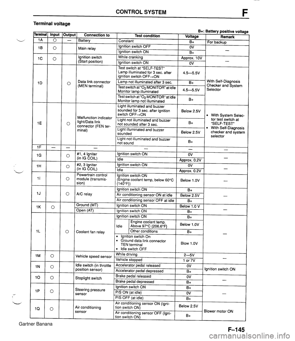
CONTROL SYSTEM F Terminal voltage B+: Battery positive voltage Test condition I Voltage I Remark - - - - - - - - - - - - - - - - - - Connection to Battery Constant Ignition switch OFF Main relay - B+ OV lgnition switch (Start position) For backup - Ignition switch ON While cranking Lamp illuminated for 3 sec. after 1 4.5-5.5V ianition switch OFF+ON 1 B+ Approx. 1 OV Ignition switch ON - - OV Data link connector (MEN terminal) Test switch at "SELF-TEST" .. Lamp not illuminated after 3 sec. Test switch at "02 MONITOR" at idle Monitor lam illuminated & 4.5-5.5v . . I Malfunction indicator IighVData link connector (FEN ter- minal) With Self-Diagnosis Checker and System Selector Test switch at "02 MONITOR" at idle Monitor lamp not illuminated Light illuminated and buzzer sounded for 3 sec. after ignition switch OFF-ON B+ tor tesiswitch at "SELF-TEST" With Self-Diagnosis checker and system selector Below 2.5V 1 Light illuminated and buzzer sounded 1 Below 2.5V I With System Selec- Light not illuminated and buzzer not sounded after 3 sec. I Light not illuminated and buzzer 1 n. 1 B+ not sound I D+ 1 - #I, 4 lgniter (in IG COIL) #2,3 Igniter (in IG COIL) Powertrain control module (transmis- sion) - Ignition switch ON Idle Ignition switch ON Idle lgnition switch ON (Engine coolant temp, below 60°C {I 40°F)) Ignition switch ON AtC relay Air conditioning sensor ON at idle Air conditioning sensor OFF at idle Ground (MT) - OV Approx. 0.2V OV Approx. 0.2V Below 1 .OV B+ Below 2.5V B+ - - - - , * Open (AT) - Ignition switch ON ( Below 1 .O V I Engine coolant temp. I Below .OV I ldle Above 97°C (206.6OF1 Ignition switch ON I I B+ Ignition switch ON Coolant fan relay B+ . - Other conditions lgnition switch On dround data link connector TEN terminal I Blow 1.0" I B+ Vehicle speed sensor ldle switch OFF While driving Vehicle sto~wed ldle switch (in throttle position sensor) 2-5V 1 or 7V . , Accelerator pedal released Accelerator ~edal de~ressed - Stoplight switch OV B+ Brake pedal released Brake ~edal deoressed lgnition switch ON Steering pressure sensor OV B+ I I - Ignition switch ON B+ - PIS ON (at idle) PIS OFF (at idle) Air conditioning sensor Air conditioning sensor ON (Igni- tion switch ON) Air conditioning sensor OFF (Igni- tion switch ON) OV B+ - Below 2.5V B+ Blower motor ON Gartner Banana
Page 414 of 1708

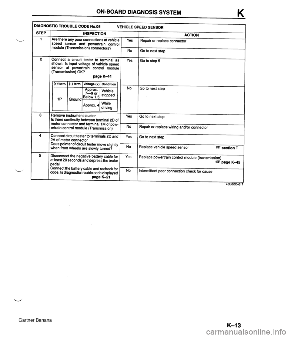
ON-BOARD DIAGNOSIS SYSTEM K )IAGNOSTIC TROUBLE CODE N0.06 VEHICLE SPEED SENSOR INSPECTION STEP ACTION Repair or replace connector Are there any poor connections at vehicle speed sensor and powertrain control module (Transmission) connectors? Yes Go to next step Connect a circuit tester to terminal as shown. Is input voltage of vehicle speed sensor at powertrain control module (Transmission) OK? page K-44 Yes Go to step 5 1 (+) term. I (-) term. ( Voltage (v)( Condition I Go to next step Below 1.5 While Remove instrument cluster Is there continuity between terminal 2D of meter connector and terminal 1 M of pow- ertrain control module (Transmission) Yes Go to next step Repair or replace wiring and/or connector Connect circuit tester to terminals 2D and 2A of meter connector Does pointer of circuit tester move slightly when front wheels are slowly turned? Yes Go to next step Replace vehicle speed sensor section T Disconnect the negative battery cable for at least 20 seconds and depress the brake pedal Connect the battery cable and recheck for code. Is diagnostic trouble code displayed Dane K-21 Yes Replace powertrain control module (transmission) page K-45 Intermittent poor connection check for cause Gartner Banana
Page 451 of 1708

TRANSMISSION TRANSMISSION UNIT (DISASSEMBLY) Preparation SST 49 H075 4958 Body (Part of 49 U019 OAOA) For disassembly of transmission For disassembly of transmission For disassembly of transmission 49 U019 OAOA Hanger set, transmission 49 U019 003 Holder (Part of 49 U019 OAOA) For disassembly of transmission For disassembly of transmission Precaution General notes: 1. The oil pan could contain small chips, shavings, and other particles helpful in checking the condition of the transmission and diagnosing certain problems. To ensure that all foreign particles stay in the oil pan, make sure that the transmission is never tipped completely over while the oil pan is still installed. L/ 2. Disassemble transmission in a clean area (dust proof work space) to prevent entry of dust into the mech- anisms. 3. Inspect the individual transmission components in accordance with the QUICK DIAGNOSIS CHART during disassembly. 4. Use only plastic hammers when applying force to separate the light alloy case joints. 5. Never use rags during disassembly; they may leave particles that can clog fluid passages. 6. Several parts resemble one another; organize them so they do not get mixed up. 7. Disassemble the control valve assembly and thoroughly clean it when a clutch or brake band is burned; or when the ATF has degenerated. Cleaning notes: 1. Clean the transmission exterior thoroughly with steam or cleaning solvents, or both, before disassembly. Warning Using compressed air can cause dirt and other particles to fly out, causing injury to the eyes. Wear protective eye wear whenever using compressed air. 2. Clean the removed parts with cleaning solvent, and dry with compressed air. Clean out all holes and passages with compressed air, and check that there are no obstructions. Gartner Banana
Page 460 of 1708

TRANSMISSION K 29. Remove the bearing races and bearing. 30. Remove the intermediate shaft. I 45UOKX-116 31. Loosen the 2nd band servo locknut and tighten the pis- ton stem. I 1 45UOKX-117 32. Separate the drum support, accumulator and fourth gear case from the transmission case by tapping it lightly with a plastic hammer. Remove the gasket. u 45UOKX-118 Remove the bearing races and bearing from the drum support, accumulator and fourth gear case. Remove the bearing from the front clutch hole. Loosen the 2nd band servo piston stem and remove the 2nd band strut. Hold the brake band together with a piece of wire as shown in the figure. Remove the band strut. Gartner Banana
Page 540 of 1708

TRANSMISSION K DRUM SUPPORT (2) Measure distances C and D with a straight edge and vernier calipers. (3) Calculate the front clutch end play by using the for- mula below. Formula: T=C-04.1 mm {0.0039 In) T Front clutch end play. C: The distance between the drum support mounting surface (including the drum support gasket) of the transmission case and the bearing surface on the front clutch assembly. D: The distance between the sliding surface of the bearing and the drum support gasket contact sur- face. 0.1 :The compression amount of a new gasket. (4) Adjust the front clutch end play by selecting the prop- er bearing race. Front clutch end play: 0.5--0.8mm (0.020--0.031 in) Bearing race sizes rnm (in) 16. Set the 2nd brake band and strut in position. 17. Tighten the piston stem lightly. 18. Apply petroleum jelly to the bearings and bearing races, and install them as shown. Bearing outer diameter 0: 35.0mm (1.38 in) @: 70.0mm (2.76 in) Bearing race outer diameter 0: 76.0mm (2.99 in) 0: 33.0mm (1.30 in) Gartner Banana