Page 216 of 1708
![MAZDA MX-5 1994 Workshop Manual TROUBLESHOOTING GUIDE TEP 27 INSPECTION KNOCKING ACTION 30 to next step TROUBLESHOOTING HINTS] > AirIFuel mixture too lean @I Incorrect ignition timing (too advance) Fuel injection amount incorrect Q MAZDA MX-5 1994 Workshop Manual TROUBLESHOOTING GUIDE TEP 27 INSPECTION KNOCKING ACTION 30 to next step TROUBLESHOOTING HINTS] > AirIFuel mixture too lean @I Incorrect ignition timing (too advance) Fuel injection amount incorrect Q](/manual-img/28/57072/w960_57072-215.png)
TROUBLESHOOTING GUIDE TEP 27 INSPECTION KNOCKING ACTION 30 to next step TROUBLESHOOTING HINTS] > AirIFuel mixture too lean @I Incorrect ignition timing (too advance) Fuel injection amount incorrect Q Overheating Fuel line pressure decreases while accelerating @I Carbon deposits in engine :heck if "00" is displayed on Self-Diagnosis Check- br with ignition switch ON page F-79 Yes Diagnostic Trouble Code No. displayed Check for cause (Refer to specified check sequence) page F-81 "88" flashes Check PCME terminal 1 E voltage uzf page F-145 Specification: Battery positive voltage (Ignition switch ON) 0 If OK, replace PCME page 6143 s If not OK, check wiring between PCME and Self-Diagno- sis Checker page F-7 >heck switches for correct operation with Self- liagnosis Checker Monitor Lamp and ignition ;witch ON as page F-95 SELECT SW A Yes - No Go to next step Lamp not ONIOFF with specified switch Check for cause (Refer to specified check sequence) page F-96 MONl LAMP II- SYSTEM SELECT 1 Lamp always ON Check wiring between PCME terminal 1 D and Self-Diag- nosis Checker uzf page F-7 Zheck if PCME terminal voltages are OK :1R, IT, 2D, 20, and 2Q) page F-146 Yes Go to next step Check for cause (Refer to "Check Point for Each Termi- nal") uzf page F-148 Sheck for correct intake manifold vacuum at idle Yes - No Go to next step Vacuum: More than 450 mmHg (17.7 InHg) VACUUM GAUGE Check for air leakage of intake air system components as page F-100 Check if air cleaner element is clean page F-76 Yes - No Go to next step Replace air cleaner element page F-99 Gartner Banana
Page 317 of 1708

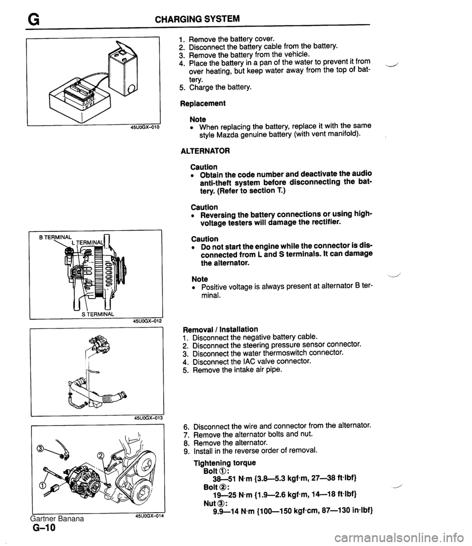
CHARGING SYSTEM B TE S TERMINAL 1. Remove the battery cover. 2. Disconnect the battery cable from the battery. 3. Remove the battery from the vehicle. 4. Place the battery in a pan of the water to prevent it from ,-, over heating, but keep water away from the top of bat- tery. 5. Charge the battery. Replacement Note When replacing the battery, replace it with the same style Mazda genuine battery (with vent manifold). ALTERNATOR Caution Obtain the code number and deactivate the audio anti-theft system before disconnecting the bat- tery. (Refer to section T.) Caution Reversing the battery connections or using high- voltage testers will damage the rectifier. Caution Do not start the engine while the connector is dis- connected from L and S terminals. It can damage the alternator. Note .--,' Positive voltage is always present at alternator B ter- minal. Removal l Installation 1. Disconnect the negative battery cable. 2. Disconnect the steering pressure sensor connector. 3. Disconnect the water thermoswitch connector. 4. Disconnect the IAC valve connector. 5. Remove the intake air pipe. 6. Disconnect the wire and connector from the alternator. 7. Remove the alternator bolts and nut. 8. Remove the alternator. 9. Install in the reverse order of removal. Tightening torque Bolt 0: 38-51 N.m (3.8-5.3 kgf-m, 27-38 ftelbf) Bolt @ : 19-25 N.m j1.9-2.6 kgfem, 14--18 ft-lbf) Nut @I: 9.9--14 N.m (100-150 kgf-cm, 87-1 30 in-lbf) Gartner Banana
Page 1256 of 1708

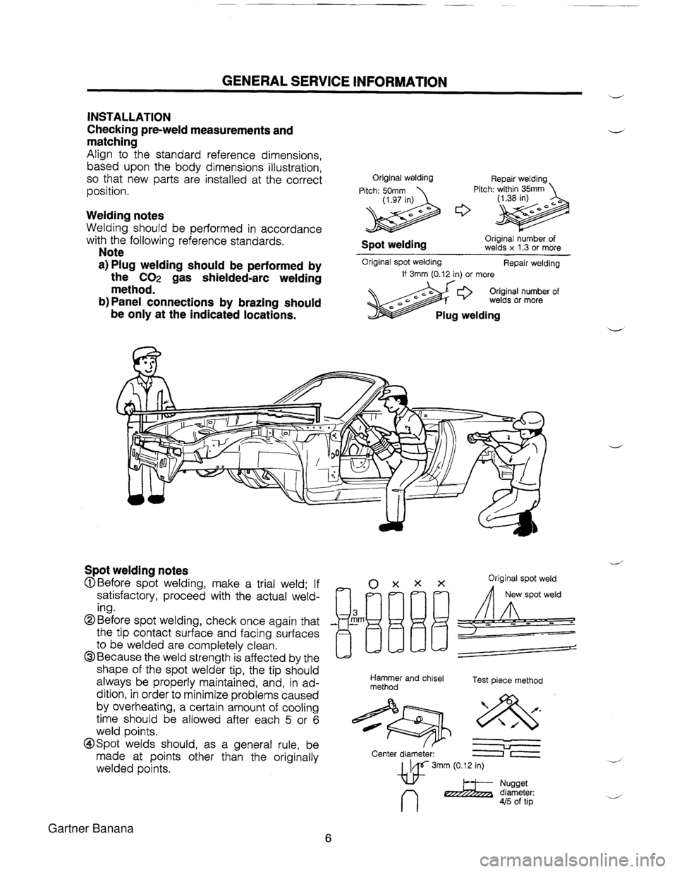
GENERAL SERVICE INFORMATION d INSTALLATION Checking pre-weld measurements and matching Align to the standard reference dimensions, based upon the body dimensions illustration, so that new parts are installed at the correct position. Welding notes Welding should be performed in accordance with the following reference standards. Note a) Plug welding should be performed by the CO2 gas shielded-arc welding method. b) Panel connections by brazing should be only at the indicated locations. Original welding Repair welding Pitch: 50mm Pitch: within 35mm (1.97 in) Original number of Spot welding welds x 1.3 or more Original spot welding Repair welding If 3rnm (0.12 in) or more Original number of welds or more Plug welding Spot welding notes OXXX Original spot weld @Before spot welding, make a trial weld; If satisfactory, proceed with the actual weld- ing. the tip contact surface and facing surfaces ~~[l/jLJL!= @Before spot welding, check once again that - Em -- to be welded are completely clean. @Because the weld strength is affected by the / shape of the spot welder tip, the tip should always be properly maintained, and, in ad- Hammer and chisel Test piece method method dition, in order to minimize problems caused by overheating, a certain amount of cooling time should be allowed after each 5 or 6 weld points. @Spot welds should, as a general rule, be & U made at points other than the originally Center diameter: lr welded points. w 3mm (0.12 in) n 2 Yi'%%Lr: 415 of tip Gartner Banana
Page 1332 of 1708

ALUMINUM BODY PARTS Although repair of aluminum components is done by the same procedures as repair of steel com- ponents, certain points should be noted, as described below. 1. Because aluminum has a greater characteristic of expansion/elongation than steel, a lesser strik- ing force should be used for hammering so that the aluminum component does not become excessively distorted. 2. When heat is used as a method of repair of an aluminum component, the temperature should be kept as low as possible, and the heated area restricted as much as possible. This is to prevent a loss of rigidity due to overheating. 3. When removing old paint from aluminum, a fine-grain sandpaper (#I20 - #180) should be used, because aluminum is a relatively soft material. 4. A special aluminum primer must be used before attempting application of putty or paint, be- cause such materials do not adhere well to aluminum. 5. Determine the type of putty to be used (sheet-metal putty or polyethylene putty) according to the condition of the damage. 6. If bare aluminum is exposed as a result of grinding, sanding, etc., apply special primer for aluminum. 7. Such steps as primer surfacer drying, primer surfacer sanding, top-coat application and drying are done in the same way as for steel painting. - Gartner Banana
Page 1342 of 1708
PLASTIC BODY PARTS - 8. Sand the paint around the damaged area with #240 sandpaper to make it smooth. Degrease with appropriate A - A' degreasing agent I3 - 6' Section ,/ ,.. -. Caution Do not use thinners or other chemicals as damage to the surface will result. 9. Spray primer (heat drying) or primer surfacer (air drying) only on the effected area of the part. (Spot spraying) A - A' I3 - 6' Section C - C' D - D' Section 10. Dry the part. 1) Primer (Forced drying) Uniformly heat the repaired part. Heating condition: 80°C (176OF) (The temperature of the part) x 20 minutes Gartner Banana