1994 MAZDA MX-5 fuel tank removal
[x] Cancel search: fuel tank removalPage 153 of 1708

INDEX 1. Fuel tank 4. Two-way check valve .................. Removal / Inspection / Inspection page F-132 Installation ................ page F-111 5. Three-way check valve .................. 2. Fuel filter Inspection page F-132 Replacement ............... page F-113 6. Fuel vapor valve .................. 3. Fuel pump Inspection page F-133 .................. Inspection page F-114 ............... Replacement page F-115 1. Three-way catalyst 2. Exhaust components d Inspection / Replacement .... page F-134 Removal / Inspection / Installation ............... page F-128 Gartner Banana
Page 256 of 1708

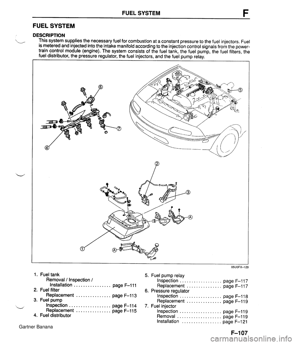
FUEL SYSTEM F FUEL SYSTEM DESCRIPTION . This system supplies the necessary fuel for combustion at a constant pressure to the fuel injectors. Fuel is metered and injected into the intake manifold according to the injection control signals from the power- train control module (engine). The system consists of the fuel tank, the fuel pump, the fuel filters, the fuel distributor, the pressure regulator, the fuel injectors, and the fuel pump relay. I I 1. Fuel tank 5. Fuel pump relay Removal / Inspection / Inspection .................. page F-117 Installation ................ page F-111 Replacement ............... page F-117 2. Fuel filter 6. Pressure regulator Replacement ............... page F-113 Inspection .................. page F-118 3. Fuel pump Replacement ............... page F-119 .................. w Inspection page F-114 7. Fuel injector Replacement ............... page F-115 Inspection .................. page F-119 4. Fuel distributor Removal ................... page F-119 Installation ................. page F-121 Gartner Banana
Page 260 of 1708

FUEL SYSTEM FUEL TANK Removal 1 Inspection / Installation b Warning Fuel vapor is hazardous. It can very easily ignite, causing serious injury and damage. Always keep sparks and flames away from fuel. Warning Fuel line spills and leaks are dangerous. Fuel can ignite and cause serious injuries or death and damage. Fuel can also irritate skin and eyes. To prevent this, always complete the "Fuel Line Safety Procedures" on page F-108. Warning Repairing a fuel tank that has not been properly steam cleaned can be dangerous. Explosion or fire may cause death or serious injury. Always properly steam clean a fuel tank before re- pairing it. 1. Disconnect the negative battery terminal. 2. Drain the fuel from the fuel tank. 3. Remove the main silencer. (Refer to page F-128.) 4. Remove the power plant frame. (Refer to section J.) 5. Remove in the order shown in the figure, referring to Removal note. 6. Install in the reverse order of removal, referring to Installation note. Gartner Banana
Page 261 of 1708

FUEL SYSTEM 1. Fuel filler hoses 7. Rear crossmem ber assembly 2. Fuel hoses Removal Note ............. page F-112 3. Evaporative hoses 8. Fuel tank unit 4. Fuel filter bolts 9. Two-way check valve ~4 Removal Note ............. page F-112 10. Fuel vapor valve 5. Brake pipe joint 11. Fuel pump Removal Note ............. page F-112 6. Battery cable Removal Note ............. page F-112 Removal note Fuel filter bolts 1. Remove the fuel filter cover. 2. Remove the fuel filter bolts. (MT) 3. Remove the fuel filter nuts. (AT) 4. Remove the fuel filter with the fuel hoses still connected. Brake pipe joint 1. Remove the brake pipe joint nuts. 2. Remove the brake pipe joint with the brake pipe and brake hose still connected. Battery cable Remove the battery cable clamp as shown in the figure. Rear crossmember assembly 1. Support the rear crossmember assembly with a trans- mission jack. 2. Remove the rear crossmember mounting bolts and nuts. 3. Lower the rear crossmember assembly. Gartner Banana
Page 262 of 1708

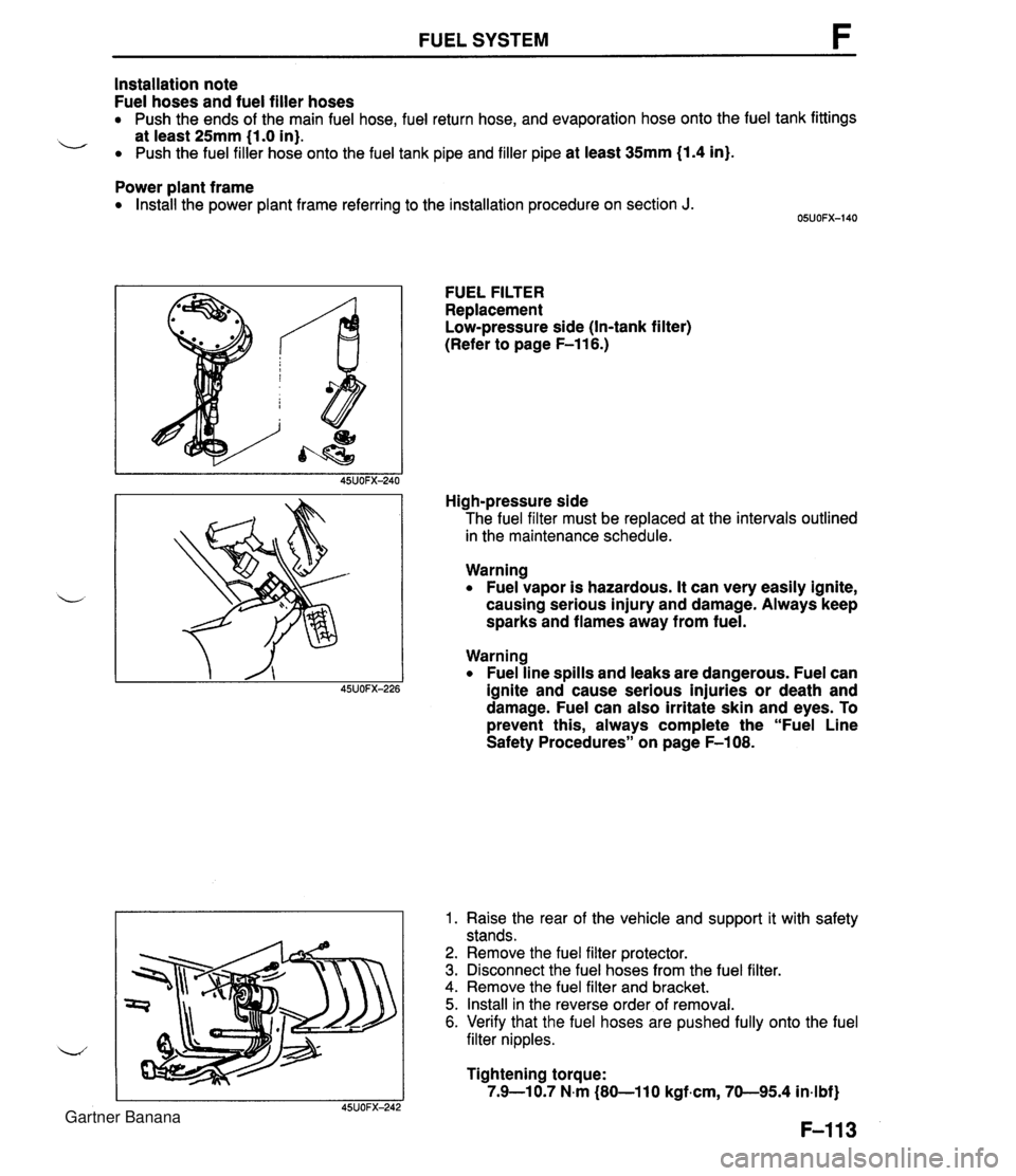
FUEL SYSTEM Installation note Fuel hoses and fuel filler hoses Push the ends of the main fuel hose, fuel return hose, and evaporation hose onto the fuel tank fittings L at least 25mm (1.0 in). Push the fuel filler hose onto the fuel tank pipe and filler pipe at least 35117171 (1.4 in). Power plant frame Install the power plant frame referring to the installation procedure on section J. FUEL FILTER Replacement Low-pressure side (In-tank filter) (Refer to page F-116.) High-pressure side The fuel filter must be replaced at the intervals outlined in the maintenance schedule. Warning Fuel vapor is hazardous. It can very easily ignite, causing serious injury and damage. Always keep sparks and flames away from fuel. Warning Fuel line spills and leaks are dangerous. Fuel can ~SJOFX-226 ignite and cause serious injuries or death and damage. Fuel can also irritate skin and eyes. To prevent this, always complete the "Fuel Line Safety Procedures" on page F-108. 1. Raise the rear of the vehicle and support it with safety stands. 2. Remove the fuel filter protector. 3. Disconnect the fuel hoses from the fuel filter. 4. Remove the fuel filter and bracket. 5. Install in the reverse order of removal. 6. Verify that the fuel hoses are pushed fully onto the fuel filter nipples. Tightening torque: 7.9-10.7 N.m (80-110 kgfam, 70-95.4 in-lbf) Gartner Banana
Page 265 of 1708

FUEL SYSTEM -- FUEL TANK GAUGE SENDER UNIT SIDE FUEL PUMP 45UOFX-256 1. Remove the rear package trim. 2. Remove the service hole cover. 3. Remove the fuel pump cover. 4. Disconnect the fuel pump connector. 5. Disconnect the fuel hoses. 6. Remove the fuel pump and fuel tank gauge sender unit assembly. 7. Remove the fuel pump. 8. Install in the reverse order of removal, referring to Instal- lation note. Installation note O-ring set 1. Use a new O-ring set. (O-ring, cap, and spacer) 2. Apply oil or fuel to the O-ring set before installing. 3. To confirm sealing of the O-ring, after assembling the fuel pump and fuel tank gauge sender unit, blow air through the fuel main pipe and verify that no air flows. If air flows the check ball may be stuck. Shake the fuel pump 2 or 3 times and recheck. Fuel pump After installing the fuel pump to the bracket, pull down the fuel pump down so that it is tight against the bracket. Gartner Banana
Page 846 of 1708

BODY ELECTRICAL SYSTEM ................................... INDEX T- 2 ........................... SWITCHES T- 2 FUSES AND RELAYS .................. T- 3 .............................. LIGHTS T- 4 CRUISE CONTROL SYSTEM ........... T- 5 ...................... AUDIO SYSTEM T- 6 SRS AIR BAG SYSTEM ................ T- 7 ............................... OUTLINE T- 8 TROUBLESHOOTING GUIDE ........... T- 8 ELECTRICAL SYMBOLS ............... T- 9 ................................... FUSE T- 10 STRUCTURAL VIEW ................... T- 10 ...................... SPECIFICATIONS T- 11 ........................ DESCRIPTION T- 12 ....................... REPLACEMENT T- 12 ....................... RELAY .. ....... T- 13 STRUCTURAL VIEW ................... T- 13 ........................ DESCRIPTION T- 13 RETRACTABLE HEADLIGHT RELAY .... T- 14 ....................... FLASHER UNIT T- 14 ........................... TNS RELAY T- 15 .......................... HORN RELAY T- 15 COOLANT FAN RELAY ................. T- 15 REAR WINDOW DEFROSTER RELAY ... T- 16 HEADLIGHT RELAY ................... T- 16 ................................ SWITCH T- 17 ................... STRUCTURAL VIEW T- 17 ........................ DESCRIPTION T- 17 .................... IGNITION SWITCH T- 18 COMBINATION SWITCH ............... T- 19 RETRACTOR SWITCH AND HAZARD WARNING ............................. SWITCH T- 21 ................. INSTRUMENT CLUSTER T- 22 ................... STRUCTURAL VIEW T- 22 ........................ DESCRIPTION T- 22 .................... CIRCUIT DIAGRAM T- 23 ................. TROUBLESHOOTING T- 24 ............ REMOVAL / INSTALLATION T- 29 ........... DISASSEMBLY 1 ASSEMBLY T- 29 ...................... SPEEDOMETER T- 30 ........................ TACHOMETER T- 30 WATER TEMPERATURE GAUGE ....... T- 30 ......................... FUEL GAUGE T- 31 OIL PRESSURE GAUGE ............... T- 31 .................... PRINTED CIRCUIT T- 32 VEHICLE SPEED SENSOR ............. T- 32 WATER TEMPERATURE SENDER UNlT . T- 32 FUEL GAUGE SENDER UNlT ...................... (IN FUEL TANK) T- 32 OIL PRESSURE SENSOR .............. T- 33 ............... SPEEDOMETER CABLE T- 33 WARNING LIGHT AND SENDER UNIT ..... T- 34 ................... STRUCTURAL VIEW T- 34 CIRCUIT DIAGRAM .................... T- 35 ................. TROUBLESHOOTING T- 36 BRAKE FLUID LEVEL SENSOR ......... T- 39 PARKING BRAKE SWITCH ............. T- 39 ..................... BUCKLE SWITCH T- 39 ...................... LIGHTING SYSTEM T- 40 ................... STRUCTURAL VIEW T- 40 ......................... HEADLIGHTS T- 41 ......................... STOPLIGHTS T- 53 TURN AND HAZARD WARNING LIGHTS . T- 57 ..................... BACK-UP LIGHTS T- 66 TAILLIGHTS. SIDE MARKER LIGHTS. PARKING LIGHTS AND LICENSE PLATE LIGHTS . T- 69 DAYTIME RUNNING LIGHTS (DRL) .................... (CANADA SPEC.) T- 72 ........... REAR COMBINATION LIGHT T- 76 .................... INTERIOR LIGHTS T- 78 ................ ILLUMINATION LIGHTS T- 82 .................................. HORN T- 84 ................... STRUCTURAL VIEW T- 84 .................... CIRCUIT DIAGRAM T- 85 ................. TROUBLESHOOTING T- 86 ............ REMOVAL 1 INSTALLATION T- 87 ............ REAR WINDOW DEFROSTER T- 89 ................... STRUCTURAL VIEW T- 89 ........................ DESCRIPTION T- 89 ................. TROUBLESHOOTING T- 90 ................ REPAIRING FILAMENT T- 93 ............. CRUISE CONTROL SYSTEM T- 94 ................... STRUCTURAL VIEW T- 94 .................... CIRCUIT DIAGRAM T- 95 ................. TROUBLESHOOTING T- 96 ....... SELF-DIAGNOSTIC INSPECTION T-100 ............... CRUISE CONTROL UNIT T-103 .................... ACTUATOR CABLE T-104 ..................... CLUTCH SWITCH T-105 .......... STOP LIGHTIBRAKE SWITCH T-105 ...... CRUISE CONTROL MAIN SWITCH T-106 ........... CRUISE CONTROL SWITCH T-106 ............. VEHICLE SPEED SENSOR T-106 ........................... ACTUATOR T-107 a .................................. AUDIO T-108 ................... STRUCTURAL VIEW T-108 ................... SYSTEM DIAGRAM T-109 ............................ FEATURES T-110 FUNCTION AND OPERATING ......................... PROCEDURE 1-111 ............. OPERATION DESCRIPTION T-113 .................. ANTITHEFT SYSTEM T-120 ................. TROUBLESHOOTING T-122 ............ REMOVAL I INSTALLATION T-145 .................... POWER ANTENNA T-149 ......................... INSPECTION T-153 CONNECTOR TERMINAL .................... SPECIFICATIONS T-154 SRS AIR BAG SYSTEM .................. T-156 PREPARATION ........................ T-156 ................... STRUCTURAL VIEW T-156 .......... COMPONENT DESCRIPTION T-157 SYSTEM DIAGRAM ................... T-158 ................. SERVICE WARNINGS T-159 GENERAL PROCEDURES ............. T-160 TROUBLESHOOTING ................. T-160 DRIVER-SIDE AIR BAG MODULE ....... T-206 PASSENGER-SIDE AIR BAG MODULE . . T-207 DIAGNOSTIC MODULE ................ T-208 CLOCK SPRING ....................... T-209 CRASH SENSOR (D-SENSOR) ......... T-210 CRASH SENSOR (S-SENSOR) ......... T-213 AIR BAG MODULE DISPOSAL . .. PROCEDURE ........................ T-215 INSPECTION OF SST (DEPLOYMENT TOOL) ............... T-217 Gartner Banana