1994 JEEP CHEROKEE remote
[x] Cancel search: remotePage 258 of 1784
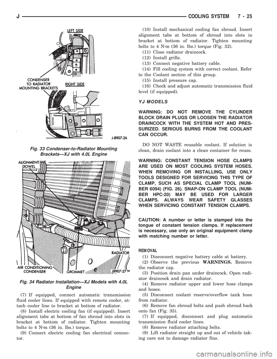
(7) If equipped, connect automatic transmission
fluid cooler lines. If equipped with remote cooler, at-
tach cooler line to bracket at bottom of radiator.
(8) Install electric cooling fan (if equipped). Insert
alignment tabs at bottom of fan shroud into slots in
bracket at bottom of radiator. Tighten mounting
bolts to 4 Nzm (36 in. lbs.) torque.
(9) Connect electric cooling fan electrical connec-
tor.(10) Install mechanical cooling fan shroud. Insert
alignment tabs at bottom of shroud into slots in
bracket at bottom of radiator. Tighten mounting
bolts to 4 Nzm (36 in. lbs.) torque (Fig. 32).
(11) Close radiator draincock.
(12) Install grille.
(13) Connect negative battery cable.
(14) Fill cooling system with correct coolant. Refer
to the Coolant section of this group.
(15) Install pressure cap.
(16) Check and adjust automatic transmission fluid
level (if equipped).
YJ MODELS
WARNING: DO NOT REMOVE THE CYLINDER
BLOCK DRAIN PLUGS OR LOOSEN THE RADIATOR
DRAINCOCK WITH THE SYSTEM HOT AND PRES-
SURIZED. SERIOUS BURNS FROM THE COOLANT
CAN OCCUR.
DO NOT WASTE reusable coolant. If solution is
clean, drain coolant into a clean container for reuse.
WARNING: CONSTANT TENSION HOSE CLAMPS
ARE USED ON MOST COOLING SYSTEM HOSES.
WHEN REMOVING OR INSTALLING, USE ONLY
TOOLS DESIGNED FOR SERVICING THIS TYPE OF
CLAMP, SUCH AS SPECIAL CLAMP TOOL (NUM-
BER 6094) (FIG. 26). SNAP-ON CLAMP TOOL (NUM-
BER HPC-20) MAY BE USED FOR LARGER
CLAMPS. ALWAYS WEAR SAFETY GLASSES
WHEN SERVICING CONSTANT TENSION CLAMPS.
CAUTION: A number or letter is stamped into the
tongue of constant tension clamps. If replacement
is necessary, use only an original equipment clamp
with matching number or letter.
REMOVAL
(1) Disconnect negative battery cable at battery.
(2) Observe the previousWARNINGS.Remove
the radiator cap.
(3) Position drain pan under draincock. Open radi-
ator draincock and drain radiator.
(4) Remove radiator upper and lower hose clamps
and hoses.
(5) Disconnect coolant reserve/overflow tank hose
from radiator.
(6) Remove fan shroud bolts and push shroud back
onto fan (Fig. 35).
(7) If equipped, disconnect and plug automatic
transmission fluid cooler lines.
(8) Remove radiator attaching bolts.
(9) Lift radiator straight up and out of vehicle tak-
ing care not to damage radiator fins.
Fig. 33 Condenser-to-Radiator Mounting
BracketsÐXJ with 4.0L Engine
Fig. 34 Radiator InstallationÐXJ Models with 4.0L
Engine
JCOOLING SYSTEM 7 - 25
Page 306 of 1784

OVERHEAD CONSOLE
CONTENTS
page page
COMPASS REPAIR PROCEDURES.......... 4
CONSOLE REPAIR PROCEDURES........... 6
DESCRIPTION........................... 1DIAGNOSTIC PROCEDURES............... 1
THERMOMETER AND SENSOR SYSTEM REPAIR
PROCEDURES......................... 6
DESCRIPTION
The overhead console includes:
²a compass/temperature display
²reading and courtesy lights for the front and rear
seats
²the receiver for the keyless entry system
²storage compartment for remote garage door
opener
²storage compartment for sunglasses.
COMPASS
The compass will display the direction the vehicle
is pointed, using the eight major compass headings
(Examples: North is ``N'', Northeast is ``NE''). It does
not display the headings in actual degrees. The dis-
play is turned on/off using the TEMP/COMP button
on the left of the display.
The compass is a self calibrating unit that should
not require recalibration. The only calibration that
may prove necessary is to drive the vehicle in 3 com-
plete circles, on level ground, in not less than 48 sec-
onds. This will ``reorient'' the unit to its vehicle. The
unit also will compensate for magnetism the vehicle
may acquire during its life. Care should be used to
avoid putting anything magnetic on the roof of the
vehicle.
The unit can compensate for some magnetic fields
in the body. The use of magnetic attachments like
antenna mounts or repair order ``hats'' placed di-
rectly on the roof can exceed the compensation abil-
ity of the unit. Magnetic bit drivers used on the
fasteners to hold the assembly to the roof header can
also affect operation. If the vehicle roof should be-
come magnetized, then the degaussing and calibra-
tion procedures may be required to restore proper
operation.
If the compass functions but accuracy is suspect, it
may be necessary to perform a variation adjustment.
This procedure allows the unit to accommodate vari-
ations in the earth's magnetic field strength based on
geographic location.
If the compass has blanked out and only CAL
appears, degaussing may be necessary to re-
move residual magnetic fields.
THERMOMETER
The ambient temperature display can be changed
from Fahrenheit to Celsius using the U.S./METRIC
button on the right of the display. The temperature
reported is not an instant reading of conditions but
an average temperature. It may take the unit several
minutes to react to a major change such as driving
out of a heated garage into winter temperatures.
When the ignition switch is turned OFF, the last
displayed temperature reading stays in memory.
When the ignition switch is turned ON again the
thermometer will display the memory temperature
for one minute; then update the display to the actual
temperature within five minutes.
READING AND COURTESY LAMPS
All reading and courtesy lamps in the overhead
console are activated by the door courtesy circuit.
When all four doors and the liftgate are closed the
lamps can be activated by depressing the correspond-
ing lens. When any door or the liftgate is open, the
switches are disabled. They will not turn the lamps
off.
MAP AND COURTESY LAMPS
These lamps offer several unique features. Both the
map and courtesy lamps can be turned on with the
integral ``Soft Touch'' switch. Pushing this switch en-
ergizes an electrical circuit, which in turn directs
power to the light. The map lamps are unaffected by
the door switches, while the courtesy lamps are
turned on with the opening of any door. When any
door is open, the ``Soft Touch'' switches are disabled,
you cannot turn the lights off with these switches.
DIAGNOSTIC PROCEDURES
Follow the appropriate diagnostic flow chart:
²Chart 1 describes the procedures for compass and
display problems.
²Chart 2 describes the procedures for illumination
lamp problems.
²Chart 3 describes the procedures for outside tem-
perature measuring problems.
JOVERHEAD CONSOLE 8C - 1
Page 343 of 1784

IGNITION SWITCH
INDEX
page page
General Information....................... 30
Ignition Switch Installation/Adjustment......... 31Ignition Switch Removal................... 30
Ignition Switch Testing..................... 30
GENERAL INFORMATION
The ignition switch is mounted (under the instru-
ment panel) on the lower section of the steering col-
umn. The headlamp dimmer switch is mounted
beside the ignition switch (Fig. 1). Both of these
switches (ignition and dimmer) share the same
mounting screws.
The switch is connected to the ignition key lock as-
sembly by a remote actuator rod. This remote actua-
tor rod fits into an access hole on the bottom of the
ignition switch (Fig. 2).
IGNITION SWITCH REMOVAL
(1) Disconnect the negative battery cable at the
battery.
(2) XJ models: Remove the lower instrument panel
trim assembly. YJ models: Remove the windshield
wiper intermittent control module and its bracket (if
equipped).
(3) Place the ignition key lock in ACCESSORY po-
sition.
(4) Remove the two headlamp dimmer switch at-
taching nuts. Lift the switch from steering column
while disengaging actuator rod.Before removing dimmer switch, tape the two
remote control actuator rods (ignition switch
and dimmer) to the steering column. This will
prevent accidental disengagement from the up-
per part of the steering column.
(5) Remove the ignition switch-to-steering column
attaching screws.
(6) Disengage the ignition switch from the remote
actuator rod by lifting straight up. Remove switch
from steering column.
(7) Remove wiring from switch as follows:
Two electrical connectors are used to connect all
wiring to the ignition switch. One of the connectors
is installed (interlocked) over the top of the other
connector. Remove wiring from switch by disconnect-
ing the (black) harness connector first and then the
other connector. Remove the switch from the vehicle.
IGNITION SWITCH TESTING
To test the ignition switch circuity and continuity,
proceed as follows. Place the slide bar (on the igni-
tion switch) (Fig. 2) into the detent position to be
tested. An ohmmeter or continuity light may be used
to check switch continuity. Refer to the Ignition
Fig. 1 Ignition Switch/Headlamp Dimmer
SwitchÐTypical
Fig. 2 Ignition Switch/Remote Actuator
RodÐTypical
8D - 30 IGNITION SYSTEMSJ
Page 344 of 1784
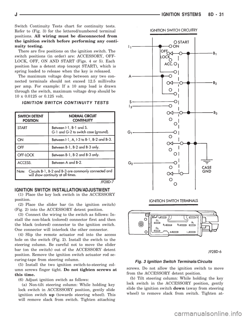
Switch Continuity Tests chart for continuity tests.
Refer to (Fig. 3) for the lettered/numbered terminal
positions.All wiring must be disconnected from
the ignition switch before performing any conti-
nuity testing.
There are five positions on the ignition switch. The
switch positions (in order) are: ACCESSORY, OFF-
LOCK, OFF, ON AND START (Figs. 4 or 5). Each
position has a detent stop (except START), which is
spring loaded to release when the key is released.
The maximum voltage drop between any two con-
nected terminals should not exceed 12.5 millivolts
per amp. For example: If a 10 amp load is drawn
through the switch, maximum voltage drop should be
10 x 0.0125 or 0.125 volt.
IGNITION SWITCH INSTALLATION/ADJUSTMENT
(1) Place the key lock switch in the ACCESSORY
position.
(2) Place the slider bar (in the ignition switch)
(Fig. 2) into the ACCESSORY detent position.
(3) Connect the wiring to the switch as follows: In-
stall the non-black (colored) connector first and then
the black (colored) connector to the ignition switch.
One connector will interlock the other connector.
(4) Slip the remote actuator rod into the access
hole on the switch (Fig. 2). Install the switch to the
steering column. Be careful not to move the slider
bar (on the switch) out of the ACCESSORY detent
position. Remove the ignition switch actuator rod se-
curing-tape from steering column.
(5) Install the two ignition switch-to-steering col-
umn screws finger tight.Do not tighten screws at
this time.
(6) Adjust ignition switch as follows:
(a) Non-tilt steering column: While holding key
lock switch in ACCESSORY position, gently slide
ignition switchup(towards steering wheel). This
will remove slack from switch. Tighten attachingscrews. Do not allow the ignition switch to move
from the ACCESSORY detent position.
(b) Tilt steering column: While holding the key
lock switch in the ACCESSORY position, gently
slide the ignition switchdown(away from steering
wheel) to remove slack from switch. Tighten at-
IGNITION SWITCH CONTINUITY TESTS
Fig. 3 Ignition Switch Terminals/Circuits
JIGNITION SYSTEMS 8D - 31
Page 461 of 1784
ACTUATOR MOTOR STALL TEST
To test the actuator motor, connect an ammeter in
series with the motor and operate the door switch.
Replace the actuator motor if current draw exceeds 8
amps at room temperature or if the actuator does not
complete its travel in less than one second. Refer to
Solenoid and Latch Assembly Replacement procedures.
SWITCH REPLACEMENT
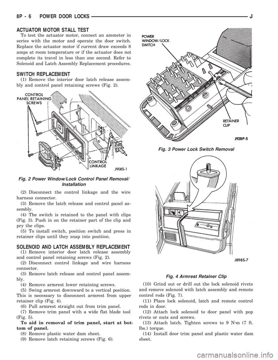
(1) Remove the interior door latch release assem-
bly and control panel retaining screws (Fig. 2).
(2) Disconnect the control linkage and the wire
harness connector.
(3) Remove the latch release and control panel as-
sembly.
(4) The switch is retained to the panel with clips
(Fig. 3). Push in on the retainer part of the clip and
pry the clips.
(5) To install switch, position switch and press in
retainer clips until they snap into position.
SOLENOID AND LATCH ASSEMBLY REPLACEMENT
(1) Remove interior door latch release assembly
and control panel retaining screws (Fig. 2).
(2) Disconnect control linkage and wire harness
connector.
(3) Remove latch release and control panel assem-
bly.
(4) Remove armrest lower retaining screws.
(5) Swing armrest downward to a vertical position.
This is necessary to disconnect armrest from upper
retainer clip (Fig. 4).
(6) Pull armrest straight out from trim panel.
(7) Remove trim panel with a wide flat blade tool
(Fig. 5).
To aid in removal of trim panel, start at bot-
tom of panel.
(8) Remove plastic water dam sheet.
(9) Remove latch retaining screws (Fig. 6).(10) Grind out or drill out the lock solenoid rivets
and remove solenoid with latch assembly and remote
control rods (Fig. 7).
(11) Place lock solenoid, latch and remote control
rods in door.
(12) Attach lock solenoid to door panel with pop
rivets or nuts and screws.
(13) Attach latch. Tighten screws to 9 Nzm(7ft.
lbs.) torque.
(14) Install door trim panel and plastic water dam
sheet.
Fig. 3 Power Lock Switch Removal
Fig. 2 Power Window/Lock Control Panel Removal/
Installation
Fig. 4 Armrest Retainer Clip
8P - 6 POWER DOOR LOCKSJ
Page 642 of 1784
WIRING DIAGRAMS XJ
INDEX
Wiring Diagram Name Sheet Number
A/C Compressor Clutch Relay...................3,69
A/C Compressor Clutch........................69
A/C Heater Blower Motor.......................70
A/C Low Pressure Switch.......................69
A/C Mode Select Switch........................70
A/C Thermostat..............................69
ABS Diode.................................33
ABS Green Indicator Lamp......................57
ABS Hydraulic Actuation Unit.....................33
ABS #1 Relay.............................3,31
ABS #2 Relay.............................3,31
ABS Pump Motor............................30
ABS Red Indicator Lamp.......................57
Ambient Temperature Sensor.....................53
Antenna...................................71
Antenna Mast...............................71
Anti-Lock Brake Control Module Connector...........109
Anti-Lock Braking System...............29,30,31,32,33
ABS Diode...............................33
ABS Relays...............................31
Anti-Lock Pump Motor.......................30
Anti-Lock Brake System Module.........29,30,31,32,33
Data Link Connector.........................32
G Sensor................................30
Hydraulic Actuation Unit......................33
Left Front Wheel Sensor......................29
Left Rear Wheel Sensor.......................29
Pedal Travel Sensor.........................30
Right Front Wheel Sensor.....................29
Right Rear Wheel Sensor......................29
Anti-Lock Brake System Module...........29,30,31,32,33
Anti-Lock Pump Motor.........................30
Anti-Lock Relay..............................31
Ashtray Lamp...............................48
Automatic Shut Down Relay..................3,12,17
Automatic Transmission Control System (2.5L).........27
Front Axle Lock-Up Switch.....................27
EMCC Relay..............................27
EMCC Solenoid............................27
Back-Up Lamp Switch.........................25
Ballast Resistor..............................89
Battery..................................1,7,8
Blower Motor.............................68,70
Blower Resistors...........................68,70
Blower Switch............................68,70
Body Ground...............................44
Brake Warning Switch.........................67
Bulkhead Disconnect.................101,102,103,104
Camshaft Position Sensor.....................11,20
Cargo Lamp................................50
Center High Mounted Stop Lamp..................98
Charging System 2.5L..........................5
Generator.................................5Wiring Diagram Name Sheet Number
Charging System 4.OL..........................6
Generator.................................6
Chime Module..............................74
Ignition Key Warning Switch....................74
Seat Belt Switch...........................74
Cigar Lighter...............................37
Cigar Lighter Lamp...........................48
Circuit Breakers
In Line Circuit Breaker........................2
Trailer Tow In-Line Circuit Breaker................97
Windshield Wiper Circuit Breaker...............63,64
Connectors
Anti-Lock Brake Control Module Connector.........109
Data Link Connector...................16,18,25,32
Instrument Cluster Connector................55,108
Main Body Connectors.......................112
Power Mirror Connector......................110
Powertrain Control Module Connector.............111
Remote Keyless Entry Module Connector...........114
Steering Column Connector...................106
Telltale Connector........................56,107
Trailer Tow Connector........................93
Transmission Control Module Connector...........105
Cooling Fan Relay...........................3,23
Courtesy Lamp..............................49
Crankshaft Position Sensor....................11,20
Data Link Connector....................16,18,25,32
Daytime Running Lamp Module (DRL)...............38
Daytime Running Lamp System...................38
Diode,ABS.................................33
Distributor Ignition Coil.......................16,18
Dome Lamp................................51
Dome And Courtesy Lamps..................49,50,51
Cargo Lamp..............................50
Dome Lamp..............................51
Dome/Reading Lamp.........................51
Glove Box Lamp...........................49
Left Courtesy Lamp.........................49
Reading Lamp.............................51
Right Courtesy Lamp........................49
Vanity Lamps.............................51
Dome Reading Lamp..........................51
Door Jamb Switch System....................75,76
Left Front Door Jamb Switch...................75
Left Rear Door Jamb Switch...................75
Liftgate Switch............................76
Right Front Door Jamb Switch..................76
Right Rear Door Jamb Switch..................76
EMCC Relay...............................3,27
EMCC Solenoid..............................27
Engine Block Coolant Heater/Cigar Lighter............37
Cigar Lighter..............................37
Engine Block Coolant Heater....................37
JWIRING DIAGRAMS 8W - 149
Page 645 of 1784
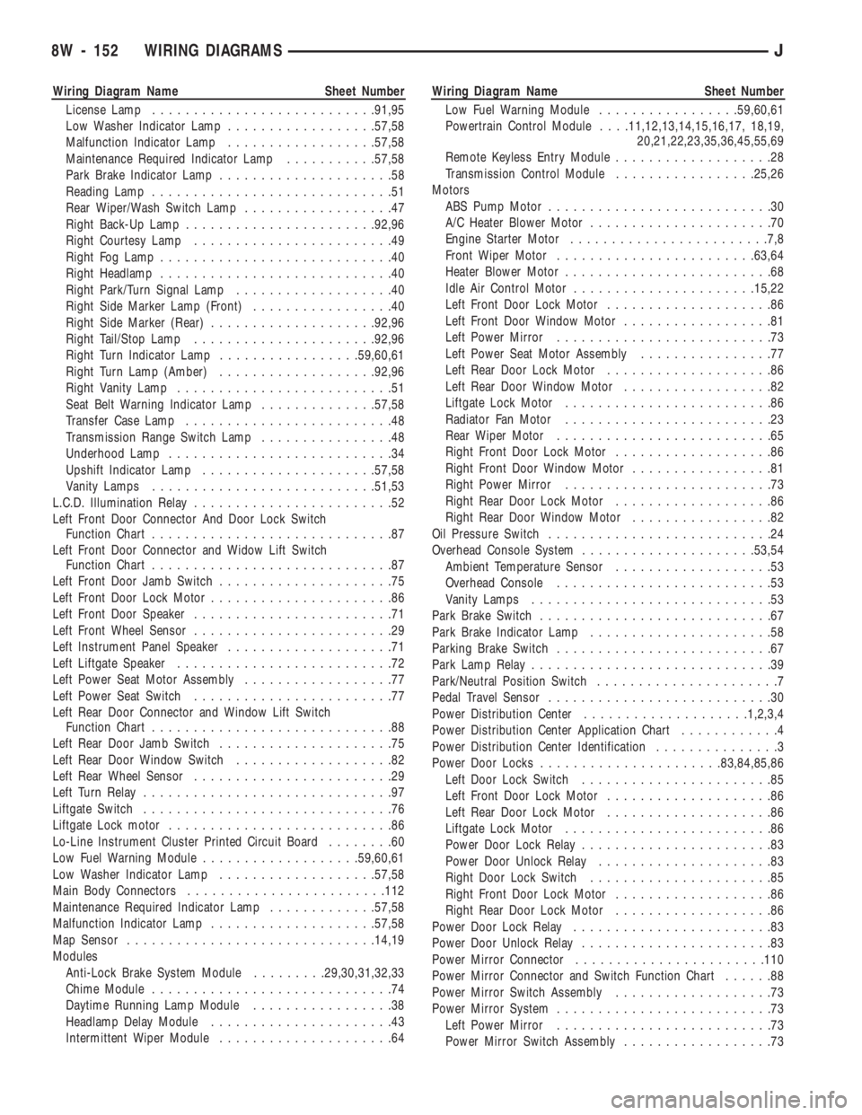
Wiring Diagram Name Sheet Number
License Lamp...........................91,95
Low Washer Indicator Lamp..................57,58
Malfunction Indicator Lamp..................57,58
Maintenance Required Indicator Lamp...........57,58
Park Brake Indicator Lamp.....................58
Reading Lamp.............................51
Rear Wiper/Wash Switch Lamp..................47
Right Back-Up Lamp.......................92,96
Right Courtesy Lamp........................49
Right Fog Lamp............................40
Right Headlamp............................40
Right Park/Turn Signal Lamp...................40
Right Side Marker Lamp (Front).................40
Right Side Marker (Rear)....................92,96
Right Tail/Stop Lamp......................92,96
Right Turn Indicator Lamp.................59,60,61
Right Turn Lamp (Amber)...................92,96
Right Vanity Lamp..........................51
Seat Belt Warning Indicator Lamp..............57,58
Transfer Case Lamp.........................48
Transmission Range Switch Lamp................48
Underhood Lamp...........................34
Upshift Indicator Lamp.....................57,58
Vanity Lamps...........................51,53
L.C.D. Illumination Relay........................52
Left Front Door Connector And Door Lock Switch
Function Chart.............................87
Left Front Door Connector and Widow Lift Switch
Function Chart.............................87
Left Front Door Jamb Switch.....................75
Left Front Door Lock Motor......................86
Left Front Door Speaker........................71
Left Front Wheel Sensor........................29
Left Instrument Panel Speaker....................71
Left Liftgate Speaker..........................72
Left Power Seat Motor Assembly..................77
Left Power Seat Switch........................77
Left Rear Door Connector and Window Lift Switch
Function Chart.............................88
Left Rear Door Jamb Switch.....................75
Left Rear Door Window Switch...................82
Left Rear Wheel Sensor........................29
Left Turn Relay..............................97
Liftgate Switch..............................76
Liftgate Lock motor...........................86
Lo-Line Instrument Cluster Printed Circuit Board........60
Low Fuel Warning Module...................59,60,61
Low Washer Indicator Lamp...................57,58
Main Body Connectors........................112
Maintenance Required Indicator Lamp.............57,58
Malfunction Indicator Lamp....................57,58
Map Sensor..............................14,19
Modules
Anti-Lock Brake System Module.........29,30,31,32,33
Chime Module.............................74
Daytime Running Lamp Module.................38
Headlamp Delay Module......................43
Intermittent Wiper Module.....................64Wiring Diagram Name Sheet Number
Low Fuel Warning Module.................59,60,61
Powertrain Control Module. . . .11,12,13,14,15,16,17, 18,19,
20,21,22,23,35,36,45,55,69
Remote Keyless Entry Module...................28
Transmission Control Module.................25,26
Motors
ABS Pump Motor...........................30
A/C Heater Blower Motor......................70
Engine Starter Motor........................7,8
Front Wiper Motor........................63,64
Heater Blower Motor.........................68
Idle Air Control Motor......................15,22
Left Front Door Lock Motor....................86
Left Front Door Window Motor..................81
Left Power Mirror..........................73
Left Power Seat Motor Assembly................77
Left Rear Door Lock Motor....................86
Left Rear Door Window Motor..................82
Liftgate Lock Motor.........................86
Radiator Fan Motor.........................23
Rear Wiper Motor..........................65
Right Front Door Lock Motor...................86
Right Front Door Window Motor.................81
Right Power Mirror.........................73
Right Rear Door Lock Motor...................86
Right Rear Door Window Motor.................82
Oil Pressure Switch...........................24
Overhead Console System.....................53,54
Ambient Temperature Sensor...................53
Overhead Console..........................53
Vanity Lamps.............................53
Park Brake Switch............................67
Park Brake Indicator Lamp......................58
Parking Brake Switch..........................67
Park Lamp Relay.............................39
Park/Neutral Position Switch......................7
Pedal Travel Sensor...........................30
Power Distribution Center....................1,2,3,4
Power Distribution Center Application Chart............4
Power Distribution Center Identification...............3
Power Door Locks......................83,84,85,86
Left Door Lock Switch.......................85
Left Front Door Lock Motor....................86
Left Rear Door Lock Motor....................86
Liftgate Lock Motor.........................86
Power Door Lock Relay.......................83
Power Door Unlock Relay.....................83
Right Door Lock Switch......................85
Right Front Door Lock Motor...................86
Right Rear Door Lock Motor...................86
Power Door Lock Relay........................83
Power Door Unlock Relay.......................83
Power Mirror Connector.......................110
Power Mirror Connector and Switch Function Chart......88
Power Mirror Switch Assembly...................73
Power Mirror System..........................73
Left Power Mirror..........................73
Power Mirror Switch Assembly..................73
8W - 152 WIRING DIAGRAMSJ
Page 646 of 1784
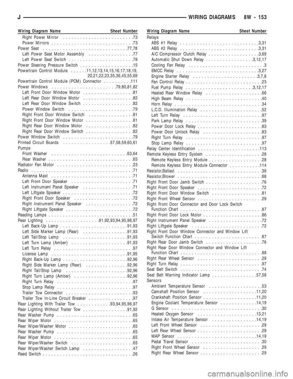
Wiring Diagram Name Sheet Number
Right Power Mirror.........................73
Power Mirrors.............................73
Power Seat..............................77,78
Left Power Seat Motor Assembly................77
Left Power Seat Switch.......................78
Power Steering Pressure Switch...................15
Powertrain Control Module......11,12,13,14,15,16,17,18,19,
20,21,22,23,35,36,45,55,69
Powertrain Control Module (PCM) Connector..........111
Power Windows.......................79,80,81,82
Left Front Door Window Motor..................81
Left Rear Door Window Motor..................82
Left Rear Door Window Switch..................82
Power Window Switch.......................79
Right Front Door Window Switch................81
Right Front Door Window Motor.................81
Right Rear Door Window Motor.................82
Right Rear Door Window Switch.................82
Power Window Switch.........................79
Printed Circuit Boards.................57,58,59,60,61
Pumps
Front Washer...........................63,64
Rear Washer..............................65
Radiator Fan Motor...........................23
Radio....................................71
Antenna Mast.............................71
Left Front Door Speaker......................71
Left Instrument Panel Speaker..................71
Left Liftgate Speaker.........................72
Right Front Door Speaker.....................72
Right Instrument Panel Speaker.................72
Right Liftgate Speaker........................72
Reading Lamps..............................51
Rear Lighting...................91,92,93,94,95,96,97
Left Back-Up Lamp........................91,93
Left Side Marker Lamp (Rear)................91,93
Left Tail/Stop Lamp.......................91,93
Left Turn Lamp (Amber)....................91,93
Left Turn Relay............................97
License Lamp...........................91,95
Right Back-Up Lamp.......................92,96
Right Side Marker Lamp (Rear)...............92,96
Right Tail/Stop Lamp......................92,96
Right Turn Lamp (Amber)...................92,96
Right Turn Relay...........................97
Stop Lamp Relay...........................97
Trailer Tow Connector........................93
Trailer Tow In-Line Circuit Breaker................97
Rear Lighting With Trailer Tow............93,94,95,96,97
Rear Lighting Without Trailer Tow................91,92
Rear Washer Pump...........................65
Rear Wiper Motor............................65
Rear Wiper/Washer Motor.......................65
Rear Washer Pump...........................65
Rear Wiper Motor............................65
Rear Wiper/Washer Switch......................65
Rear Wiper/Washer Switch Lamp..................47
Reed Switch................................26Wiring Diagram Name Sheet Number
Relays
ABS #1 Relay............................3,31
ABS #2 Relay............................3,31
A/C Compressor Clutch Relay..................3,69
Automatic Shut Down Relay.................3,12,17
Cooling Fan Relay...........................3
EMCC Relay.............................3,27
Engine Starter Relay.......................3,7,8
Fan Control Relay...........................23
Fuel Pump Relay........................3,12,17
Heated Rear Window Relay....................66
High Beam Relay...........................40
Horn Relay...............................34
L.C.D. Illumination Relay......................52
Left Turn Relay............................97
Park Lamp Relay...........................39
Power Door Lock Relay.......................83
Power Door Unlock Relay.....................83
Right Turn Relay...........................97
Stop Lamp Relay...........................97
Relay Center Identification......................113
Remote Keyless Entry System....................28
Remote Keyless Entry Module...................28
Remote Keyless Entry Module Connector...........114
Resistor,Ballast..............................39
Resistor,Blower..............................68
Right Front Door Jamb Switch....................76
Right Front Door Speaker.......................72
Right Front Door Window Switch..................81
Right Front Wheel Sensor.......................29
Right Front Door Connector and Door Lock Switch
Function Chart.............................87
Right Front Door Lock Motor.....................86
Right Instrument Panel Speaker...................72
Right Liftgate Speaker.........................72
Right Front Door Window Connector and Window Lift
Switch Function Chart........................87
Right Rear Door Jamb Switch....................76
Right Rear Door Window Connector and Window Lift
Function Chart.............................88
Right Rear Wheel Sensor.......................29
Right Turn Relay.............................97
Seat Belt Switch.............................74
Seat Belt Warning Indicator Lamp................57,58
Sensors
Ambient Temperature Sensor...................53
Camshaft Position Sensor...................11,20
Crankshaft Position Sensor...................11,20
Engine Coolant Temperature Sensor.............14,19
G Sensor................................30
Heated Oxygen Sensor.....................13,21
Intake Air Temperature Sensor................14,19
Left Front Wheel Sensor......................29
Left Rear Wheel Sensor.......................29
MAP Sensor............................14,19
Pedal Travel Sensor.........................30
Right Front Wheel Sensor.....................29
Right Rear Wheel Sensor......................29
JWIRING DIAGRAMS 8W - 153