1994 JEEP CHEROKEE wheel torque
[x] Cancel search: wheel torquePage 1086 of 1784
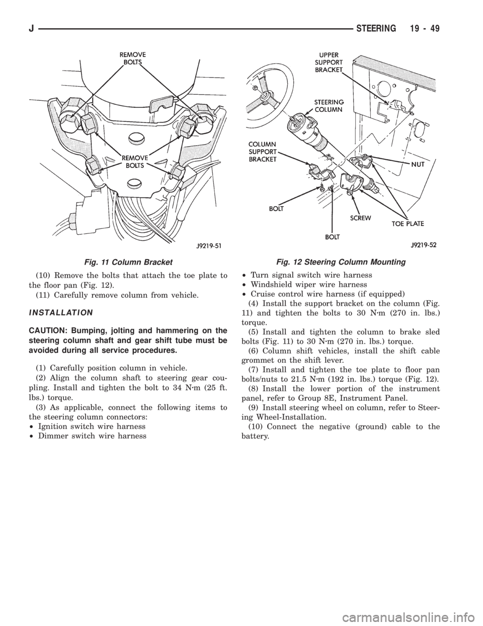
(10) Remove the bolts that attach the toe plate to
the floor pan (Fig. 12).
(11) Carefully remove column from vehicle.
INSTALLATION
CAUTION: Bumping, jolting and hammering on the
steering column shaft and gear shift tube must be
avoided during all service procedures.
(1) Carefully position column in vehicle.
(2) Align the column shaft to steering gear cou-
pling. Install and tighten the bolt to 34 Nzm (25 ft.
lbs.) torque.
(3) As applicable, connect the following items to
the steering column connectors:
²Ignition switch wire harness
²Dimmer switch wire harness²Turn signal switch wire harness
²Windshield wiper wire harness
²Cruise control wire harness (if equipped)
(4) Install the support bracket on the column (Fig.
11) and tighten the bolts to 30 Nzm (270 in. lbs.)
torque.
(5) Install and tighten the column to brake sled
bolts (Fig. 11) to 30 Nzm (270 in. lbs.) torque.
(6) Column shift vehicles, install the shift cable
grommet on the shift lever.
(7) Install and tighten the toe plate to floor pan
bolts/nuts to 21.5 Nzm (192 in. lbs.) torque (Fig. 12).
(8) Install the lower portion of the instrument
panel, refer to Group 8E, Instrument Panel.
(9) Install steering wheel on column, refer to Steer-
ing Wheel-Installation.
(10) Connect the negative (ground) cable to the
battery.
Fig. 11 Column BracketFig. 12 Steering Column Mounting
JSTEERING 19 - 49
Page 1095 of 1784
(8) Align the turn signal switch in the housing and
secure the switch with the attaching screws. Tighten
the screws to 4 Nzm (35 in. lbs.) torque.
(9) Install the dimmer switch actuator arm.
Tighten the attaching screws to 4 Nzm (35 in. lbs.)
torque.
(10) If equipped, install the cruise control wire har-
ness. Install the turn signal stalk by pushing it
straight into the column.
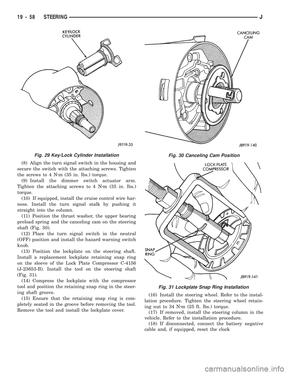
(11) Position the thrust washer, the upper bearing
preload spring and the canceling cam on the steering
shaft (Fig. 30).
(12) Place the turn signal switch in the neutral
(OFF) position and install the hazard warning switch
knob.
(13) Position the lockplate on the steering shaft.
Install a replacement lockplate retaining snap ring
on the sleeve of the Lock Plate Compressor C-4156
(J-23653-B). Install the tool on the steering shaft
(Fig. 31).
(14) Compress the lockplate with the compressor
tool and position the retaining snap ring in the steer-
ing shaft groove.
(15) Ensure that the retaining snap ring is com-
pletely seated in the groove before removing the tool.
Remove the tool and install the lockplate cover.(16) Install the steering wheel. Refer to the instal-
lation procedure. Tighten the steering wheel retain-
ing nut to 34 Nzm (25 ft. lbs.) torque.
(17) If removed, install the steering column in the
vehicle. Refer to the installation procedure.
(18) If disconnected, connect the battery negative
cable and, if equipped, reset the clock
Fig. 30 Canceling Cam Position
Fig. 31 Lockplate Snap Ring Installation
Fig. 29 Key/Lock Cylinder Installation
19 - 58 STEERINGJ
Page 1103 of 1784
(33 in. lbs.) torque. Thread the hazard warning
switch knob into the switch and pull the knob out-
ward.
(38) Install and seat the upper bearing race in the
key/lock cylinder housing.
(39) Install the upper bearing preload spring, the
canceling cam and the lockplate.
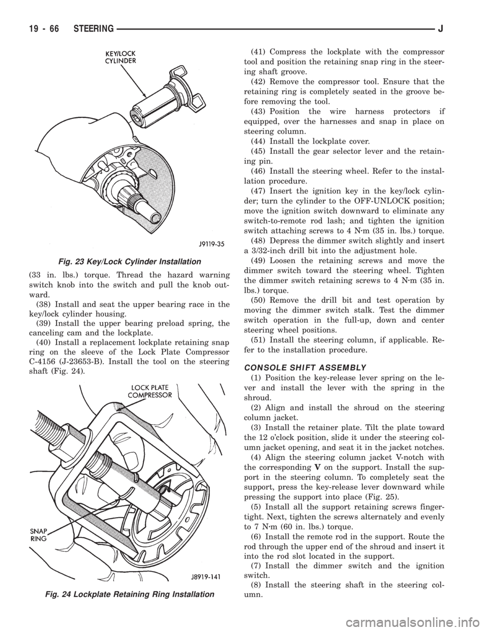
(40) Install a replacement lockplate retaining snap
ring on the sleeve of the Lock Plate Compressor
C-4156 (J-23653-B). Install the tool on the steering
shaft (Fig. 24).(41) Compress the lockplate with the compressor
tool and position the retaining snap ring in the steer-
ing shaft groove.
(42) Remove the compressor tool. Ensure that the
retaining ring is completely seated in the groove be-
fore removing the tool.
(43) Position the wire harness protectors if
equipped, over the harnesses and snap in place on
steering column.
(44) Install the lockplate cover.
(45) Install the gear selector lever and the retain-
ing pin.
(46) Install the steering wheel. Refer to the instal-
lation procedure.
(47) Insert the ignition key in the key/lock cylin-
der; turn the cylinder to the OFF-UNLOCK position;
move the ignition switch downward to eliminate any
switch-to-remote rod lash; and tighten the ignition
switch attaching screws to 4 Nzm (35 in. lbs.) torque.
(48) Depress the dimmer switch slightly and insert
a 3/32-inch drill bit into the adjustment hole.
(49) Loosen the retaining screws and move the
dimmer switch toward the steering wheel. Tighten
the dimmer switch retaining screws to 4 Nzm (35 in.
lbs.) torque.
(50) Remove the drill bit and test operation by
moving the dimmer switch stalk. Test the dimmer
switch operation in the full-up, down and center
steering wheel positions.
(51) Install the steering column, if applicable. Re-
fer to the installation procedure.
CONSOLE SHIFT ASSEMBLY
(1) Position the key-release lever spring on the le-
ver and install the lever with the spring in the
shroud.
(2) Align and install the shroud on the steering
column jacket.
(3) Install the retainer plate. Tilt the plate toward
the 12 o'clock position, slide it under the steering col-
umn jacket opening, and seat it in the jacket notches.
(4) Align the steering column jacket V-notch with
the correspondingVon the support. Install the sup-
port in the steering column. To completely seat the
support, press the key-release lever downward while
pressing the support into place (Fig. 25).
(5) Install all the support retaining screws finger-
tight. Next, tighten the screws alternately and evenly
to7Nzm (60 in. lbs.) torque.
(6) Install the remote rod in the support. Route the
rod through the upper end of the shroud and insert it
into the rod slot located in the support.
(7) Install the dimmer switch and the ignition
switch.
(8) Install the steering shaft in the steering col-
umn.
Fig. 23 Key/Lock Cylinder Installation
Fig. 24 Lockplate Retaining Ring Installation
19 - 66 STEERINGJ
Page 1105 of 1784
(25) Install the windshield wiper wire harness and
switch. Route the wire harness down through steer-
ing column jacket.
(26) If equipped, install the cruise control wire har-
ness. Install the turn signal stalk by pushing it
straight into the column.
(27) Insert the hazard warning knob in the hazard
warning switch and press it inward. Align and install
the turn signal switch retaining screws. Ensure that
the turn signal switch is properly seated before tight-
ening the screws. Tighten the screws to 4 Nzm (33 in.
lbs.) torque. Thread the hazard warning switch knob
into the switch and pull the knob outward.
(28) Install and seat the upper bearing race in the
key/lock cylinder housing.
(29) Install the upper bearing preload spring, the
canceling cam and the lockplate.
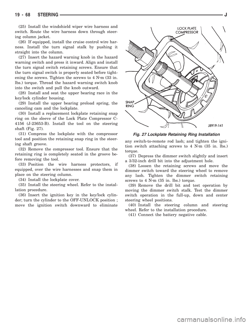
(30) Install a replacement lockplate retaining snap
ring on the sleeve of the Lock Plate Compressor C-
4156 (J-23653-B). Install the tool on the steering
shaft (Fig. 27).
(31) Compress the lockplate with the compressor
tool and position the retaining snap ring in the steer-
ing shaft groove.
(32) Remove the compressor tool. Ensure that the
retaining ring is completely seated in the groove be-
fore removing the tool.
(33) Position the wire harness protectors, if
equipped, over the wire harnesses and snap them in
place on the steering column.
(34) Install the lockplate cover.
(35) Install the steering wheel. Refer to the instal-
lation procedure.
(36) Insert the ignition key in the key/lock cylin-
der; turn the cylinder to the OFF-UNLOCK position ;
move the ignition switch downward to eliminateany switch-to-remote rod lash; and tighten the igni-
tion switch attaching screws to 4 Nzm (35 in. lbs.)
torque.
(37) Depress the dimmer switch slightly and insert
a 3/32-inch drill bit into the adjustment hole.
(38) Loosen the retaining screws and move the
dimmer switch toward the steering wheel to remove
any lash. Tighten the dimmer switch retaining
screws to 4 Nzm (35 in. lbs.) torque.
(39) Remove the drill bit and test operation by
moving the dimmer switch stalk. Test the dimmer
switch operation in the full-up, down and center
steering wheel positions.
(40) Install the steering column and steering
wheel. Refer to the installation procedure.
(41) Connect the battery negative cable.
Fig. 27 Lockplate Retaining Ring Installation
19 - 68 STEERINGJ
Page 1106 of 1784
STEERING RHD
GENERAL SERVICE PROCEDURE INFORMATION
Right hand drive service procedures and torque
specifications involving steering; linkage, gear and
column are the same as left hand drive vehicles ex-
cept where shown. Refer to appropriate service proce-
dures regarding each component in the system.
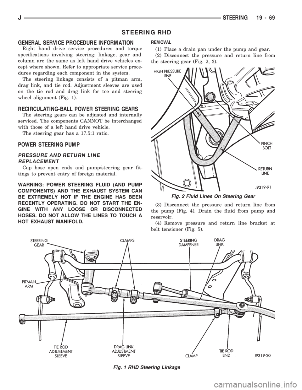
The steering linkage consists of a pitman arm,
drag link, and tie rod. Adjustment sleeves are used
on the tie rod and drag link for toe and steering
wheel alignment (Fig. 1).
RECIRCULATING-BALL POWER STEERING GEARS
The steering gears can be adjusted and internally
serviced. The components CANNOT be interchanged
with those of a left hand drive vehicle.
The steering gear has a 17.5:1 ratio.
POWER STEERING PUMP
PRESSURE AND RETURN LINE
REPLACEMENT
Cap hose open ends and pump/steering gear fit-
tings to prevent entry of foreign material.
WARNING: POWER STEERING FLUID (AND PUMP
COMPONENTS) AND THE EXHAUST SYSTEM CAN
BE EXTREMELY HOT IF THE ENGINE HAS BEEN
RECENTLY OPERATING. DO NOT START THE EN-
GINE WITH ANY LOOSE OR DISCONNECTED
HOSES. DO NOT ALLOW THE LINES TO TOUCH A
HOT EXHAUST MANIFOLD.REMOVAL
(1) Place a drain pan under the pump and gear.
(2) Disconnect the pressure and return line from
the steering gear (Fig. 2, 3).
(3) Disconnect the pressure and return line from
the pump (Fig. 4). Drain the fluid from pump and
reservoir.
(4) Remove pressure and return line bracket at
belt tensioner (Fig. 5).
Fig. 1 RHD Steering Linkage
Fig. 2 Fluid Lines On Steering Gear
JSTEERING 19 - 69
Page 1116 of 1784
(12) Align transfer case and transmission shafts
and install transfer case. Tighten transfer case-to-
transmission nuts/bolts to 35 Nzm (26 ft. lbs.) torque.
(13) Remove jack stand from under engine and re-
position jack under transmission. Then remove trans-
mission jack.
(14) Connect transfer case vent hose and shift link-
age. Check and adjust linkage if necessary.
(15) Connect transmission and transfer case vent
hoses.
(16) Connect backup light switch wires.
(17) Connect vehicle speed sensor wires.
(18) Install and connect crankshaft position sensor
if equipped.
(19) Install rear crossmember, or skid plate (Fig. 5).
On XJ, tighten crossmember-to-frame bolts to 41 Nzm
(31 ft. lbs.) torque. Then tighten transmission-to-rear
support bolts/nuts to 45 Nzm (33 ft. lbs.) torque. On YJ,
tighten bolts/nuts to indicated torque (Fig. 5).
(20) Align and install front/rear propeller shafts.
Tighten shaft U-joint clamp bolts to 19 Nzm (170 in.
lbs.) torque.
(21) On XJ, install skid plate, if removed. Tighten
bolts to 42 Nzm (31 ft. lbs.) torque. Tighten stud nuts
to 17 Nzm (150 in. lbs.) torque.
(22) Top off transmission and transfer case lubri-
cant levels.
(23) Lower vehicle.
TRANSMISSION DISASSEMBLY AND OVERHAUL
ADAPTER HOUSING AND FRONT BEARING
RETAINER REMOVAL
(1) Drain transmission lubricant.
(2) Remove concentric bearing.
(3) Remove clutch housing bolts and remove housing.
(4) On 2-wheel drive models, remove vehicle speed
sensor, speedometer adapter and speedometer driven
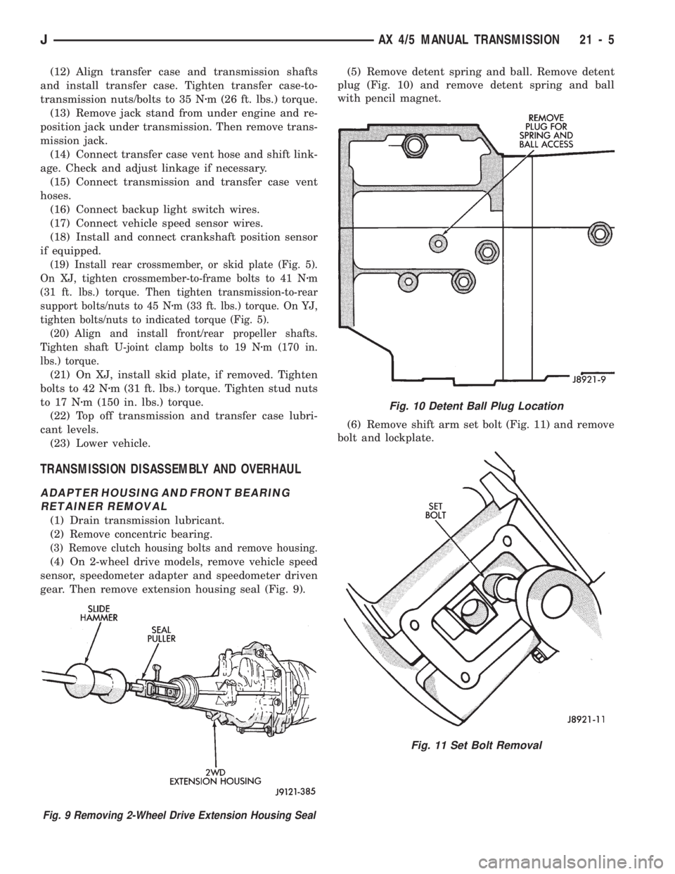
gear. Then remove extension housing seal (Fig. 9).(5) Remove detent spring and ball. Remove detent
plug (Fig. 10) and remove detent spring and ball
with pencil magnet.
(6) Remove shift arm set bolt (Fig. 11) and remove
bolt and lockplate.
Fig. 10 Detent Ball Plug Location
Fig. 11 Set Bolt Removal
Fig. 9 Removing 2-Wheel Drive Extension Housing Seal
JAX 4/5 MANUAL TRANSMISSION 21 - 5
Page 1141 of 1784
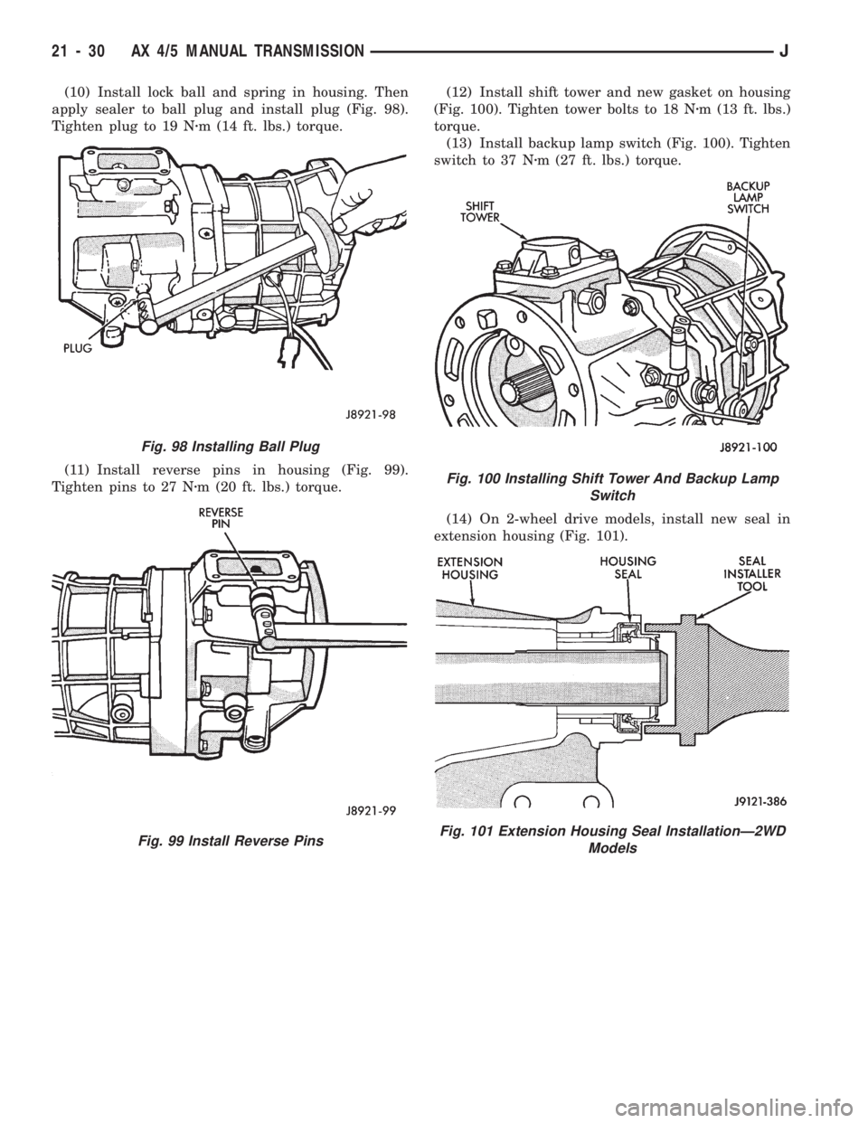
(10) Install lock ball and spring in housing. Then
apply sealer to ball plug and install plug (Fig. 98).
Tighten plug to 19 Nzm (14 ft. lbs.) torque.
(11) Install reverse pins in housing (Fig. 99).
Tighten pins to 27 Nzm (20 ft. lbs.) torque.(12) Install shift tower and new gasket on housing
(Fig. 100). Tighten tower bolts to 18 Nzm (13 ft. lbs.)
torque.
(13) Install backup lamp switch (Fig. 100). Tighten
switch to 37 Nzm (27 ft. lbs.) torque.
(14) On 2-wheel drive models, install new seal in
extension housing (Fig. 101).
Fig. 98 Installing Ball Plug
Fig. 99 Install Reverse Pins
Fig. 100 Installing Shift Tower And Backup Lamp
Switch
Fig. 101 Extension Housing Seal InstallationÐ2WD
Models
21 - 30 AX 4/5 MANUAL TRANSMISSIONJ
Page 1147 of 1784
(10) Remove jack from under transmission and
mount transfer case on jack.
(11) Align transfer case and transmission shafts
and install transfer case. Tighten transfer case-to-
transmission nuts/bolts to 35 Nzm (26 ft. lbs.) torque.
(12) Move jack stand from under engine and repo-
sition it under transmission. Then remove transmis-
sion jack.
(13) Connect transfer case vacuum hoses and link-
age. Check and adjust linkage if necessary.
(14) Connect transmission and transfer case vent
hoses and backup light switch wires.
(15) Install clutch sleeve cylinder.
(16) Connect vehicle speed sensor and wires.
(17) On XJ, install rear crossmember and attach
cushion and bracket. Tighten crossmember-to-frame
bolts to 41 Nzm (30 ft. lbs.) torque. Tighten transmis-
sion-to-rear cushion and bracket bolts/nuts to 45 Nzm
(33 ft. lbs.) torque.
(18) On YJ, install rear cushion and bracket and
skid plate. Tighten attaching bolts/nuts to indicated
torque (Fig. 1).
(19) Align and install front/rear propeller shafts.
Tighten shaft U-joint clamp bolts to 19 Nzm (170 in.
lbs.) torque.
(20) On XJ, install skid plate if removed. Tighten
bolts to 42 Nzm (31 ft. lbs.) torque. Tighten stud nuts
to 17 Nzm (150 in. lbs.) torque.
(21) Top off transmission and transfer lubricant
levels.
(22) Remove supports and lower vehicle.
TRANSMISSION DISASSEMBLY AND OVERHAUL
ADAPTER/EXTENSION HOUSING REMOVAL
(1) Remove release bearing, fork, retainer clip and
clutch housing from transmission. Also remove shift
lever if not previously removed.
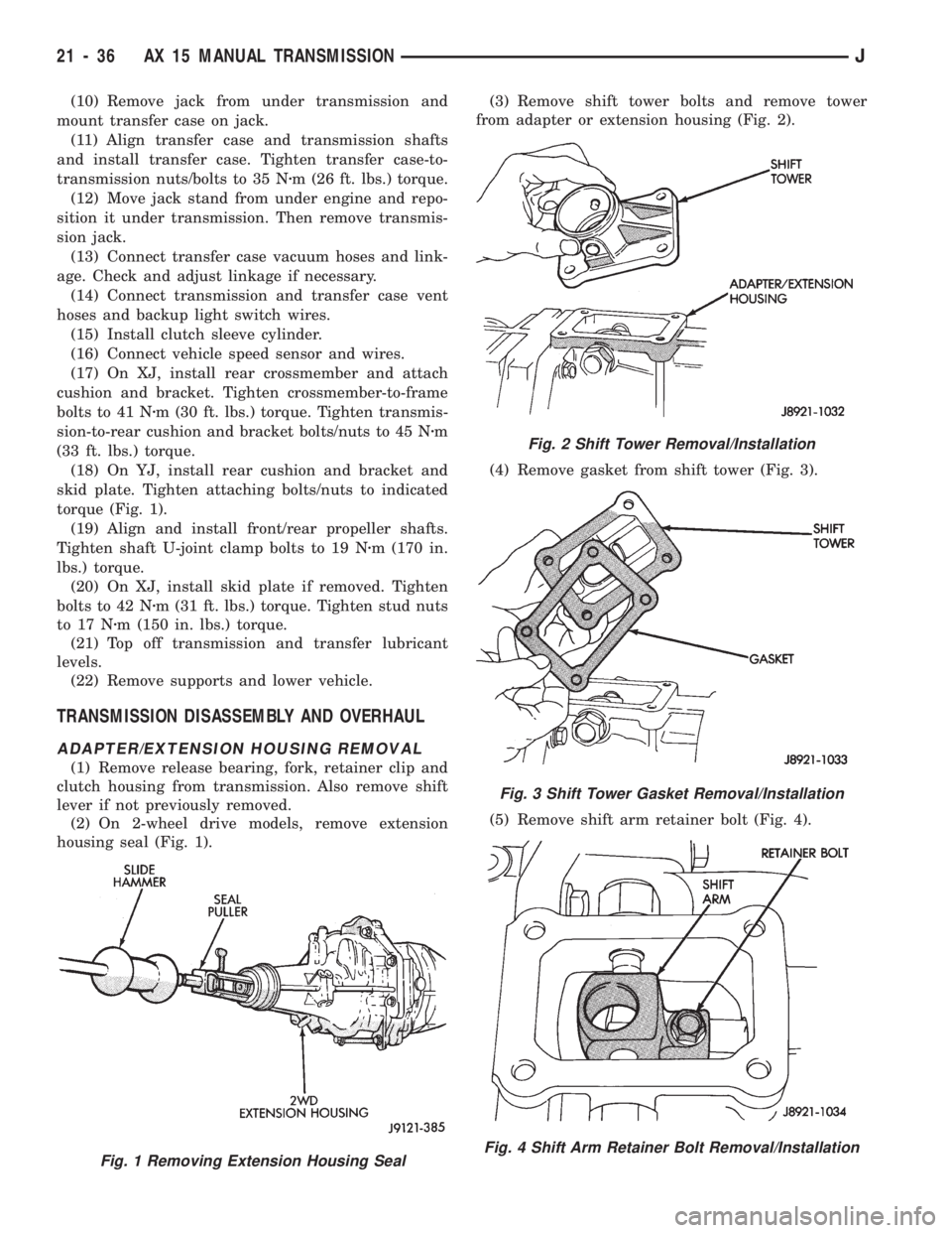
(2) On 2-wheel drive models, remove extension
housing seal (Fig. 1).(3) Remove shift tower bolts and remove tower
from adapter or extension housing (Fig. 2).
(4) Remove gasket from shift tower (Fig. 3).
(5) Remove shift arm retainer bolt (Fig. 4).
Fig. 1 Removing Extension Housing Seal
Fig. 2 Shift Tower Removal/Installation
Fig. 3 Shift Tower Gasket Removal/Installation
Fig. 4 Shift Arm Retainer Bolt Removal/Installation
21 - 36 AX 15 MANUAL TRANSMISSIONJ