1994 JEEP CHEROKEE radiator
[x] Cancel search: radiatorPage 978 of 1784
MULTI-PORT FUEL INJECTION (MFI)ÐCOMPONENT DESCRIPTION/SYSTEM
OPERATION
INDEX
page page
Air Conditioning (A/C) Clutch RelayÐPCM Output.24
Air Conditioning (A/C) ControlsÐPCM Input.... 19
Auto Shut Down (ASD) RelayÐPCM Output.... 24
Automatic Shut Down (ASD) SenseÐPCM Input . 19
Battery VoltageÐPCM Input................ 19
Brake SwitchÐPCM Input.................. 20
Camshaft Position SensorÐPCM Input........ 20
Crankshaft Position SensorÐPCM Input....... 20
Data Link ConnectorÐPCM Input............ 20
Data Link ConnectorÐPCM Output........... 24
EMR LampÐPCM Output.................. 24
Engine Coolant Temperature SensorÐPCM Input . 21
Extended Idle SwitchÐPCM Input............ 21
Fuel InjectorsÐPCM Output................ 25
Fuel Pressure Regulator................... 30
Fuel Pump RelayÐPCM Output............. 25
Fuel Rail............................... 30
General Information....................... 17
Generator FieldÐPCM Output............... 25
Generator LampÐPCM Output.............. 25
Idle Air Control (IAC) MotorÐPCM Output...... 25
Ignition Circuit SenseÐPCM Input............ 21
Ignition CoilÐPCM Output.................. 26Intake Air Temperature SensorÐPCM Input.... 20
Malfunction Indicator LampÐPCM Output...... 26
Manifold Absolute Pressure (MAP) SensorÐ
PCM Input............................ 21
Open Loop/Closed Loop Modes of Operation . . . 27
Overdrive/Override Switch.................. 22
Oxygen (O2S) SensorÐPCM Input........... 22
Park/Neutral SwitchÐPCM Input............. 22
Power Ground........................... 22
Power Steering Pressure SwitchÐPCM Input . . . 22
Powertrain Control Module (PCM)............ 18
Radiator Fan RelayÐPCM Output............ 26
SCI ReceiveÐPCM Input.................. 22
SCI TransmitÐPCM Output................. 26
Sensor ReturnÐPCM Input................. 23
Shift IndicatorÐPCM Output................ 26
Speed ControlÐPCM Input................. 23
Speed ControlÐPCM Output................ 27
TachometerÐPCM Output.................. 27
Throttle Body............................ 29
Throttle Position Sensor (TPS)ÐPCM Input..... 23
Torque Converter Clutch RelayÐPCM Output . . . 27
Vehicle Speed SensorÐPCM Input........... 23
GENERAL INFORMATION
All 2.5L 4 cylinder and 4.0L 6 cylinder engines are
equipped with sequential Multi-Port Fuel Injection
(MFI). The MFI system provides precise air/fuel ra-
tios for all driving conditions.
The Powertrain Control Module (PCM) operates
the fuel system. The PCM was formerly referred to
as the SBEC or engine controller. The PCM is a pre-
programmed, dual microprocessor digital computer.
It regulates ignition timing, air-fuel ratio, emission
control devices, charging system, speed control, air
conditioning compressor clutch engagement and idle
speed. The PCM can adapt its programming to meet
changing operating conditions.
Powertrain Control Module (PCM) Inputsrep-
resent the instantaneous engine operating conditions.
Air-fuel mixture and ignition timing calibrations for
various driving and atmospheric conditions are pre-
programmed into the PCM. The PCM monitors and
analyzes various inputs. It then computes engine fuel
and ignition timing requirements based on these in-
puts. Fuel delivery control and ignition timing will
then be adjusted accordingly.
Other inputs to the PCM are provided by the brake
light switch, air conditioning select switch and the
speed control switches. All inputs to the PCM are
converted into signals.
Electrically operated fuel injectors spray fuel in
precise metered amounts into the intake port directlyabove the intake valve. The injectors are fired in a
specific sequence by the PCM. The PCM maintains
an air/fuel ratio of 14.7 to 1 by constantly adjusting
injector pulse width. Injector pulse width is the
length of time that the injector opens and sprays fuel
into the chamber. The PCM adjusts injector pulse
width by opening and closing the ground path to the
injector.
Manifold absolute pressure (air density) and engine
rpm (speed) are the primary inputs that determine
fuel injector pulse width. The PCM also monitors
other inputs when adjusting air-fuel ratio.
Inputs That Effect Fuel Injector Pulse Width
²Exhaust gas oxygen content
²Engine coolant temperature
²Manifold absolute pressure (MAP)
²Engine speed
²Throttle position
²Battery voltage
²Air conditioning selection
²Transmission gear selection (automatic transmis-
sions only)
²Speed control
The powertrain control module (PCM) adjusts igni-
tion timing by controlling ignition coil operation. The
ignition coil receives battery voltage when the igni-
tion key is in the run or starter position. The PCM
provides a ground for the ignition coil. The coil dis-
JFUEL SYSTEM 14 - 17
Page 987 of 1784
ing the IAC motor pintle in and out of the air control
passage. The IAC motor is positioned when the igni-
tion key is turned to the On position.
A (factory adjusted) set screw is used to mechani-
cally limit the position of the throttle body throttle
plate.Never attempt to adjust the engine idle
speed using this screw.All idle speed functions are
controlled by the PCM.
IGNITION COILÐPCM OUTPUT
System voltage is supplied to the ignition coil pos-
itive terminal. The powertrain control module (PCM)
operates the ignition coil.Base (initial) ignition
timing is not adjustable.The PCM adjusts ignition
timing to meet changing engine operating conditions.
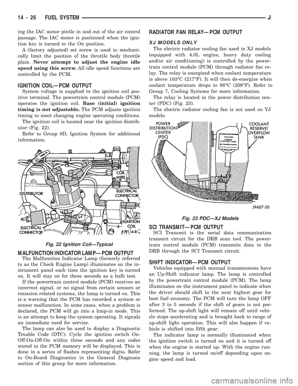
The ignition coil is located near the ignition distrib-
utor (Fig. 22).
Refer to Group 8D, Ignition System for additional
information.
MALFUNCTION INDICATOR LAMPÐPCM OUTPUT
The Malfunction Indicator Lamp (formerly referred
to as the Check Engine Lamp) illuminates on the in-
strument panel each time the ignition key is turned
on. It will stay on for three seconds as a bulb test.
If the powertrain control module (PCM) receives an
incorrect signal, or no signal from certain sensors or
emission related systems, the lamp is turned on. This
is a warning that the PCM has recorded a system or
sensor malfunction. In some cases, when a problem is
declared, the PCM will go into a limp-in mode. This
is an attempt to keep the system operating. It signals
an immediate need for service.
The lamp can also be used to display a Diagnostic
Trouble Code (DTC). Cycle the ignition switch On-
Off-On-Off-On within three seconds and any codes
stored in the PCM memory will be displayed. This is
done in a series of flashes representing digits. Refer
to On-Board Diagnostics in the General Diagnosis
section of this group for more information.
RADIATOR FAN RELAYÐPCM OUTPUT
XJ MODELS ONLY
The electric radiator cooling fan used in XJ models
(equipped with 4.0L engine, heavy duty cooling
and/or air conditioning) is controlled by the power-
train control module (PCM) through radiator fan re-
lay. The relay is energized when coolant temperature
is above 103ÉC (217ÉF). It will then de-energize when
coolant temperature drops to 98ÉC (208ÉF). Refer to
Group 7, Cooling Systems for more information.
The relay is located in the power distribution cen-
ter (PDC) (Fig. 23).
The electric radiator cooling fan is not used on YJ
models.
SCI TRANSMITÐPCM OUTPUT
SCI Transmit is the serial data communication
transmit circuit for the DRB scan tool. The power-
train control module (PCM) transmits data to the
DRB through the SCI Transmit circuit.
SHIFT INDICATORÐPCM OUTPUT
Vehicles equipped with manual transmissions have
an Up-Shift indicator lamp. The lamp is controlled
by the powertrain control module (PCM). The lamp
illuminates on the instrument panel to indicate when
the driver should shift to the next highest gear for
best fuel economy. The PCM will turn the lamp OFF
after 3 to 5 seconds if the shift of gears is not per-
formed. The up-shift light will remain off until vehi-
cle stops accelerating and is brought back to range of
up-shift light operation. This will also happen if ve-
hicle is shifted into fifth gear.
The indicator lamp is normally illuminated when
the ignition switch is turned on and it is turned off
when the engine is started up. With the engine run-
ning, the lamp is turned on/off depending upon en-
gine speed and load.
Fig. 23 PDCÐXJ Models
Fig. 22 Ignition CoilÐTypical
14 - 26 FUEL SYSTEMJ
Page 993 of 1784
MULTI-PORT FUEL INJECTION (MFI)ÐGENERAL DIAGNOSIS
INDEX
page page
Automatic Shutdown (ASD) Relay Testing...... 43
Camshaft Position Sensor Test.............. 43
Crankshaft Position Sensor Test............. 44
Diagnostic Trouble Code (DTC).............. 51
DRB Scan Tool.......................... 51
Engine Coolant Temperature Sensor Test...... 43
Extended Idle Switch Test.................. 45
Fuel Pump Relay Testing.................. 44
Fuel System Pressure Test................. 48
General Information....................... 32
Idle Air Control Motor Test................. 46
Injector Test............................ 48
Intake Air Temperature Sensor Test.......... 43Manifold Absolute Pressure (MAP) Sensor Test . 44
On-Board Diagnostics (OBD)................ 48
Oxygen Sensor (O2S) Heating Element Test.... 45
Powertrain Control Module (PCM) 60-Way
Connector............................ 38
RelaysÐOperation/Testing.................. 47
Starter Motor Relay Test................... 48
System Schematics....................... 38
Throttle Position Sensor (TPS) Test.......... 45
Torque Converter Clutch Relay Test.......... 45
Vehicle Speed Sensor Test................. 45
Visual Inspection......................... 32
GENERAL INFORMATION
All 2.5L 4 cylinder and 4.0L 6 cylinder engines are
equipped with sequential Multi-Port Fuel Injection
(MFI). The MFI system provides precise air/fuel ra-
tios for all driving conditions.
VISUAL INSPECTION
A visual inspection for loose, disconnected, or incor-
rectly routed wires and hoses should be made. This
should be done before attempting to diagnose or ser-
vice the fuel injection system. A visual check will
help spot these faults and save unnecessary test and
diagnostic time. A thorough visual inspection will in-
clude the following checks:
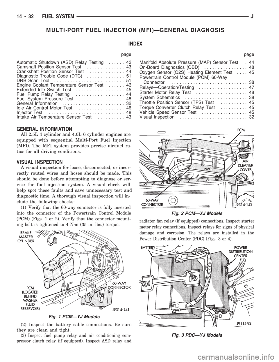
(1) Verify that the 60-way connector is fully inserted
into the connector of the Powertrain Control Module
(PCM) (Figs. 1 or 2). Verify that the connector mount-
ing bolt is tightened to 4 Nzm (35 in. lbs.) torque.
(2) Inspect the battery cable connections. Be sure
they are clean and tight.
(3) Inspect fuel pump relay and air conditioning com-
pressor clutch relay (if equipped). Inspect ASD relay andradiator fan relay (if equipped) connections. Inspect starter
motor relay connections. Inspect relays for signs of physical
damage and corrosion. The relays are installed in the
Power Distribution Center (PDC) (Figs. 3 or 4).
Fig. 1 PCMÐYJ Models
Fig. 2 PCMÐXJ Models
Fig. 3 PDCÐYJ Models
14 - 32 FUEL SYSTEMJ
Page 996 of 1784
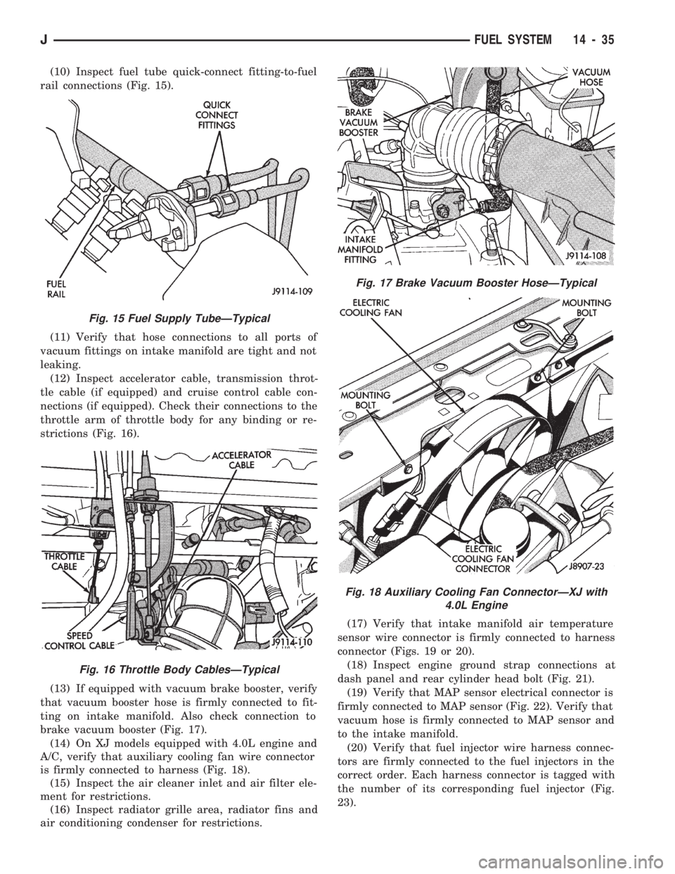
(10) Inspect fuel tube quick-connect fitting-to-fuel
rail connections (Fig. 15).
(11) Verify that hose connections to all ports of
vacuum fittings on intake manifold are tight and not
leaking.
(12) Inspect accelerator cable, transmission throt-
tle cable (if equipped) and cruise control cable con-
nections (if equipped). Check their connections to the
throttle arm of throttle body for any binding or re-
strictions (Fig. 16).
(13) If equipped with vacuum brake booster, verify
that vacuum booster hose is firmly connected to fit-
ting on intake manifold. Also check connection to
brake vacuum booster (Fig. 17).
(14) On XJ models equipped with 4.0L engine and
A/C, verify that auxiliary cooling fan wire connector
is firmly connected to harness (Fig. 18).
(15) Inspect the air cleaner inlet and air filter ele-
ment for restrictions.
(16) Inspect radiator grille area, radiator fins and
air conditioning condenser for restrictions.(17) Verify that intake manifold air temperature
sensor wire connector is firmly connected to harness
connector (Figs. 19 or 20).
(18) Inspect engine ground strap connections at
dash panel and rear cylinder head bolt (Fig. 21).
(19) Verify that MAP sensor electrical connector is
firmly connected to MAP sensor (Fig. 22). Verify that
vacuum hose is firmly connected to MAP sensor and
to the intake manifold.
(20) Verify that fuel injector wire harness connec-
tors are firmly connected to the fuel injectors in the
correct order. Each harness connector is tagged with
the number of its corresponding fuel injector (Fig.
23).
Fig. 15 Fuel Supply TubeÐTypical
Fig. 16 Throttle Body CablesÐTypical
Fig. 17 Brake Vacuum Booster HoseÐTypical
Fig. 18 Auxiliary Cooling Fan ConnectorÐXJ with
4.0L Engine
JFUEL SYSTEM 14 - 35
Page 1013 of 1784
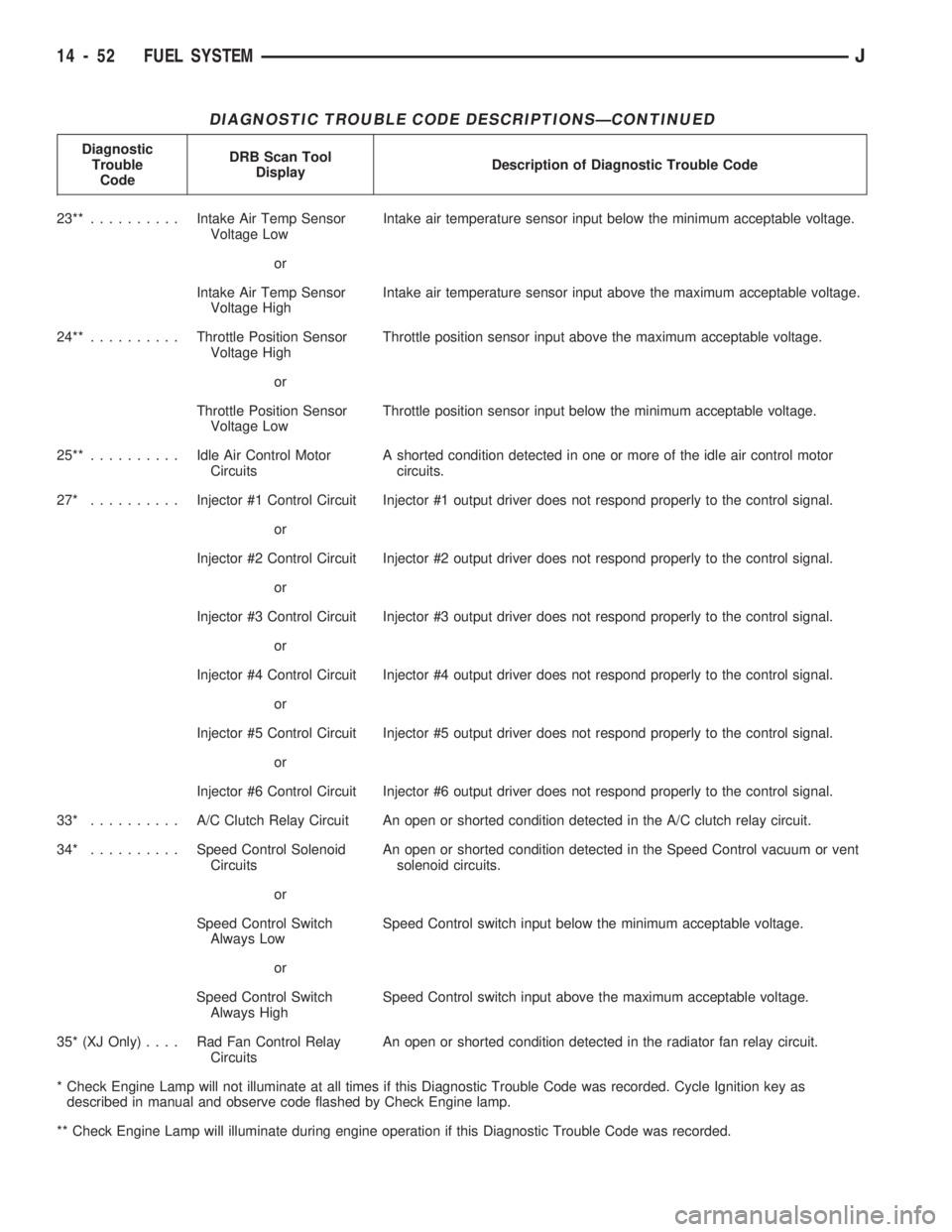
DIAGNOSTIC TROUBLE CODE DESCRIPTIONSÐCONTINUED
Diagnostic
Trouble
CodeDRB Scan Tool
DisplayDescription of Diagnostic Trouble Code
23**..........Intake Air Temp Sensor
Voltage LowIntake air temperature sensor input below the minimum acceptable voltage.
or
Intake Air Temp Sensor
Voltage HighIntake air temperature sensor input above the maximum acceptable voltage.
24**..........Throttle Position Sensor
Voltage HighThrottle position sensor input above the maximum acceptable voltage.
or
Throttle Position Sensor
Voltage LowThrottle position sensor input below the minimum acceptable voltage.
25**..........Idle Air Control Motor
CircuitsA shorted condition detected in one or more of the idle air control motor
circuits.
27* ..........Injector #1 Control Circuit Injector #1 output driver does not respond properly to the control signal.
or
Injector #2 Control Circuit Injector #2 output driver does not respond properly to the control signal.
or
Injector #3 Control Circuit Injector #3 output driver does not respond properly to the control signal.
or
Injector #4 Control Circuit Injector #4 output driver does not respond properly to the control signal.
or
Injector #5 Control Circuit Injector #5 output driver does not respond properly to the control signal.
or
Injector #6 Control Circuit Injector #6 output driver does not respond properly to the control signal.
33* .......... A/CClutch Relay Circuit An open or shorted condition detected in the A/C clutch relay circuit.
34* ..........Speed Control Solenoid
CircuitsAn open or shorted condition detected in the Speed Control vacuum or vent
solenoid circuits.
or
Speed Control Switch
Always LowSpeed Control switch input below the minimum acceptable voltage.
or
Speed Control Switch
Always HighSpeed Control switch input above the maximum acceptable voltage.
35* (XJ Only).... RadFanControl Relay
CircuitsAn open or shorted condition detected in the radiator fan relay circuit.
* Check Engine Lamp will not illuminate at all times if this Diagnostic Trouble Code was recorded. Cycle Ignition key as
described in manual and observe code flashed by Check Engine lamp.
** Check Engine Lamp will illuminate during engine operation if this Diagnostic Trouble Code was recorded.
14 - 52 FUEL SYSTEMJ
Page 1216 of 1784
(10) Install speedometer adapter clamp and retain-
ing screw. Tighten clamp screw to 10-12 Nzm (90-110
in. lbs.) torque.
(11) Connect wires to vehicle speed sensor.
(12) Lower vehicle and top off transmission fluid
level if necessary.
SPEEDOMETER COMPONENT REMOVAL
(TWO-PIECE SENSOR)
(1) Raise vehicle.
(2) Disconnect speed sensor wires.
(3) Remove bolt attaching vehicle speed sensor to
sensor adapter. Then slide sensor out of adapter.
(4) Inspect speed sensor mounting area in sensor
adapter. If transmission fluid is found in this area,
oil seal in metal speedometer adapter is leaking and
will have to be replaced.
(5) Remove speedometer adapter clamp bolt and
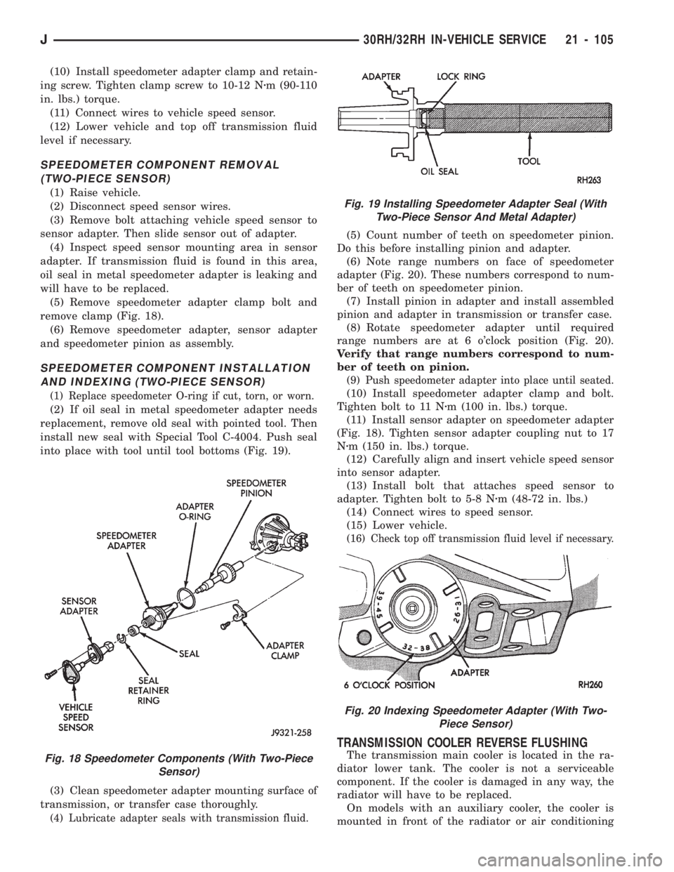
remove clamp (Fig. 18).
(6) Remove speedometer adapter, sensor adapter
and speedometer pinion as assembly.
SPEEDOMETER COMPONENT INSTALLATION
AND INDEXING (TWO-PIECE SENSOR)
(1) Replace speedometer O-ring if cut, torn, or worn.
(2) If oil seal in metal speedometer adapter needs
replacement, remove old seal with pointed tool. Then
install new seal with Special Tool C-4004. Push seal
into place with tool until tool bottoms (Fig. 19).
(3) Clean speedometer adapter mounting surface of
transmission, or transfer case thoroughly.
(4) Lubricate adapter seals with transmission fluid.
(5) Count number of teeth on speedometer pinion.
Do this before installing pinion and adapter.
(6) Note range numbers on face of speedometer
adapter (Fig. 20). These numbers correspond to num-
ber of teeth on speedometer pinion.
(7) Install pinion in adapter and install assembled
pinion and adapter in transmission or transfer case.
(8) Rotate speedometer adapter until required
range numbers are at 6 o'clock position (Fig. 20).
Verify that range numbers correspond to num-
ber of teeth on pinion.
(9) Push speedometer adapter into place until seated.
(10) Install speedometer adapter clamp and bolt.
Tighten bolt to 11 Nzm (100 in. lbs.) torque.
(11) Install sensor adapter on speedometer adapter
(Fig. 18). Tighten sensor adapter coupling nut to 17
Nzm (150 in. lbs.) torque.
(12) Carefully align and insert vehicle speed sensor
into sensor adapter.
(13) Install bolt that attaches speed sensor to
adapter. Tighten bolt to 5-8 Nzm (48-72 in. lbs.)
(14) Connect wires to speed sensor.
(15) Lower vehicle.
(16) Check top off transmission fluid level if necessary.
TRANSMISSION COOLER REVERSE FLUSHING
The transmission main cooler is located in the ra-
diator lower tank. The cooler is not a serviceable
component. If the cooler is damaged in any way, the
radiator will have to be replaced.
On models with an auxiliary cooler, the cooler is
mounted in front of the radiator or air conditioningFig. 18 Speedometer Components (With Two-Piece
Sensor)
Fig. 19 Installing Speedometer Adapter Seal (With
Two-Piece Sensor And Metal Adapter)
Fig. 20 Indexing Speedometer Adapter (With Two-
Piece Sensor)
J30RH/32RH IN-VEHICLE SERVICE 21 - 105
Page 1217 of 1784
condenser. The auxiliary cooler is a serviceable com-
ponent and can be repaired if necessary.
The main and auxiliary coolers should be thor-
oughly reverse flushed if a transmission failure
contaminates the fluid. Reverse flushing the cooler
and lines will prevent sludge and particles from
flowing back into the transmission after repair.
The same flushing procedure is used for main and
auxiliary coolers. Pressure equipment is preferred for
reverse flushing. However, reverse flushing can be
performed using hand operated equipment as de-
scribed in the following procedure.
REVERSE FLUSHING PROCEDURE
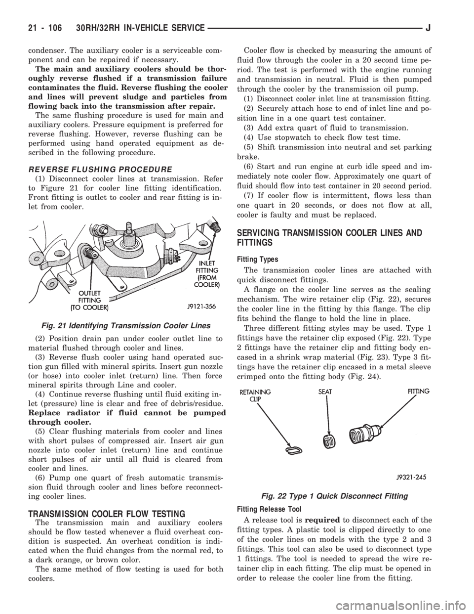
(1) Disconnect cooler lines at transmission. Refer
to Figure 21 for cooler line fitting identification.
Front fitting is outlet to cooler and rear fitting is in-
let from cooler.
(2) Position drain pan under cooler outlet line to
material flushed through cooler and lines.
(3) Reverse flush cooler using hand operated suc-
tion gun filled with mineral spirits. Insert gun nozzle
(or hose) into cooler inlet (return) line. Then force
mineral spirits through Line and cooler.
(4) Continue reverse flushing until fluid exiting in-
let (pressure) line is clear and free of debris/residue.
Replace radiator if fluid cannot be pumped
through cooler.
(5) Clear flushing materials from cooler and lines
with short pulses of compressed air. Insert air gun
nozzle into cooler inlet (return) line and continue
short pulses of air until all fluid is cleared from
cooler and lines.
(6) Pump one quart of fresh automatic transmis-
sion fluid through cooler and lines before reconnect-
ing cooler lines.
TRANSMISSION COOLER FLOW TESTING
The transmission main and auxiliary coolers
should be flow tested whenever a fluid overheat con-
dition is suspected. An overheat condition is indi-
cated when the fluid changes from the normal red, to
a dark orange, or brown color.
The same method of flow testing is used for both
coolers.Cooler flow is checked by measuring the amount of
fluid flow through the cooler in a 20 second time pe-
riod. The test is performed with the engine running
and transmission in neutral. Fluid is then pumped
through the cooler by the transmission oil pump.
(1) Disconnect cooler inlet line at transmission fitting.
(2) Securely attach hose to end of inlet line and po-
sition line in a one quart test container.
(3) Add extra quart of fluid to transmission.
(4) Use stopwatch to check flow test time.
(5) Shift transmission into neutral and set parking
brake.
(6) Start and run engine at curb idle speed and im-
mediately note cooler flow. Approximately one quart of
fluid should flow into test container in 20 second period.
(7) If cooler flow is intermittent, flows less than
one quart in 20 seconds, or does not flow at all,
cooler is faulty and must be replaced.
SERVICING TRANSMISSION COOLER LINES AND
FITTINGS
Fitting Types
The transmission cooler lines are attached with
quick disconnect fittings.
A flange on the cooler line serves as the sealing
mechanism. The wire retainer clip (Fig. 22), secures
the cooler line in the fitting by this flange. The clip
fits behind the flange to hold the line in place.
Three different fitting styles may be used. Type 1
fittings have the retainer clip exposed (Fig. 22). Type
2 fittings have the retainer clip and fitting body en-
cased in a shrink wrap material (Fig. 23). Type 3 fit-
tings have the retainer clip encased in a metal sleeve
crimped onto the fitting body (Fig. 24).
Fitting Release Tool
A release tool isrequiredto disconnect each of the
fitting types. A plastic tool is clipped directly to one
of the cooler lines on models with the type 2 and 3
fittings. This tool can also be used to disconnect type
1 fittings. The tool is needed to spread the wire re-
tainer clip in each fitting. The clip must be opened in
order to release the cooler line from the fitting.
Fig. 21 Identifying Transmission Cooler Lines
Fig. 22 Type 1 Quick Disconnect Fitting
21 - 106 30RH/32RH IN-VEHICLE SERVICEJ
Page 1218 of 1784
Fitting And Cooler Line Service
The cooler lines and quick disconnect fittings are
NOT serviceable. Damaged fittings or cooler lines
are to be replaced as assemblies.
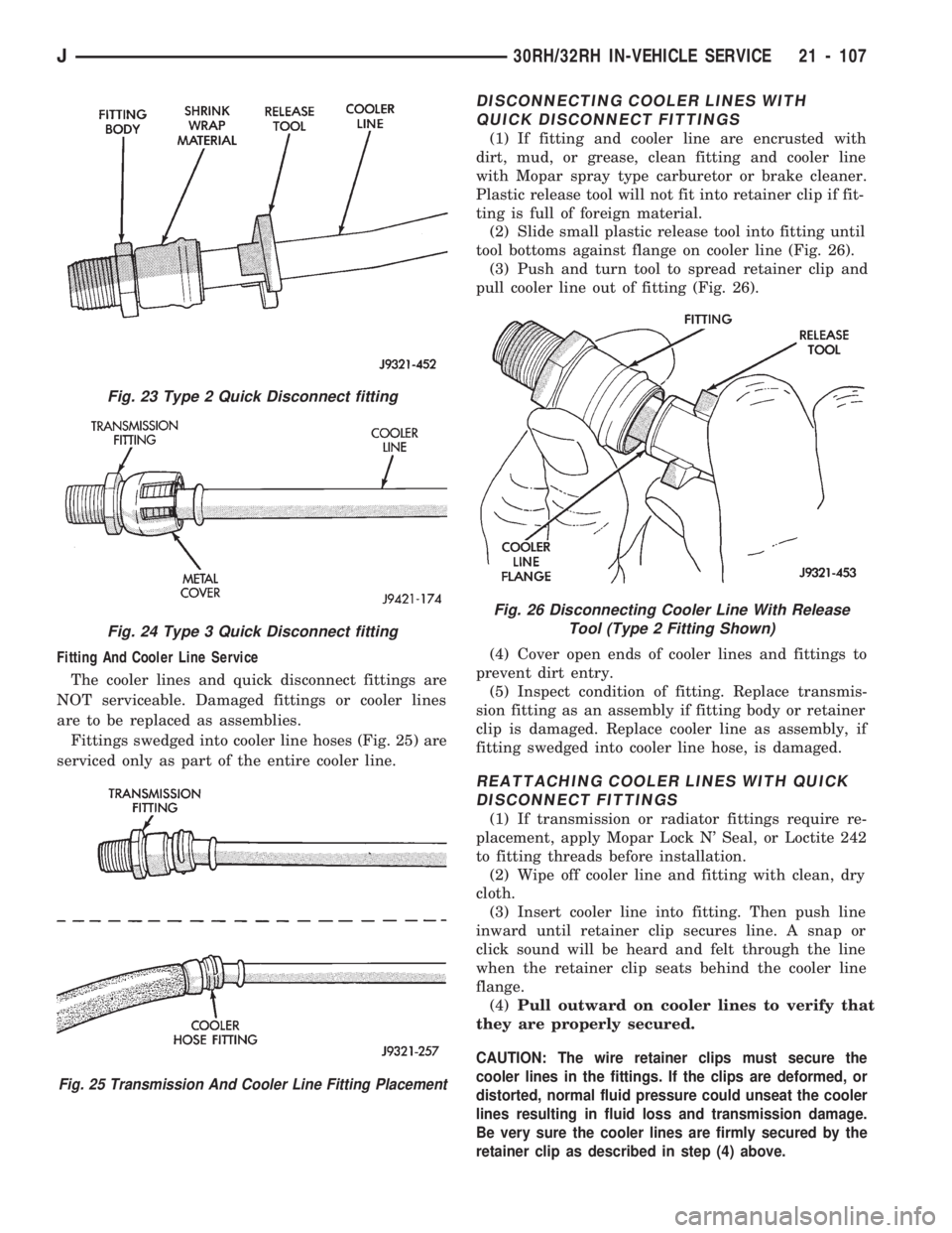
Fittings swedged into cooler line hoses (Fig. 25) are
serviced only as part of the entire cooler line.
DISCONNECTING COOLER LINES WITH
QUICK DISCONNECT FITTINGS
(1) If fitting and cooler line are encrusted with
dirt, mud, or grease, clean fitting and cooler line
with Mopar spray type carburetor or brake cleaner.
Plastic release tool will not fit into retainer clip if fit-
ting is full of foreign material.
(2) Slide small plastic release tool into fitting until
tool bottoms against flange on cooler line (Fig. 26).
(3) Push and turn tool to spread retainer clip and
pull cooler line out of fitting (Fig. 26).
(4) Cover open ends of cooler lines and fittings to
prevent dirt entry.
(5) Inspect condition of fitting. Replace transmis-
sion fitting as an assembly if fitting body or retainer
clip is damaged. Replace cooler line as assembly, if
fitting swedged into cooler line hose, is damaged.
REATTACHING COOLER LINES WITH QUICK
DISCONNECT FITTINGS
(1) If transmission or radiator fittings require re-
placement, apply Mopar Lock N' Seal, or Loctite 242
to fitting threads before installation.
(2) Wipe off cooler line and fitting with clean, dry
cloth.
(3) Insert cooler line into fitting. Then push line
inward until retainer clip secures line. A snap or
click sound will be heard and felt through the line
when the retainer clip seats behind the cooler line
flange.
(4)Pull outward on cooler lines to verify that
they are properly secured.
CAUTION: The wire retainer clips must secure the
cooler lines in the fittings. If the clips are deformed, or
distorted, normal fluid pressure could unseat the cooler
lines resulting in fluid loss and transmission damage.
Be very sure the cooler lines are firmly secured by the
retainer clip as described in step (4) above.
Fig. 23 Type 2 Quick Disconnect fitting
Fig. 24 Type 3 Quick Disconnect fitting
Fig. 25 Transmission And Cooler Line Fitting Placement
Fig. 26 Disconnecting Cooler Line With Release
Tool (Type 2 Fitting Shown)
J30RH/32RH IN-VEHICLE SERVICE 21 - 107