1994 JEEP CHEROKEE engine oil
[x] Cancel search: engine oilPage 331 of 1784

Check the high-tension cable connections for good
contact at the ignition coil, distributor cap towers
and spark plugs. Terminals should be fully seated.
The terminals and spark plug covers should be in
good condition. Terminals should fit tightly to the ig-
nition coil, distributor cap and spark plugs. The
spark plug cover (boot) of the cable should fit tight
around the spark plug insulator. Loose cable connec-
tions can cause corrosion and increase resistance, re-
sulting in shorter cable service life.
Clean the high tension cables with a cloth moist-
ened with a nonflammable solvent and wipe dry.
Check for brittle or cracked insulation.
When testing secondary cables for damage with an
oscilloscope, follow the instructions of the equipment
manufacturer.
If an oscilloscope is not available, spark plug cables
may be tested as follows:
CAUTION: Do not leave any one spark plug cable
disconnected for longer than necessary during test-
ing. This may cause possible heat damage to the
catalytic converter. Total test time must not exceed
ten minutes.
With the engine not running, connect one end of a
test probe to a good ground. Start the engine and run
the other end of the test probe along the entire
length of all spark plug cables. If cables are cracked
or punctured, there will be a noticeable spark jump
from the damaged area to the test probe. The cable
running from the ignition coil to the distributor cap
can be checked in the same manner. Cracked, dam-
aged or faulty cables should be replaced with resis-
tance type cable. This can be identified by the words
ELECTRONIC SUPPRESSION printed on the cable
jacket.
Use an ohmmeter to test for open circuits, exces-
sive resistance or loose terminals. Remove the dis-
tributor cap from the distributor.Do not remove
cables from cap.Remove cable from spark plug.
Connect ohmmeter to spark plug terminal end of ca-
ble and to corresponding electrode in distributor cap.
Resistance should be 250 to 1000 Ohms per inch of
cable. If not, remove cable from distributor cap tower
and connect ohmmeter to the terminal ends of cable.
If resistance is not within specifications as found in
the Spark Plug Cable Resistance chart, replace the
cable. Test all spark plug cables in this manner.To test ignition coil-to-distributor cap cable, do not
remove the cable from the cap. Connect ohmmeter to
rotor button (center contact) of distributor cap and
terminal at ignition coil end of cable. If resistance is
not within specifications as found in the Spark Plug
Cable Resistance chart, remove the cable from the
distributor cap. Connect the ohmmeter to the termi-
nal ends of the cable. If resistance is not within spec-
ifications as found in the Spark Plug Cable
Resistance chart, replace the cable. Inspect the igni-
tion coil tower for cracks, burns or corrosion.
For removal and installation of spark plug cables,
refer to Spark Plug Secondary Cables in the Compo-
nent Removal/Installation section.
THROTTLE POSITION SENSOR TEST
To perform a complete test of this sensor and its
circuitry, refer to the DRB scan tool. Also refer to the
appropriate Powertrain Diagnostics Procedures man-
ual. To test the sensor only, refer to the following:
The throttle position sensor can be tested with a
digital voltmeter. The center terminal of the sensor
connector is the output terminal (Figs. 30 or 31).
SPARK PLUG CABLE RESISTANCE
Fig. 30 SensorÐ2.5L Engine
Fig. 31 SensorÐ4.0L Engine
8D - 18 IGNITION SYSTEMSJ
Page 333 of 1784
COMPONENT REMOVAL/INSTALLATION
INDEX
page page
Automatic Shut Down (ASD) Relay........... 20
Camshaft Position Sensor.................. 20
Crankshaft Position Sensor................. 21
Distributor.............................. 23
Engine Coolant Temperature Sensor.......... 22
General Information....................... 20
Ignition Coil............................. 26Intake Manifold Air Temperature Sensor....... 27
Manifold Absolute Pressure (MAP) Sensor..... 27
Oxygen (O2S) Sensor..................... 28
Powertrain Control Module (PCM)............ 28
Spark Plug Secondary Cables............... 29
Spark Plugs............................ 28
Throttle Position Sensor (TPS).............. 29
GENERAL INFORMATION
This section of the group, Component Removal/In-
stallation, will discuss the removal and installation
of ignition system components.
For basic ignition system diagnostics and service
adjustments, refer to the Diagnostics/Service Proce-
dures section of this group.
For system operation and component identification,
refer to the Component Identification/System Opera-
tion section of this group.
AUTOMATIC SHUT DOWN (ASD) RELAY
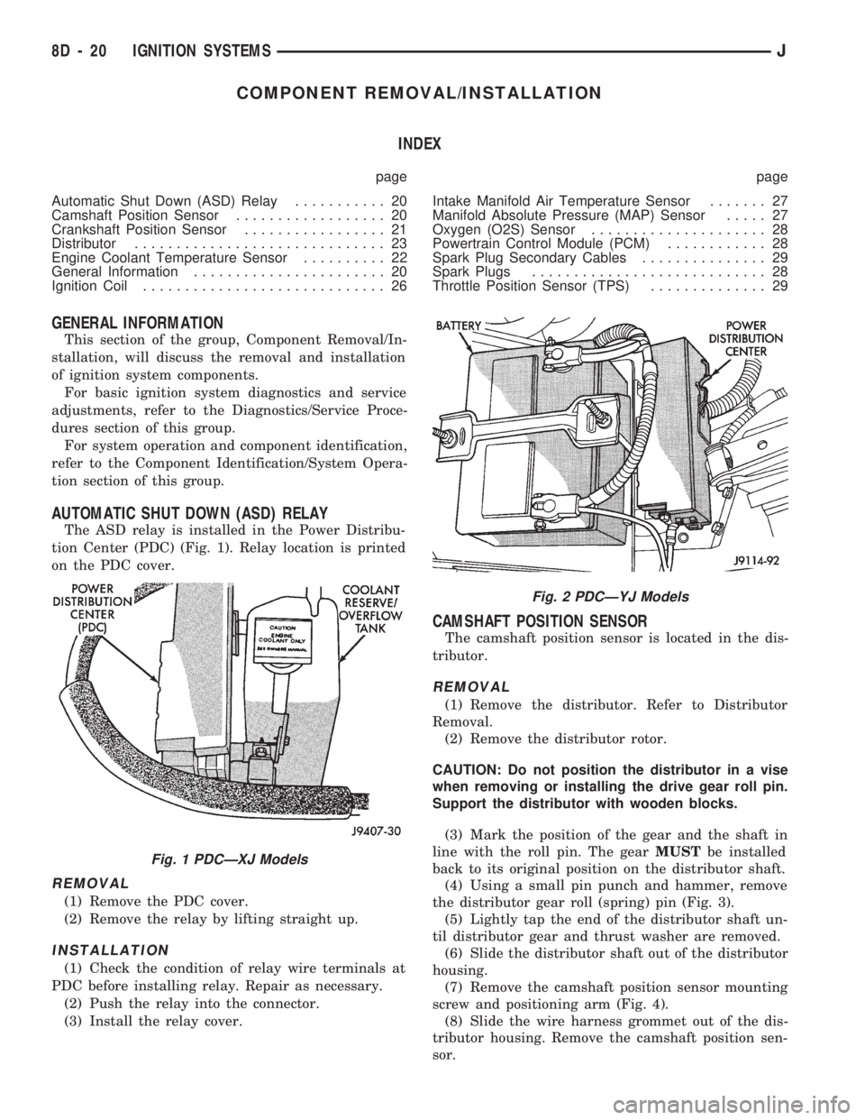
The ASD relay is installed in the Power Distribu-
tion Center (PDC) (Fig. 1). Relay location is printed
on the PDC cover.
REMOVAL
(1) Remove the PDC cover.
(2) Remove the relay by lifting straight up.
INSTALLATION
(1) Check the condition of relay wire terminals at
PDC before installing relay. Repair as necessary.
(2) Push the relay into the connector.
(3) Install the relay cover.
CAMSHAFT POSITION SENSOR
The camshaft position sensor is located in the dis-
tributor.
REMOVAL
(1) Remove the distributor. Refer to Distributor
Removal.
(2) Remove the distributor rotor.
CAUTION: Do not position the distributor in a vise
when removing or installing the drive gear roll pin.
Support the distributor with wooden blocks.
(3) Mark the position of the gear and the shaft in
line with the roll pin. The gearMUSTbe installed
back to its original position on the distributor shaft.
(4) Using a small pin punch and hammer, remove
the distributor gear roll (spring) pin (Fig. 3).
(5) Lightly tap the end of the distributor shaft un-
til distributor gear and thrust washer are removed.
(6) Slide the distributor shaft out of the distributor
housing.
(7) Remove the camshaft position sensor mounting
screw and positioning arm (Fig. 4).
(8) Slide the wire harness grommet out of the dis-
tributor housing. Remove the camshaft position sen-
sor.
Fig. 1 PDCÐXJ Models
Fig. 2 PDCÐYJ Models
8D - 20 IGNITION SYSTEMSJ
Page 336 of 1784
INSTALLATION
(1) Install coolant temperature sensor into the
thermostat housing. Tighten to 28 Nzm (21 ft. lbs.)
torque.
(2) Connect the wire connector.
(3) Fill the cooling system. Refer to group 7, Cool-
ing System.
DISTRIBUTOR
All distributors contain an internal oil seal that
prevents oil from entering the distributor housing.
The seal is not serviceable.
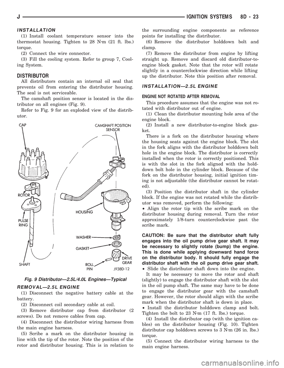
The camshaft position sensor is located in the dis-
tributor on all engines (Fig. 9).
Refer to Fig. 9 for an exploded view of the distrib-
utor.
REMOVALÐ2.5L ENGINE
(1) Disconnect the negative battery cable at the
battery.
(2) Disconnect coil secondary cable at coil.
(3) Remove distributor cap from distributor (2
screws). Do not remove cables from cap.
(4) Disconnect the distributor wiring harness from
the main engine harness.
(5) Scribe a mark on the distributor housing in
line with the tip of the rotor. Note the position of the
rotor and distributor housing. This is in relation tothe surrounding engine components as reference
points for installing the distributor.
(6) Remove the distributor holddown bolt and
clamp.
(7) Remove the distributor from engine by lifting
straight up. Remove and discard old distributor-to-
engine block gasket. Note that the rotor will rotate
slightly in a counterclockwise direction while lifting
up the distributor. Note this position after removal.
INSTALLATIONÐ2.5L ENGINE
ENGINE NOT ROTATED AFTER REMOVAL
This procedure assumes that the engine was not ro-
tated with distributor out of engine.
(1) Clean the distributor mounting hole area of the
engine block.
(2) Install a new distributor-to-engine block gas-
ket.
There is a fork on the distributor housing where
the housing seats against the engine block. The slot
in the fork aligns with the distributor holddown bolt
hole in the engine block. The distributor is correctly
installed when the rotor is correctly positioned. This
is with the slot in the fork aligned with the hold-
down bolt hole in the cylinder block. Because of the
fork on the distributor housing, initial ignition tim-
ing is not adjustable (the distributor cannot be rotat-
ed).
(3) Position the distributor shaft in the cylinder
block. If the engine was not rotated while the distrib-
utor was removed, perform the following:
²Align the rotor tip with the scribe mark on the
distributor housing during removal. Turn the rotor
approximately 1/8-turn counterclockwise past the
scribe mark.
CAUTION: Be sure that the distributor shaft fully
engages into the oil pump drive gear shaft. It may
be necessary to slightly rotate (bump) the engine.
This is done while applying downward hand force
on the distributor body. It should fully engage the
distributor shaft with the oil pump drive gear shaft.
²Slide the distributor shaft down into the engine.
It may be necessary to move the rotor and shaft
(slightly) to engage the distributor shaft with the slot
in the oil pump shaft. The same may have to be done
to engage the distributor gear with the camshaft
gear. However, the rotor should align with the scribe
mark when the distributor shaft is down in place.
²Install the distributor holddown clamp and bolt.
Tighten the bolt to 23 Nzm (17 ft. lbs.) torque.
(4) Install the distributor cap (with the ignition ca-
bles) on the distributor housing (Fig. 10). Tighten
distributor cap holddown screws to 3 Nzm (26 in. lbs.)
torque.
(5) Connect the distributor wiring harness to the
main engine harness.
Fig. 9 DistributorÐ2.5L/4.0L EnginesÐTypical
JIGNITION SYSTEMS 8D - 23
Page 337 of 1784
CAUTION: Do not puncture the spark plug cables or
boots to make the connection. Use proper adapters.
(6) Connect battery cable to battery.
ENGINE ROTATED AFTER REMOVAL
There is a fork on the distributor housing where
the housing seats against the engine block. The slot
in the fork aligns with the hole for the distributor
holddown bolt in the engine block. The distributor is
correctly installed when the rotor is correctly posi-
tioned. This is when the slot in the fork is aligned
with the hole for the distributor holddown bolt in the
cylinder block. Because of the fork on the distributor
housing, initial ignition timing is not adjustable (the
distributor cannot be rotated).
(1) If the engine was rotated while the distributor
was removed, it will be necessary to establish timing
according to following procedure:
²Remove the No. 1 spark plug. Hold a finger over
the spark plug hole and rotate the engine until com-
pression pressure is felt. Slowly continue to rotate
the engine. Do this until the timing index on vibra-
tion damper pulley aligns with top dead center (TDC)mark (0 degree) on timing degree scale. Always ro-
tate the engine in direction of normal rotation. Do
not turn the engine backward to align the timing
marks.
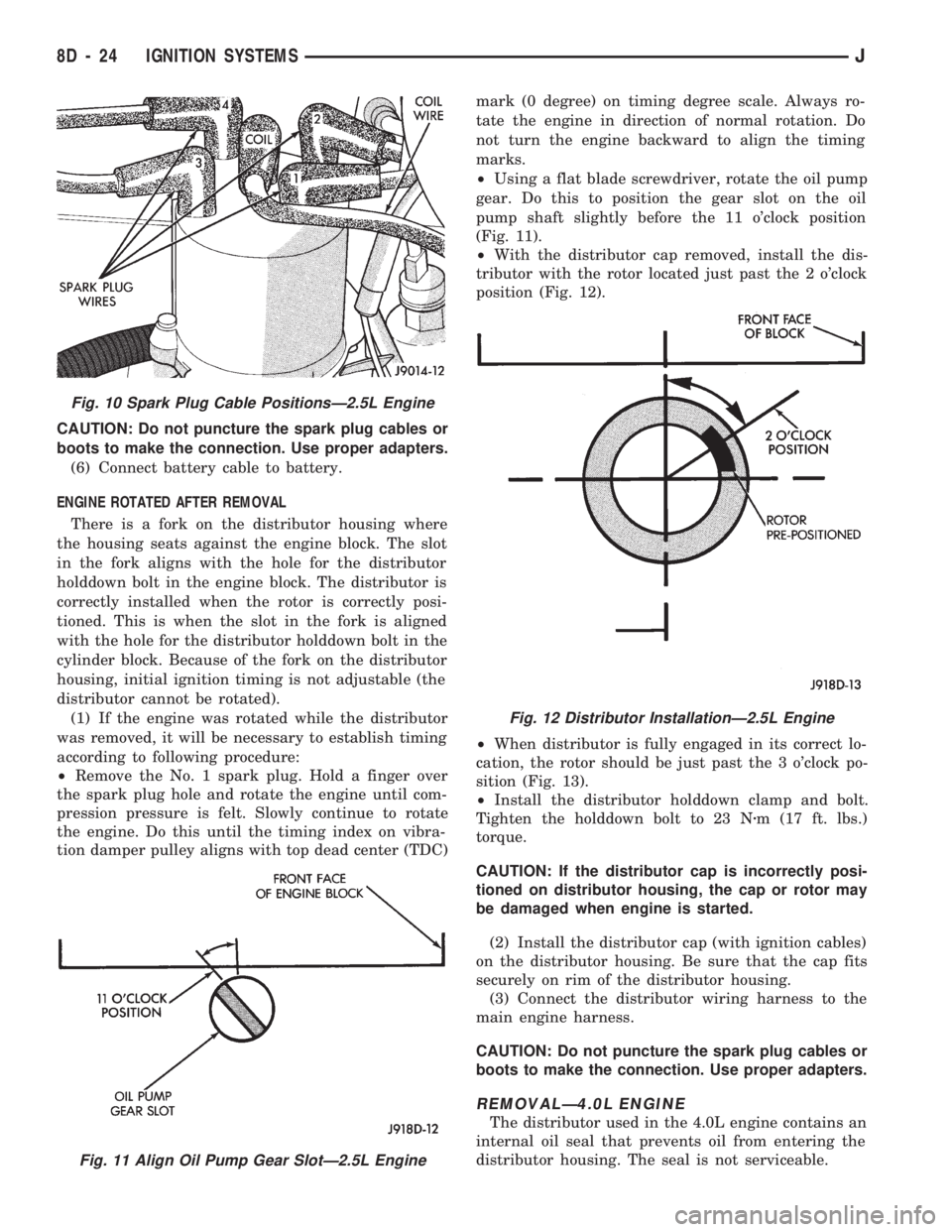
²Using a flat blade screwdriver, rotate the oil pump
gear. Do this to position the gear slot on the oil
pump shaft slightly before the 11 o'clock position
(Fig. 11).
²With the distributor cap removed, install the dis-
tributor with the rotor located just past the 2 o'clock
position (Fig. 12).
²When distributor is fully engaged in its correct lo-
cation, the rotor should be just past the 3 o'clock po-
sition (Fig. 13).
²Install the distributor holddown clamp and bolt.
Tighten the holddown bolt to 23 Nzm (17 ft. lbs.)
torque.
CAUTION: If the distributor cap is incorrectly posi-
tioned on distributor housing, the cap or rotor may
be damaged when engine is started.
(2) Install the distributor cap (with ignition cables)
on the distributor housing. Be sure that the cap fits
securely on rim of the distributor housing.
(3) Connect the distributor wiring harness to the
main engine harness.
CAUTION: Do not puncture the spark plug cables or
boots to make the connection. Use proper adapters.
REMOVALÐ4.0L ENGINE
The distributor used in the 4.0L engine contains an
internal oil seal that prevents oil from entering the
distributor housing. The seal is not serviceable.
Fig. 11 Align Oil Pump Gear SlotÐ2.5L Engine
Fig. 10 Spark Plug Cable PositionsÐ2.5L Engine
Fig. 12 Distributor InstallationÐ2.5L Engine
8D - 24 IGNITION SYSTEMSJ
Page 338 of 1784
The camshaft position sensor is located in the dis-
tributor on all engines (Fig. 9).
Refer to figure 9 for an exploded view of the dis-
tributor.
(1) Disconnect the negative battery cable at bat-
tery.
(2) On XJ models equipped with A/C, remove the
electrical cooling fan and shroud assembly from the
radiator. This will provide room to turn the engine
with a socket and ratchet using the vibration damper
bolt.
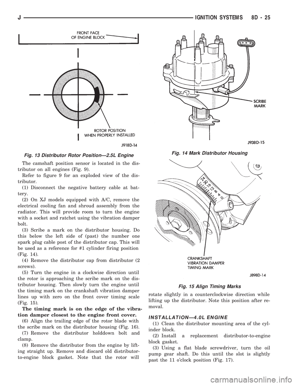
(3) Scribe a mark on the distributor housing. Do
this below the left side of (past) the number one
spark plug cable post of the distributor cap. This will
be used as a reference for #1 cylinder firing position
(Fig. 14).
(4) Remove the distributor cap from distributor (2
screws).
(5) Turn the engine in a clockwise direction until
the rotor is approaching the scribe mark on the dis-
tributor housing. Then slowly turn the engine until
the timing mark on the crankshaft vibration damper
lines up with zero on the front cover timing scale
(Fig. 15).
The timing mark is on the edge of the vibra-
tion damper closest to the engine front cover.
(6) Align the trailing edge of the rotor blade with
the scribe mark on the distributor housing (Fig. 16).
(7) Remove the distributor holddown bolt and
clamp.
(8) Remove the distributor from the engine by lift-
ing straight up. Remove and discard old distributor-
to-engine block gasket. Note that the rotor willrotate slightly in a counterclockwise direction while
lifting up the distributor. Note this position after re-
moval.
INSTALLATIONÐ4.0L ENGINE
(1) Clean the distributor mounting area of the cyl-
inder block.
(2) Install a replacement distributor-to-engine
block gasket.
(3) Using a flat blade screwdriver, turn the oil
pump gear shaft. Do this until the slot is slightly
past the 11 o'clock position (Fig. 17).
Fig. 13 Distributor Rotor PositionÐ2.5L EngineFig. 14 Mark Distributor Housing
Fig. 15 Align Timing Marks
JIGNITION SYSTEMS 8D - 25
Page 339 of 1784
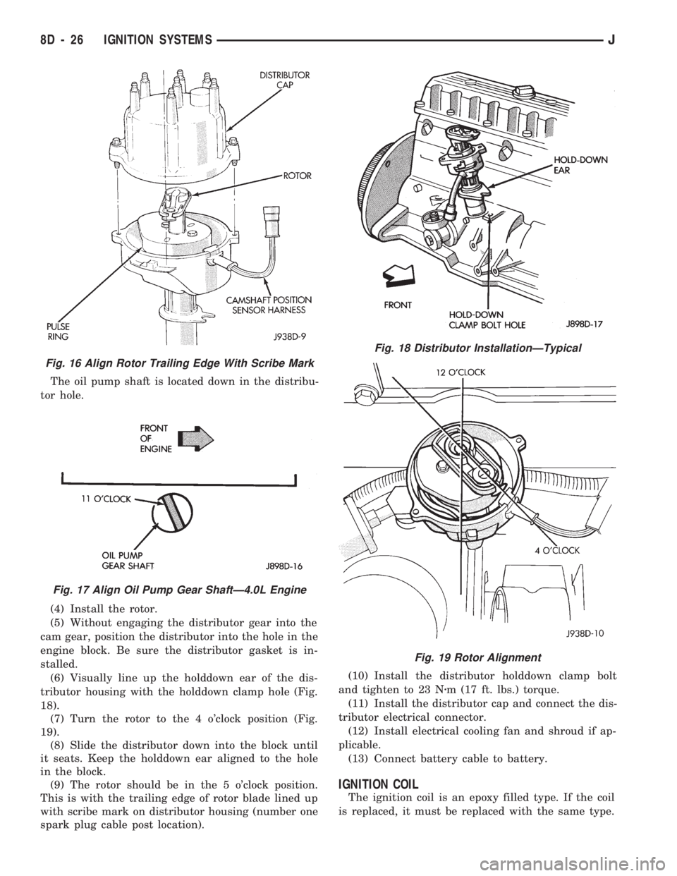
The oil pump shaft is located down in the distribu-
tor hole.
(4) Install the rotor.
(5) Without engaging the distributor gear into the
cam gear, position the distributor into the hole in the
engine block. Be sure the distributor gasket is in-
stalled.
(6) Visually line up the holddown ear of the dis-
tributor housing with the holddown clamp hole (Fig.
18).
(7) Turn the rotor to the 4 o'clock position (Fig.
19).
(8) Slide the distributor down into the block until
it seats. Keep the holddown ear aligned to the hole
in the block.
(9) The rotor should be in the 5 o'clock position.
This is with the trailing edge of rotor blade lined up
with scribe mark on distributor housing (number one
spark plug cable post location).(10) Install the distributor holddown clamp bolt
and tighten to 23 Nzm (17 ft. lbs.) torque.
(11) Install the distributor cap and connect the dis-
tributor electrical connector.
(12) Install electrical cooling fan and shroud if ap-
plicable.
(13) Connect battery cable to battery.
IGNITION COIL
The ignition coil is an epoxy filled type. If the coil
is replaced, it must be replaced with the same type.
Fig. 16 Align Rotor Trailing Edge With Scribe Mark
Fig. 17 Align Oil Pump Gear ShaftÐ4.0L Engine
Fig. 18 Distributor InstallationÐTypical
Fig. 19 Rotor Alignment
8D - 26 IGNITION SYSTEMSJ
Page 340 of 1784
REMOVAL
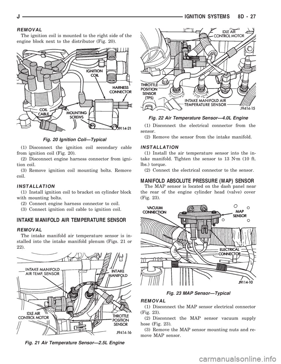
The ignition coil is mounted to the right side of the
engine block next to the distributor (Fig. 20).
(1) Disconnect the ignition coil secondary cable
from ignition coil (Fig. 20).
(2) Disconnect engine harness connector from igni-
tion coil.
(3) Remove ignition coil mounting bolts. Remove
coil.
INSTALLATION
(1) Install ignition coil to bracket on cylinder block
with mounting bolts.
(2) Connect engine harness connector to coil.
(3) Connect ignition coil cable to ignition coil.
INTAKE MANIFOLD AIR TEMPERATURE SENSOR
REMOVAL
The intake manifold air temperature sensor is in-
stalled into the intake manifold plenum (Figs. 21 or
22).(1) Disconnect the electrical connector from the
sensor.
(2) Remove the sensor from the intake manifold.
INSTALLATION
(1) Install the air temperature sensor into the in-
take manifold. Tighten the sensor to 13 Nzm (10 ft.
lbs.) torque.
(2) Connect the electrical connector to the sensor.
MANIFOLD ABSOLUTE PRESSURE (MAP) SENSOR
The MAP sensor is located on the dash panel near
the rear of the engine cylinder head (valve) cover
(Fig. 23).
REMOVAL
(1) Disconnect the MAP sensor electrical connector
(Fig. 23).
(2) Disconnect the MAP sensor vacuum supply
hose (Fig. 23).
(3) Remove the MAP sensor mounting nuts and re-
move MAP sensor.
Fig. 20 Ignition CoilÐTypical
Fig. 21 Air Temperature SensorÐ2.5L Engine
Fig. 22 Air Temperature SensorÐ4.0L Engine
Fig. 23 MAP SensorÐTypical
JIGNITION SYSTEMS 8D - 27
Page 341 of 1784
INSTALLATION
(1) Install MAP sensor to dash panel and secure
with mounting nuts.
(2) Install the MAP sensor vacuum supply hose.
(3) Connect the MAP sensor electrical connector.
OXYGEN (O2S) SENSOR
For diagnostics and removal/installation proce-
dures, refer to Group 14, Fuel Systems, in this man-
ual.
POWERTRAIN CONTROL MODULE (PCM)
The PCM was formerly referred to as the SBEC or
engine controller.
XJ MODELS
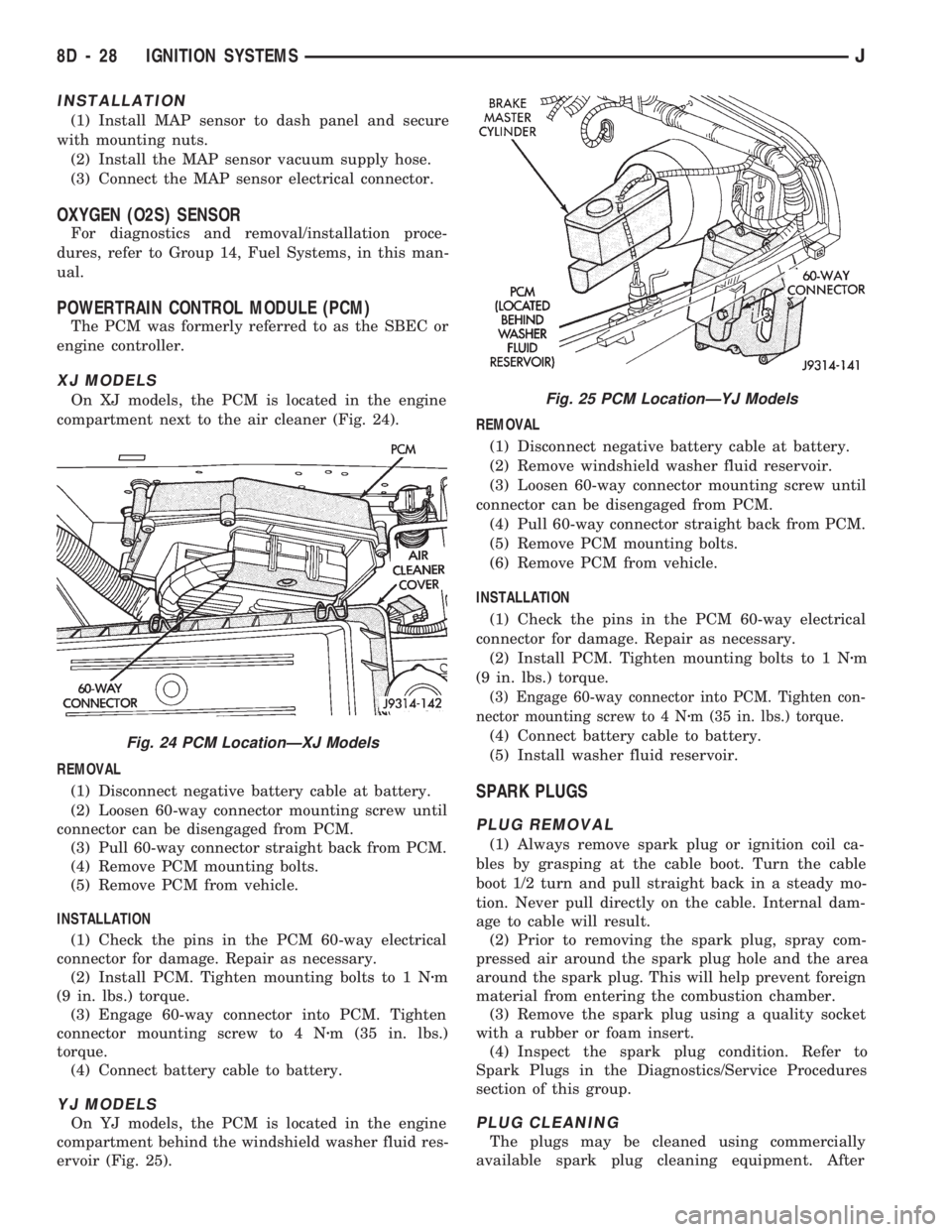
On XJ models, the PCM is located in the engine
compartment next to the air cleaner (Fig. 24).
REMOVAL
(1) Disconnect negative battery cable at battery.
(2) Loosen 60-way connector mounting screw until
connector can be disengaged from PCM.
(3) Pull 60-way connector straight back from PCM.
(4) Remove PCM mounting bolts.
(5) Remove PCM from vehicle.
INSTALLATION
(1) Check the pins in the PCM 60-way electrical
connector for damage. Repair as necessary.
(2) Install PCM. Tighten mounting bolts to 1 Nzm
(9 in. lbs.) torque.
(3) Engage 60-way connector into PCM. Tighten
connector mounting screw to 4 Nzm (35 in. lbs.)
torque.
(4) Connect battery cable to battery.
YJ MODELS
On YJ models, the PCM is located in the engine
compartment behind the windshield washer fluid res-
ervoir (Fig. 25).REMOVAL
(1) Disconnect negative battery cable at battery.
(2) Remove windshield washer fluid reservoir.
(3) Loosen 60-way connector mounting screw until
connector can be disengaged from PCM.
(4) Pull 60-way connector straight back from PCM.
(5) Remove PCM mounting bolts.
(6) Remove PCM from vehicle.
INSTALLATION
(1) Check the pins in the PCM 60-way electrical
connector for damage. Repair as necessary.
(2) Install PCM. Tighten mounting bolts to 1 Nzm
(9 in. lbs.) torque.
(3) Engage 60-way connector into PCM. Tighten con-
nector mounting screw to 4 Nzm (35 in. lbs.) torque.
(4) Connect battery cable to battery.
(5) Install washer fluid reservoir.
SPARK PLUGS
PLUG REMOVAL
(1) Always remove spark plug or ignition coil ca-
bles by grasping at the cable boot. Turn the cable
boot 1/2 turn and pull straight back in a steady mo-
tion. Never pull directly on the cable. Internal dam-
age to cable will result.
(2) Prior to removing the spark plug, spray com-
pressed air around the spark plug hole and the area
around the spark plug. This will help prevent foreign
material from entering the combustion chamber.
(3) Remove the spark plug using a quality socket
with a rubber or foam insert.
(4) Inspect the spark plug condition. Refer to
Spark Plugs in the Diagnostics/Service Procedures
section of this group.
PLUG CLEANING
The plugs may be cleaned using commercially
available spark plug cleaning equipment. After
Fig. 24 PCM LocationÐXJ Models
Fig. 25 PCM LocationÐYJ Models
8D - 28 IGNITION SYSTEMSJ