1994 JEEP CHEROKEE engine oil
[x] Cancel search: engine oilPage 118 of 1784

(4) Inspect ignition coil connections. Verify that
coil secondary cable is firmly connected to coil (Figs.
5or6).(5) Verify that distributor cap is correctly attached
to distributor. Be sure that spark plug cables are
firmly connected to the distributor cap and the spark
plugs in their correct firing order. Be sure that coil
cable is firmly connected to distributor cap and coil.
Be sure that camshaft position sensor wire connector
is firmly connected to harness connector (Figs. 7 or
8). Inspect spark plug condition. Refer to Group 8D,
Ignition System. Connect vehicle to an oscilloscope
and inspect spark events for fouled or damaged spark
plugs or cables.
(6) Verify that generator output wire, generator
connector and ground wire are firmly connected to
the generator (Fig. 9).
(7) Inspect the system ground connections at the
cylinder block behind the engine oil dipstick tube
(Fig. 10).
Fig. 4 PDCÐXJ Models
Fig. 5 Ignition CoilÐ2.5L Engine
Fig. 6 Ignition CoilÐ4.0L Engine
Fig. 7 Distributor and WiringÐ2.5L Engine
Fig. 8 Distributor and WiringÐ4.0L Engine
JFUEL SYSTEM 14 - 33
Page 133 of 1784

87 and 30. Continuity should not be present between
terminals number 87A and 30.
(8) Disconnect jumper wires from relay and 12
Volt power source.
If continuity or resistance tests did not pass, re-
place relay. If tests passed, refer to Group 8W, Wir-
ing Diagrams for additional circuit information. Also
refer to the appropriate Powertrain Diagnostic Proce-
dures manual for operation of the DRB scan tool.
STARTER MOTOR RELAY TEST
Refer to Group 8A, Battery/Starting/Charging/Sys-
tem Diagnostics, for starter motor relay testing.
INJECTOR TEST
Disconnect the injector wire connector from the in-
jector. Place an ohmmeter on the injector terminals.
Resistance reading should be approximately 14.5
ohms61.2 ohms at 20ÉC (68ÉF). Proceed to following
Injector Diagnosis chart.
FUEL SYSTEM PRESSURE TEST
Refer to the Fuel Delivery System section of this
group. See Fuel System Pressure Test.
ON-BOARD DIAGNOSTICS (OBD)
The Powertrain Control Module (PCM) has been
programmed to monitor many different circuits of the
fuel injection system. If a problem is sensed in a
monitored circuit often enough to indicate an actual
problem, a Diagnostic Trouble Code (DTC) is stored.
The DTC will be stored in the PCM memory for
eventual display to the service technician. If the
problem is repaired or ceases to exist, the PCM can-
cels the DTC after 51 engine starts.
Certain criteria must be met for a diagnostic trou-
ble code (DTC) to be entered into PCM memory. The
criteria may be a specific range of engine rpm, en-
gine temperature and/or input voltage to the PCM.
It is possible that a DTC for a monitored circuit
may not be entered into memory even though a mal-
function has occurred. This may happen because one
of the DTC criteria for the circuit has not been met.
Example: assume that one of the criteria for the
MAP sensor circuit is that the engine must be oper-
ating between 750 and 2000 rpm to be monitored for
a DTC. If the MAP sensor output circuit shorts to
ground when the engine rpm is above 2400 rpm, a 0
volt input will be seen by the PCM. A DTC will not
be entered into memory because the condition does
not occur within the specified rpm range.
A DTC indicates that the powertrain control mod-
ule (PCM) has recognized an abnormal signal in a
circuit or the system. A DTC may indicate the result
of a failure, but never identify the failed component
directly.There are several operating conditions that the
PCM does not monitor and set a DTC for. Refer to
the following Monitored Circuits and Non-Monitored
Circuits in this section.
MONITORED CIRCUITS
The powertrain control module (PCM) can detect
certain problems in the fuel injection system.
Open or Shorted Circuit- The PCM can deter-
mine if sensor output (which is the input to PCM) is
within proper range. It also determines if the circuit
is open or shorted.
Output Device Current Flow- The PCM senses
whether the output devices are hooked up.
If there is a problem with the circuit, the PCM
senses whether the circuit is open, shorted to ground
(-), or shorted to (+) voltage.
Oxygen Sensor- The PCM can determine if the
oxygen sensor is switching between rich and lean.
This is, once the system has entered Closed Loop. Re-
fer to Open Loop/Closed Loop Modes Of Operation in
the Component Description/System Operation section
for an explanation of Closed (or Open) Loop opera-
tion.
NON-MONITORED CIRCUITS
The PCM does not monitor the following circuits,
systems or conditions that could have malfunctions
that result in driveability problems. A Diagnostic
Trouble Code (DTC) may not be displayed for these
conditions.
Fuel Pressure: Fuel pressure is controlled by the
vacuum assisted fuel pressure regulator. The PCM
cannot detect a clogged fuel pump inlet filter, clogged
in-line fuel filter, or a pinched fuel supply or return
line. However, these could result in a rich or lean
condition causing an oxygen sensor DTC to be stored
in the PCM.
Secondary Ignition Circuit: The PCM cannot
detect an inoperative ignition coil, fouled or worn
spark plugs, ignition cross firing, or open circuited
spark plug cables.
Engine Timing: The PCM cannot detect an incor-
rectly indexed timing chain, camshaft sprocket or
crankshaft sprocket. The PCM also cannot detect an
incorrectly indexed distributor. However, these could
result in a rich or lean condition causing an oxygen
sensor DTC to be stored in the PCM.
Cylinder Compression: The PCM cannot detect
uneven, low, or high engine cylinder compression.
Exhaust System: The PCM cannot detect a
plugged, restricted or leaking exhaust system.
Fuel Injector Malfunctions: The PCM cannot de-
termine if the fuel injector is clogged, or the wrong
injector is installed. However, these could result in a
rich or lean condition causing an oxygen sensor DTC
to be stored in the PCM.
14 - 48 FUEL SYSTEMJ
Page 135 of 1784
Excessive Oil Consumption: Although the PCM
monitors exhaust stream oxygen content through ox-
ygen sensor (closed loop), it cannot determine exces-
sive oil consumption.
Throttle Body Air Flow: The PCM cannot detect
a clogged or restricted air cleaner inlet or air filter
element.
Evaporative System: The PCM will not detect a
restricted, plugged or loaded EVAP canister.
Vacuum Assist: Leaks or restrictions in the vac-
uum circuits of vacuum assisted engine control sys-
tem devices are not monitored by the PCM. However,
a vacuum leak at the MAP sensor will be monitored
and a diagnostic trouble code (DTC) will be gener-
ated by the PCM.
Powertrain Control Module (PCM) System
Ground: The PCM cannot determine a poor system
ground. However, a DTC may be generated as a re-
sult of this condition.
Powertrain Control Module (PCM) Connector
Engagement: The PCM cannot determine spread or
damaged connector pins. However, a DTC may be
generated as a result of this condition.
HIGH AND LOW LIMITS
The powertrain control module (PCM) compares in-
put signal voltages from each input device. It will es-
tablish high and low limits that are programmed into
it for that device. If the input voltage is not within
specifications and other Diagnostic Trouble Code
(DTC) criteria are met, a DTC will be stored in mem-
ory. Other DTC criteria might include engine rpm
limits or input voltages from other sensors or
switches. The other inputs might have to be sensed
by the PCM when it senses a high or low input volt-
age from the control system device in question.
ACCESSING DIAGNOSTIC TROUBLE CODES
A stored Diagnostic Trouble Code (DTC) can be dis-
played by cycling the ignition key On-Off-On-Off-On
within three seconds and observing the Malfunction
Indicator Lamp. This lamp was formerly referred to
as the Check Engine Lamp. The lamp is located on
the instrument panel.
They can also be displayed through the use of the
Diagnostic Readout Box (DRB) scan tool. The DRB
scan tool connects to the data link connector in the
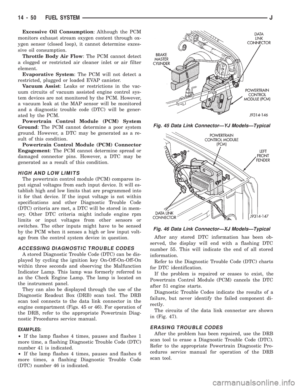
engine compartment (Figs. 45 or 46). For operation of
the DRB, refer to the appropriate Powertrain Diag-
nostic Procedures service manual.
EXAMPLES:
²If the lamp flashes 4 times, pauses and flashes 1
more time, a flashing Diagnostic Trouble Code (DTC)
number 41 is indicated.
²If the lamp flashes 4 times, pauses and flashes 6
more times, a flashing Diagnostic Trouble Code
(DTC) number 46 is indicated.After any stored DTC information has been ob-
served, the display will end with a flashing DTC
number 55. This will indicate the end of all stored
information.
Refer to the Diagnostic Trouble Code (DTC) charts
for DTC identification.
If the problem is repaired or ceases to exist, the
Powertrain Control Module (PCM) cancels the DTC
after 51 engine starts.
Diagnostic Trouble Codes indicate the results of a
failure, but never identify the failed component di-
rectly.
The circuits of the data link connector are shown
in (Fig. 47).
ERASING TROUBLE CODES
After the problem has been repaired, use the DRB
scan tool to erase a Diagnostic Trouble Code (DTC).
Refer to the appropriate Powertrain Diagnostic Pro-
cedures service manual for operation of the DRB
scan tool.
Fig. 45 Data Link ConnectorÐYJ ModelsÐTypical
Fig. 46 Data Link ConnectorÐXJ ModelsÐTypical
14 - 50 FUEL SYSTEMJ
Page 139 of 1784
MULTI-PORT FUEL INJECTION (MFI)ÐCOMPONENT REMOVAL/INSTALLATION
INDEX
page page
Accelerator Pedal and Throttle Cable......... 54
Air Cleaner Housing...................... 54
Air Conditioning (A/C) Clutch Relay........... 54
Air Filter............................... 54
Automatic Shut Down (ASD) Relay........... 54
Brake Switch............................ 54
Camshaft Position Sensor.................. 54
Crankshaft Position Sensor................. 55
Engine Coolant Temperature Sensor.......... 55
Fuel Filter.............................. 55
Fuel Injector............................ 55
Fuel Pump Module....................... 56
Fuel Pump Relay........................ 56
Fuel Rail Assembly....................... 56
Fuel System Pressure Release Procedure...... 56
Fuel Tank Pressure Relief/Rollover Valve...... 56
Fuel Tanks............................. 56Fuel Tubes/Lines/Hoses and Clamps.......... 56
Idle Air Control (IAC) Motor................. 56
Ignition Coil............................. 57
Intake Air Temperature Sensor.............. 54
Intake Manifold.......................... 57
Manifold Absolute Pressure (MAP) Sensor..... 57
Oxygen (O2S) Sensor..................... 57
Park Neutral Switch....................... 58
Power Steering Pressure SwitchÐ2.5L
Engine Only........................... 58
Powertrain Control Module (PCM)............ 58
Quick-Connect Fittings..................... 59
Throttle Body............................ 59
Throttle Position Sensor (TPS).............. 59
Torque Converter Clutch Relay.............. 60
Vehicle Speed Sensor..................... 60
ACCELERATOR PEDAL AND THROTTLE CABLE
Refer to the Accelerator Pedal and Throttle Cable
section of this group for removal/installation proce-
dures.
AIR CONDITIONING (A/C) CLUTCH RELAY
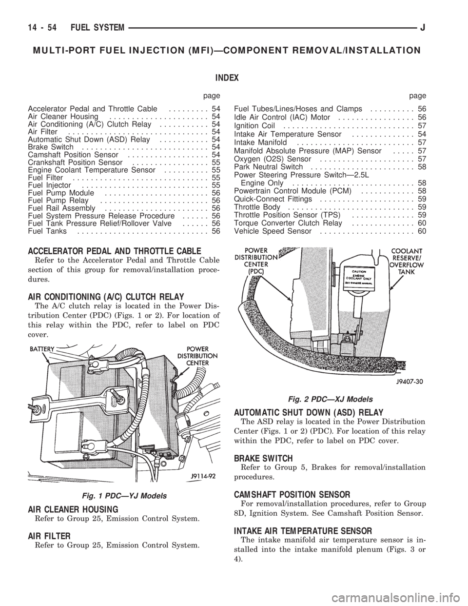
The A/C clutch relay is located in the Power Dis-
tribution Center (PDC) (Figs. 1 or 2). For location of
this relay within the PDC, refer to label on PDC
cover.
AIR CLEANER HOUSING
Refer to Group 25, Emission Control System.
AIR FILTER
Refer to Group 25, Emission Control System.
AUTOMATIC SHUT DOWN (ASD) RELAY
The ASD relay is located in the Power Distribution
Center (Figs. 1 or 2) (PDC). For location of this relay
within the PDC, refer to label on PDC cover.
BRAKE SWITCH
Refer to Group 5, Brakes for removal/installation
procedures.
CAMSHAFT POSITION SENSOR
For removal/installation procedures, refer to Group
8D, Ignition System. See Camshaft Position Sensor.
INTAKE AIR TEMPERATURE SENSOR
The intake manifold air temperature sensor is in-
stalled into the intake manifold plenum (Figs. 3 or
4).
Fig. 1 PDCÐYJ Models
Fig. 2 PDCÐXJ Models
14 - 54 FUEL SYSTEMJ
Page 142 of 1784
REMOVAL
(1) Disconnect the electrical connector from the
IAC motor.
(2) Remove IAC motor torx head mounting bolts.
(3) Remove IAC motor.
INSTALLATION
(1) Install IAC motor into throttle body and
tighten retaining bolts.
(2) Connect electrical connector to IAC motor.
IGNITION COIL
Refer to Group 8D, Ignition Systems for removal/
installation procedures.
INTAKE MANIFOLD
Refer to Group 11, Exhaust System and Intake
Manifold for removal/installation procedures.
MANIFOLD ABSOLUTE PRESSURE (MAP) SENSOR
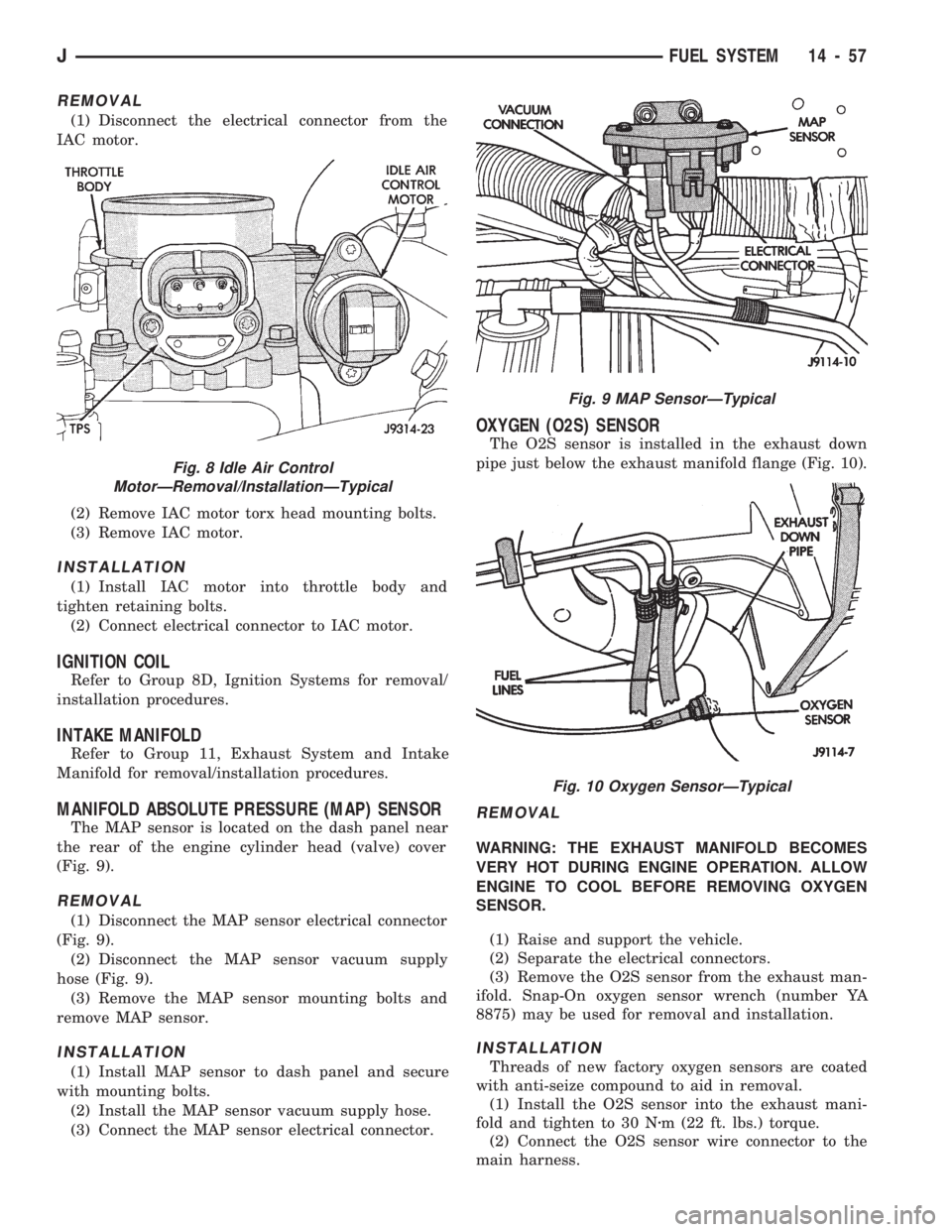
The MAP sensor is located on the dash panel near
the rear of the engine cylinder head (valve) cover
(Fig. 9).
REMOVAL
(1) Disconnect the MAP sensor electrical connector
(Fig. 9).
(2) Disconnect the MAP sensor vacuum supply
hose (Fig. 9).
(3) Remove the MAP sensor mounting bolts and
remove MAP sensor.
INSTALLATION
(1) Install MAP sensor to dash panel and secure
with mounting bolts.
(2) Install the MAP sensor vacuum supply hose.
(3) Connect the MAP sensor electrical connector.
OXYGEN (O2S) SENSOR
The O2S sensor is installed in the exhaust down
pipe just below the exhaust manifold flange (Fig. 10).
REMOVAL
WARNING: THE EXHAUST MANIFOLD BECOMES
VERY HOT DURING ENGINE OPERATION. ALLOW
ENGINE TO COOL BEFORE REMOVING OXYGEN
SENSOR.
(1) Raise and support the vehicle.
(2) Separate the electrical connectors.
(3) Remove the O2S sensor from the exhaust man-
ifold. Snap-On oxygen sensor wrench (number YA
8875) may be used for removal and installation.
INSTALLATION
Threads of new factory oxygen sensors are coated
with anti-seize compound to aid in removal.
(1) Install the O2S sensor into the exhaust mani-
fold and tighten to 30 Nzm (22 ft. lbs.) torque.
(2) Connect the O2S sensor wire connector to the
main harness.
Fig. 8 Idle Air Control
MotorÐRemoval/InstallationÐTypical
Fig. 9 MAP SensorÐTypical
Fig. 10 Oxygen SensorÐTypical
JFUEL SYSTEM 14 - 57
Page 157 of 1784

when the cover is off. The second involves adding to,
or filling the cylinder reservoirs with a non-recom-
mended fluid.
Brake fluid contaminated with only dirt, or debris
usually retains a normal appearance. In some cases,
the foreign material will remain suspended in the
fluid and be visible. The fluid and foreign material
can be removed from the reservoir with a suction
gun but only if the brakes have not been applied. If
the brakes are applied after contamination, system
flushing will be required. The master cylinder may
also have to be disassembled, cleaned and the piston
seals replaced. Foreign material lodged in the reser-
voir compensator/return ports can cause brake drag
by restricting fluid return after brake application.
Brake fluid contaminated by a non-recommended
fluid will usually be discolored, milky, oily looking,
or foamy. In some cases, it may even appear as if the
fluid contains sludge.However, remember that
brake fluid will darken in time and occasionally
be cloudy in appearance. These are normal con-
ditions and should not be mistaken for contami-
nation.
If some type of oil has been added to the system,
the fluid will separate into distinct layers. To verify
this, drain off a sample with a clean suction gun.
Then pour the sample into a glass container and ob-
serve fluid action. If the fluid separates into distinct
layers, it is definitely contaminated.
The only real correction for contamination by non-
recommended fluid is to flush the entire hydraulic
system and replace all the seals.
BRAKE NOISE
Squeak/Squeal
Brake squeak or squeal may be due to linings that
are wet or contaminated with brake fluid, grease, or
oil. Glazed linings and rotors with hard spots can
also contribute to squeak. Dirt and foreign material
embedded in the brake lining will also cause squeak/
squeal.
A very loud squeak or squeal is frequently a sign
of severely worn brake lining. If the lining has worn
through to the brakeshoes in spots, metal-to-metal
contact occurs. If the condition is allowed to continue,
rotors can become so scored that replacement is nec-
essary.
Thump/Clunk
Thumping or clunk noises during braking are fre-
quentlynotcaused by brake components. In many
cases, such noises are caused by loose or damaged
steering, suspension, or engine components. How-
ever, calipers that bind on the slide surfaces can gen-
erate a thump or clunk noise. In addition, worn out,
improperly adjusted, or improperly assembled rear
brakeshoes can also produce a thump noise.Chatter/Shudder
Brake chatter, or shudder is usually caused by
loose or worn components, or glazed/burnt lining. Ro-
tors with hard spots can also contribute to chatter.
Additional causes of chatter are out of tolerance ro-
tors, brake lining not securely attached to the shoes,
loose wheel bearings and contaminated brake lining.
BRAKELINING CONTAMINATION
Brakelining contamination is usually a product of
leaking calipers or wheel cylinders, driving through
deep water puddles, or lining that has become cov-
ered with grease and grit during repair.
WHEEL AND TIRE PROBLEMS
Some conditions attributed to brake components
may actually be caused by a wheel or tire problem.
A damaged wheel can cause shudder, vibration and
pull. A worn or damaged tire can also cause pull.
Severely worn tires with very little tread left can
produce a condition similar to grab as the tire loses
and recovers traction.
Flat-spotted tires can cause vibration and wheel
tramp and generate shudder during brake operation.
A tire with internal damage such as a severe
bruise or ply separation can cause pull and vibration.
DIAGNOSING PARKING BRAKE PROBLEMS
Adjustment Mechanism
Parking brake adjustment is controlled by a
cable tensioner mechanism. This applies to 1991
through 1994 YJ models and 1992 and later XJ
models. The cable tensioner, once adjusted at
the factory, will not need further adjustment un-
der normal circumstances. There are only two
instances when adjustment is required. The first
is when a new tensioner, or cables have been in-
stalled. And the second, is when the tensioner
and cables are disconnected for access to other
brake components.
Parking Brake problem Causes
In most cases, the actual cause of an improperly
functioning parking brake (too loose/too tight/wont
hold), can be traced to a drum brake component.
The leading cause of improper parking brake
operation, is excessive clearance between the
brakeshoes and the drum surface. Excessive
clearance is a result of: lining and/or drum wear;
oversize drums; or inoperative shoe adjuster
components.
Excessive parking brake lever travel (sometimes
described as a loose lever or too loose condition), is
the result of worn brakeshoes/drums, improper
brakeshoe adjustment, or mis-assembled brake parts.
A ``too loose'' condition can also be caused by inop-
erative brakeshoe adjusters. If the adjusters are mis-
5 - 10 BRAKESJ
Page 234 of 1784
COOLING SYSTEM
CONTENTS
page page
DIAGNOSIS............................. 4
ENGINE ACCESSORY DRIVE BELTS........ 31
ENGINE BLOCK HEATER................. 37GENERAL INFORMATION.................. 1
SERVICE PROCEDURES................... 9
SPECIFICATIONS....................... 38
GENERAL INFORMATION
Throughout this group, references are made to par-
ticular vehicle models by alphabetical designation
(XJ or YJ) or by the particular vehicle nameplate. A
chart showing a breakdown of alphabetical designa-
tions is included in the Introduction section at the
beginning of this manual.
COOLING SYSTEM
The cooling system regulates engine operating tem-
perature. It allows the engine to reach normal oper-
ating temperature as quickly as possible, maintains
normal operating temperature and prevents over-
heating.
The cooling system also provides a means of heat-
ing the passenger compartment and cooling the auto-
matic transmission fluid (if equipped). The cooling
system is pressurized and uses a centrifugal water
pump to circulate coolant throughout the system.
An optional factory installed heavy duty cooling
package is available on most models. The package
consists of a radiator that has an increased numberof cooling fins. XJ models equipped with a 4.0L 6 cyl-
inder engine and heavy duty cooling and/or air con-
ditioning also have an auxiliary electric cooling fan.
COOLING SYSTEM COMPONENTS
The cooling system consists of:
²A radiator
²Cooling fan (mechanical and/or electrical)
²Thermal viscous fan drive
²Fan shroud
²Radiator pressure cap
²Thermostat
²Coolant reserve/overflow system
²Transmission oil cooler (if equipped with an auto-
matic transmission)
²Coolant
²Water pump
²Hoses and hose clamps
SYSTEM COOLANT ROUTING
For cooling system flow routings, refer to Figs. 1, 2,
3or4.
JCOOLING SYSTEM 7 - 1
Page 242 of 1784
SERVICE PROCEDURES
INDEX
page page
Coolant................................ 15
Coolant Reserve/Overflow System............ 19
Cooling System Cleaning/Reverse Flushing..... 17
Cooling System Fans..................... 26
Cooling System Hoses.................... 26
Draining Cooling System................... 16
Radiator Pressure Cap.................... 20
Radiators............................... 22Refilling Cooling System................... 17
Testing Cooling System for Leaks............ 18
Thermostat............................. 13
Transmission Oil Coolers................... 29
Water Pump Tests........................ 9
Water PumpsÐGeneral Information............ 9
Water PumpsÐRemoval/Installation........... 10
WATER PUMPSÐGENERAL INFORMATION
A centrifugal water pump circulates coolant
through the water jackets, passages, intake manifold,
radiator core, cooling system hoses and heater core.
The pump is driven from the engine crankshaft by a
drive belt on all engines.
The water pump impeller is pressed onto the rear
of a shaft that rotates in bearings pressed into the
housing. The housing has a small hole to allow seep-
age to escape. The water pump seals are lubricated
by the antifreeze in the coolant mixture. No addi-
tional lubrication is necessary.
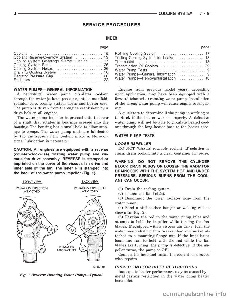
CAUTION: All engines are equipped with a reverse
(counter-clockwise) rotating water pump and vis-
cous fan drive assembly. REVERSE is stamped or
imprinted on the cover of the viscous fan drive and
inner side of the fan. The letter R is stamped into
the back of the water pump impeller (Fig. 1).Engines from previous model years, depending
upon application, may have been equipped with a
forward (clockwise) rotating water pump. Installation
of the wrong water pump will cause engine overheat-
ing.
A quick test to determine if the pump is working is
to check if the heater warms properly. A defective
water pump will not be able to circulate heated cool-
ant through the long heater hose to the heater core.
WATER PUMP TESTS
LOOSE IMPELLER
DO NOT WASTE reusable coolant. If solution is
clean, drain coolant into a clean container for reuse.
WARNING: DO NOT REMOVE THE CYLINDER
BLOCK DRAIN PLUGS OR LOOSEN THE RADIATOR
DRAINCOCK WITH THE SYSTEM HOT AND UNDER
PRESSURE. SERIOUS BURNS FROM THE COOL-
ANT CAN OCCUR.
(1) Drain the cooling system.
(2) Loosen the fan belt(s).
(3) Disconnect the lower radiator hose from the
water pump.
(4) Bend a stiff clothes hanger or welding rod as
shown in (Fig. 2).
(5) Position the rod in the water pump inlet and
attempt to hold the impeller while turning the fan
blades. If equipped with a viscous fan drive, turn the
water pump shaft with a breaker bar and socket at-
tached to a mounting flange nut. If the impeller is
loose and can be held with the rod while the fan
blades are turning, the pump is defective. If the im-
peller turns, the pump is OK.
Connect the hose and install the coolant, or proceed
with repairs.
INSPECTING FOR INLET RESTRICTIONS
Inadequate heater performance may be caused by a
metal casting restriction in the water pump heater
hose inlet.Fig. 1 Reverse Rotating Water PumpÐTypical
JCOOLING SYSTEM 7 - 9