1994 JEEP CHEROKEE engine oil
[x] Cancel search: engine oilPage 247 of 1784
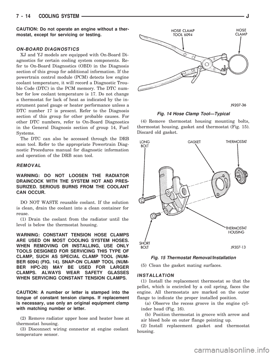
CAUTION: Do not operate an engine without a ther-
mostat, except for servicing or testing.
ON-BOARD DIAGNOSTICS
XJ and YJ models are equipped with On-Board Di-
agnostics for certain cooling system components. Re-
fer to On-Board Diagnostics (OBD) in the Diagnosis
section of this group for additional information. If the
powertrain control module (PCM) detects low engine
coolant temperature, it will record a Diagnostic Trou-
ble Code (DTC) in the PCM memory. The DTC num-
ber for low coolant temperature is 17. Do not change
a thermostat for lack of heat as indicated by the in-
strument panel gauge or heater performance unless a
DTC number 17 is present. Refer to the Diagnosis
section of this group for other probable causes. For
other DTC numbers, refer to On-Board Diagnostics
in the General Diagnosis section of group 14, Fuel
Systems.
The DTC can also be accessed through the DRB
scan tool. Refer to the appropriate Powertrain Diag-
nostic Procedures manual for diagnostic information
and operation of the DRB scan tool.
REMOVAL
WARNING: DO NOT LOOSEN THE RADIATOR
DRAINCOCK WITH THE SYSTEM HOT AND PRES-
SURIZED. SERIOUS BURNS FROM THE COOLANT
CAN OCCUR.
DO NOT WASTE reusable coolant. If the solution
is clean, drain the coolant into a clean container for
reuse.
(1) Drain the coolant from the radiator until the
level is below the thermostat housing.
WARNING: CONSTANT TENSION HOSE CLAMPS
ARE USED ON MOST COOLING SYSTEM HOSES.
WHEN REMOVING OR INSTALLING, USE ONLY
TOOLS DESIGNED FOR SERVICING THIS TYPE OF
CLAMP, SUCH AS SPECIAL CLAMP TOOL (NUM-
BER 6094) (FIG. 14). SNAP-ON CLAMP TOOL (NUM-
BER HPC-20) MAY BE USED FOR LARGER
CLAMPS. ALWAYS WEAR SAFETY GLASSES
WHEN SERVICING CONSTANT TENSION CLAMPS.
CAUTION: A number or letter is stamped into the
tongue of constant tension clamps. If replacement
is necessary, use only an original equipment clamp
with matching number or letter.
(2) Remove radiator upper hose and heater hose at
thermostat housing.
(3) Disconnect wiring connector at engine coolant
temperature sensor.(4) Remove thermostat housing mounting bolts,
thermostat housing, gasket and thermostat (Fig. 15).
Discard old gasket.
(5) Clean the gasket mating surfaces.
INSTALLATION
(1) Install the replacement thermostat so that the
pellet, which is encircled by a coil spring, faces the
engine. All thermostats are marked on the outer
flange to indicate the proper installed position.
(a) Observe the recess groove in the engine cyl-
inder head (Fig. 16).
(b) Position thermostat in groove with arrow and
air bleed hole on outer flange pointing up.
(2) Install replacement gasket and thermostat
housing.
Fig. 14 Hose Clamp ToolÐTypical
Fig. 15 Thermostat Removal/Installation
7 - 14 COOLING SYSTEMJ
Page 252 of 1784

Leakage Test. Do this if it is certain that coolant is
being lost and no leaks can be detected.
²Drops Slowly: Shows a small leak or seepage is oc-
curring. Examine all connections for seepage or
slight leakage with a flashlight. Inspect the radiator,
hoses, gasket edges and heater. Seal any small leak
holes with a Sealer Lubricant or equivalent. Repair
leak holes and reinspect the system with pressure
applied.
²Drops Quickly: Shows that a serious leakage is oc-
curring. Examine the system for serious external
leakage. If no leaks are visible, inspect for internal
leakage. Large radiator leak holes should be repaired
by a reputable radiator repair shop.
INTERNAL LEAKAGE INSPECTION
Remove the oil pan drain plug and drain a small
amount of engine oil. Coolant, being heavier will
drain first, or operate engine to churn oil, then ex-
amine dipstick for water globules. Inspect the trans-
mission dipstick for water globules. Inspect the
transmission fluid cooler for leakage. Operate the en-
gine without the pressure cap on the radiator until
thermostat opens.
Attach a Pressure Tester to the filler neck. If pres-
sure builds up quickly, a leak exists as result of a
faulty cylinder head gasket or crack in the engine.
Repair as necessary.
WARNING: DO NOT ALLOW PRESSURE TO EX-
CEED 124 KPA (18 PSI). TURN THE ENGINE OFF.
TO RELEASE THE PRESSURE, ROCK THE TESTER
FROM SIDE TO SIDE. WHEN REMOVING THE
TESTER, DO NOT TURN THE TESTER MORE THAN
1/2 TURN IF THE SYSTEM IS UNDER PRESSURE.
If there is no immediate pressure increase, pump
the Pressure Tester until the indicated pressure is
within the system range. Vibration of the gauge
pointer indicates compression or combustion leakage
into the cooling system.WARNING: DO NOT DISCONNECT THE SPARK
PLUG WIRES WHILE THE ENGINE IS OPERATING.
CAUTION: Do not operate the engine with a spark
plug shorted for more than a minute. The catalytic
converter may be damaged.
Isolate the compression leak by shorting each
spark plug to the cylinder block. The gauge pointer
should stop or decrease vibration when spark plug
for leaking cylinder is shorted. This happens because
of the absence of combustion pressure.
COMBUSTION LEAKAGE TEST (WITHOUT
PRESSURE TESTER)
DO NOT WASTE reusable coolant. If the solution
is clean, drain the coolant into a clean container for
reuse.
WARNING: DO NOT REMOVE THE CYLINDER
BLOCK DRAIN PLUGS OR LOOSEN THE RADIATOR
DRAINCOCK WITH THE SYSTEM HOT AND UNDER
PRESSURE. SERIOUS BURNS FROM COOLANT
CAN OCCUR.
Drain sufficient coolant to allow for thermostat re-
moval. Refer to Thermostat Replacement. Disconnect
the water pump drive belt.
Disconnect the upper radiator hose from the ther-
mostat housing. Remove the housing and thermostat.
Install the thermostat housing.
Add coolant to the radiator to bring the level to
within 6.3 mm (1/4 in) of the top of the thermostat
housing.
CAUTION: Avoid overheating. Do not operate the
engine for an excessive period of time. Open the
draincock immediately after the test to eliminate
boil over of coolant.
Start the engine and accelerate rapidly three times
(to approximately 3000 rpm) while observing the
coolant. If internal engine combustion gases are leak-
ing into the cooling system, bubbles will appear in
the coolant. If bubbles do not appear, there is no in-
ternal combustion gas leakage.
COOLANT RESERVE/OVERFLOW SYSTEM
The system works along with the radiator pressure
cap. This is done by using thermal expansion and
contraction of the coolant to keep the coolant free of
trapped air. It provides:
²A volume for coolant expansion and contraction.
²A convenient and safe method for checking/adjust-
ing coolant level at atmospheric pressure. This is
done without removing the radiator pressure cap.
²Some reserve coolant to cover minor leaks and
evaporation or boiling losses.
Fig. 20 Pressurizing SystemÐTypical
JCOOLING SYSTEM 7 - 19
Page 260 of 1784
speed of the fan to a predetermined maximum level
at higher engine speeds. A bimetallic spring coil is
located on the front face. This spring coil reacts to
the temperature of the radiator discharge air. It en-
gages the viscous fan drive for higher fan speed if
the air temperature from the radiator rises above a
certain point. Until additional engine cooling is nec-
essary, the fan will remain at a reduced rpm regard-
less of engine speed.
Only when sufficient heat is present, will the vis-
cous fan drive engage. This is when the air flowing
through the radiator core causes a reaction from the
bimetallic coil. It then increases fan speed to provide
the necessary additional engine cooling.
Once the engine has cooled, the radiator discharge
temperature will drop. The bimetallic coil again re-
acts and the fan speed is reduced to the previous dis-
engaged speed.
CAUTION: Engines equipped with serpentine drive
belts have reverse rotating fans and viscous fan
drives. They are marked with the word REVERSE to
designate their usage. Installation of the wrong fan
or viscous fan drive can result in engine overheat-
ing.
VISCOUS FAN DRIVE TEST
The cooling system must be in good condition. This
is checked prior to performing the following test. It
also will ensure against excessively high coolant
temperature.
CAUTION: Be sure that there is adequate fan blade
clearance before drilling.(1) Drill a 3.18-mm (1/8-in) diameter hole in the
top center of the fan shroud.
(2) Obtain a dial thermometer with an 8 inch stem
(or equivalent). It should have a range of -18É-to-
105ÉC (0É-to-220É F). Insert thermometer through the
hole in the shroud. Be sure that there is adequate
clearance from the fan blades.
(3) Connect a tachometer and an engine ignition
timing light (timing light is to be used as a strobe
light).
(4) Block the air flow through the radiator. Secure
a sheet of plastic in front of the radiator (or air con-
ditioner condenser). Use tape at the top to secure the
plastic and be sure that the air flow is blocked.
(5) Be sure that the air conditioner (if equipped) is
turned off.
WARNING: USE EXTREME CAUTION WHEN THE
ENGINE IS OPERATING. DO NOT STAND IN A DI-
RECT LINE WITH THE FAN. DO NOT PUT YOUR
HANDS NEAR THE PULLEYS, BELTS OR FAN. DO
NOT WEAR LOOSE CLOTHING.
(6) Start the engine and operate at 2400 rpm with
the timing light (strobe light) aimed at the fan
blades. Within ten minutes the air temperature (in-
dicated on the dial thermometer) should be 88É C
(190É F). Satisfactory operation of the fan drive re-
quires that it engage before or at 88É C (190É F). En-
gagement is distinguishable by a definite increase in
flow noise. The timing light also will indicate an in-
crease in the speed of the fan.
(7) When the air temperature reaches 88É C (190É
F), remove the plastic sheet. Satisfactory operation of
the viscous fan requires the air temperature to drop
20É F (11É C) or more. A definite decrease of audible-
fan-air-flow-noise should be noticed. Replace defec-
tive fan assemblies.
VISCOUS FAN DRIVE REPLACEMENT
REMOVAL
Some engines have the mechanical fan/viscous fan
drive assembly mounted directly to the water pump
hub (Fig. 38). It may also be mounted to a hub/bear-
ing attached to an aluminum bracket on the right
front side of engine (Fig. 39).
(1) Loosen but do not remove at this time, the four
fan hub mounting nuts (Figs. 38 or 39).
(2) Remove accessory serpentine drive belt. Refer
to Belt Service in the Engine Accessory Drive Belt
section of this group.
(3) Some models with certain engines may require
the removal of the fan shroud to remove the viscous
fan drive. The fan shroud and fan blade/viscous fan
drive should be removed from the vehicle as one as-
sembly.
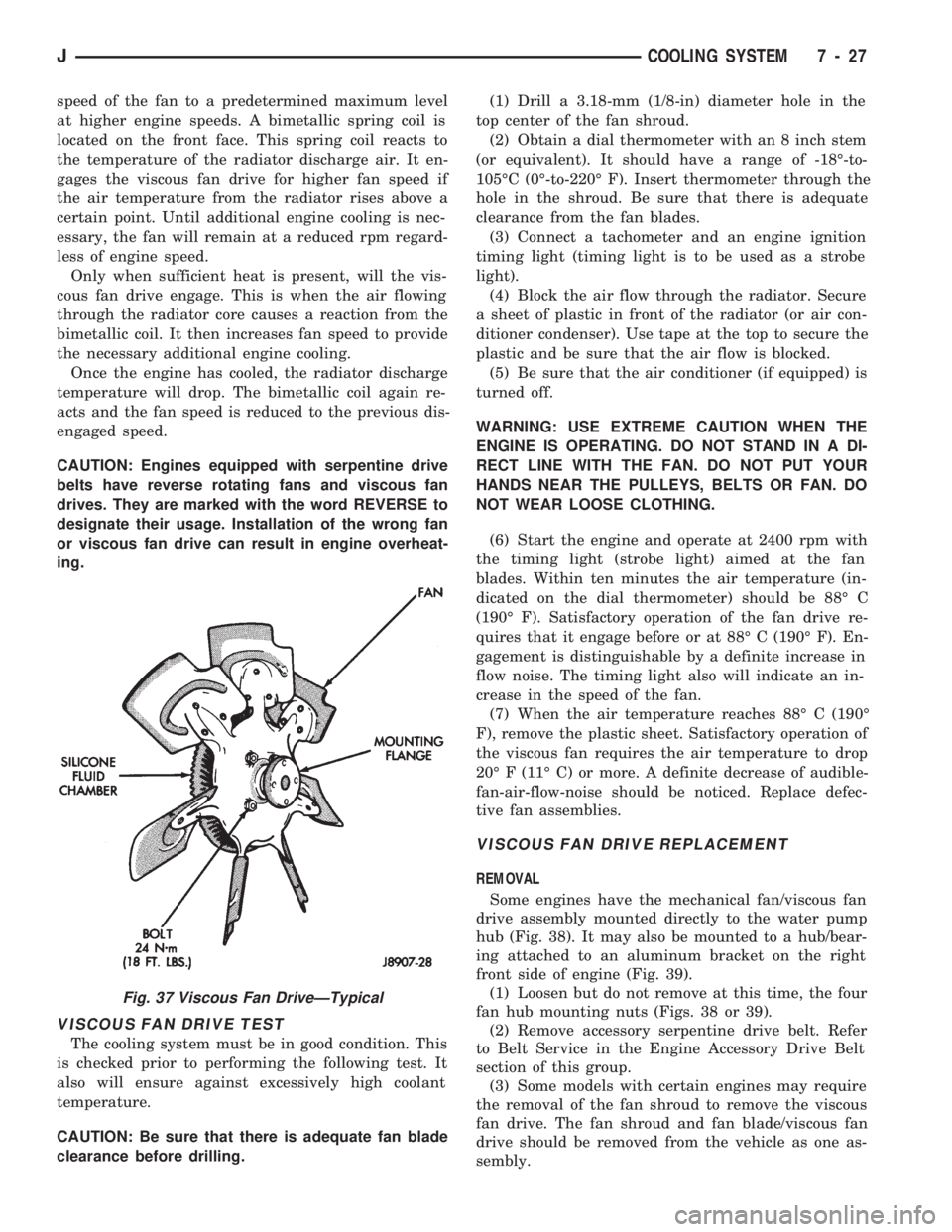
Fig. 37 Viscous Fan DriveÐTypical
JCOOLING SYSTEM 7 - 27
Page 262 of 1784
through the relay. When coolant temperature is be-
low 88ÉC (190ÉF), the PCM opens the ground path to
the relay. This will prevent the cooling fan from be-
ing energized.
Whenever the air conditioning is used, the PCM
engages the auxiliary cooling fan. It provides a
ground path to the cooling fan relay.
DIAGNOSIS
The powertrain control module (PCM) will enter a
diagnostic trouble code (DTC) number 35 in memory
if it detects a problem in the auxiliary cooling fan re-
lay or circuit. This will be read as a flashing signal
at the instrument panel mounted Malfunction Indica-
tor Lamp (formerly referred to as the Check Engine
Lamp). Refer to On-Board Diagnostics in Group 14,
Fuel Systems for information on accessing a DTC.
The DTC can also be accessed through the DRB
scan tool. Refer to the appropriate Powertrain Diag-
nostic Procedures manual for diagnostic information
and operation of the DRB scan tool.
REMOVAL
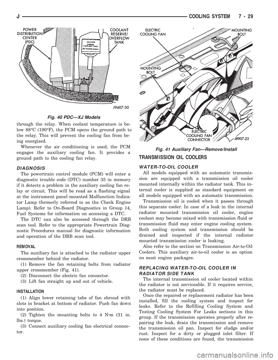
The auxiliary fan is attached to the radiator upper
crossmember behind the radiator.
(1) Remove the fan retaining bolts from radiator
upper crossmember (Fig. 41).
(2) Disconnect the electric fan connector.
(3) Lift fan straight up and out of vehicle.
INSTALLATION
(1) Align lower retaining tabs of fan shroud with
slots in bracket at bottom of radiator. Push fan down
into position.
(2) Tighten the mounting bolts to 4 Nzm (31 in.
lbs.) torque.
(3) Connect auxiliary cooling fan electrical connec-
tor.
TRANSMISSION OIL COOLERS
WATER-TO-OIL COOLER
All models equipped with an automatic transmis-
sion are equipped with a transmission oil cooler
mounted internally within the radiator tank. This in-
ternal cooler is supplied as standard equipment on
all models equipped with an automatic transmission.
Transmission oil is cooled when it passes through
this separate cooler. In case of a leak in the internal
radiator mounted transmission oil cooler, engine
coolant may become mixed with transmission fluid or
transmission fluid may enter engine cooling system.
Both cooling system and transmission should be
drained and inspected if the internal radiator
mounted transmission cooler is leaking.
Also refer to the section on Transmission Air-to-Oil
Coolers. This auxiliary air-to-oil cooler is an option
on most engine packages.
REPLACING WATER-TO-OIL COOLER IN
RADIATOR SIDE TANK
The internal transmission oil cooler located within
the radiator is not serviceable. If it requires service,
the radiator must be replaced.
Once the repaired or replacement radiator has been
installed, fill the cooling system and inspect for
leaks. Refer to the Refilling Cooling System and
Testing Cooling System For Leaks sections in this
group. If the transmission operates properly after re-
pairing the leak, drain the transmission and remove
the transmission oil pan. Inspect for sludge and/or
rust. Inspect for a dirty or plugged inlet filter. If
none of these conditions are found, the transmission
Fig. 40 PDCÐXJ Models
Fig. 41 Auxiliary FanÐRemove/Install
JCOOLING SYSTEM 7 - 29
Page 263 of 1784
and torque convertor may not require reconditioning.
Refer to Group 21 for automatic transmission servic-
ing.
AIR-TO-OIL COOLER
An auxiliary air-to-oil transmission oil cooler is
available with most engine packages.
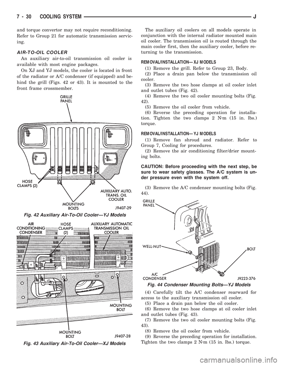
On XJ and YJ models, the cooler is located in front
of the radiator or A/C condenser (if equipped) and be-
hind the grill (Figs. 42 or 43). It is mounted to the
front frame crossmember.The auxiliary oil coolers on all models operate in
conjunction with the internal radiator mounted main
oil cooler. The transmission oil is routed through the
main cooler first, then the auxiliary cooler, before re-
turning to the transmission.
REMOVAL/INSTALLATIONÐXJ MODELS
(1) Remove the grill. Refer to Group 23, Body.
(2) Place a drain pan below the transmission oil
cooler.
(3) Remove the two hose clamps at oil cooler inlet
and outlet tubes (Fig. 42).
(4) Remove the two oil cooler mounting bolts (Fig.
42).
(5) Remove the oil cooler from vehicle.
(6) Reverse the preceding operation for installa-
tion. Tighten the two clamps 2 Nzm (15 in. lbs.)
torque.
REMOVAL/INSTALLATIONÐYJ MODELS
(1) Remove fan shroud and radiator. Refer to
Group 7, Cooling for procedures.
(2) Remove the air conditioning filter/drier mount-
ing bolts.
CAUTION: Before proceeding with the next step, be
sure to wear safety glasses. The A/C system is un-
der pressure even with the system off.
(3) Remove the A/C condenser mounting bolts (Fig.
44).
(4) Carefully tilt the A/C condenser rearward for
access to the auxiliary transmission oil cooler.
(5) Place a drain pan below the oil cooler.
(6) Remove the two hose clamps at oil cooler inlet
and outlet tubes (Fig. 43).
(7) Remove the two oil cooler mounting bolts (Fig.
43).
(8) Remove the oil cooler from vehicle.
(9) Reverse the preceding operation for installation.
Tighten the two clamps 2 Nzm (15 in. lbs.) torque.
Fig. 42 Auxiliary Air-To-Oil CoolerÐYJ Models
Fig. 43 Auxiliary Air-To-Oil CoolerÐXJ Models
Fig. 44 Condenser Mounting BoltsÐYJ Models
7 - 30 COOLING SYSTEMJ
Page 282 of 1784
ENGINE STARTER MOTOR TEST PROCEDURES ON VEHICLE
INDEX
page page
2.5L Starter Motor Noise Diagnosis........... 13
General Information........................ 9
Starter Control Circuit Tests................ 11
Starter Feed Circuit Tests - (Voltage Drop Method).9
Starter System Diagnostic Inspections.......... 9
Starting System Cold Cranking Test........... 9
GENERAL INFORMATION
The starting system consists of an:
²ignition switch
²starter relay
²park/neutral position switch (automatic transmis-
sion)
²wiring harness
²battery
²starter motor with an integral solenoid.
These components form 2 separate circuits. A high
amperage circuit that feeds the starter motor up to
300+ amps, and a control circuit that operates on
less than 20 amps.
STARTER SYSTEM DIAGNOSTIC INSPECTIONS
Before removing any unit from the starter motor
system for repair, perform the following inspections:
BATTERY INSPECTION
To determine condition of the battery, perform the
testing procedure outlined in Battery Test Proce-
dures.
WIRING INSPECTION
Inspect wiring for damage. Inspect all connections
at the starter motor solenoid, park/neutral position
switch (if equipped), back-up lamp switch connector,
ignition switch, starter relay, and battery (including
all ground connections). Clean and tighten all con-
nections as required.
SOLENOID, RELAY AND IGNITION SWITCH
INSPECTION
Inspect the solenoid, relay and switch to determine
their condition. Also, if equipped with automatic
transmission, inspect condition of the park/neutral
position switch. Testing information can be found in
the following pages.
STARTING SYSTEM COLD CRANKING TEST
(1) Battery must first pass load and voltage drop
tests and be fully charged before proceeding. Refer to
Battery Test Procedures.(2) Connect a suitable volt-ampere tester to the
battery terminals (Fig. 1). Refer to the operating in-
structions provided with the tester being used.
(3) Fully engage parking brake, place manual
transmission in NEUTRAL, automatic transmission
in PARK.
(4) Verify that all lamps and accessories are OFF.
(5) Remove coil secondary cable from distributor
and connect to ground.
(6) Rotate and hold the ignition switch in the
START position. Note cranking voltage and amper-
age.
(a) If voltage reads above 9.6 volts and amperage
draw reads above specifications, go to Starter Feed
Circuit Tests.
(b) If voltage reads 12.5 volts or greater and am-
perage reads below specifications, go to Starter
Control Circuit Tests.
A cold engine will increase starter motor cur-
rent and reduce battery voltage.
STARTER FEED CIRCUIT TESTS - (VOLTAGE DROP
METHOD)
The voltage drop tests will determine if there is ex-
cessive resistance in the high current circuit. When
performing these tests, it is important that the volt-
meter be connected to the terminals that the cables
are connected to, instead of to the cables themselves.
For example, when testing between the battery and
solenoid, touch the voltmeter test probes to the bat-
tery post and the solenoid threaded stud. The follow-
ing operation will require a voltmeter, accurate to
1/10 of a volt.
Before performing the tests, assure the following
procedures are accomplished:
²remove coil secondary cable from distributor and
connect to ground
²transmission in NEUTRAL (manual transmission)
or PARK (automatic transmission)
²parking brake applied
²battery is fully charged (refer to Battery Test Pro-
cedures).
JBATTERY/STARTING/CHARGING SYSTEMS DIAGNOSTICS 8A - 9
Page 284 of 1784
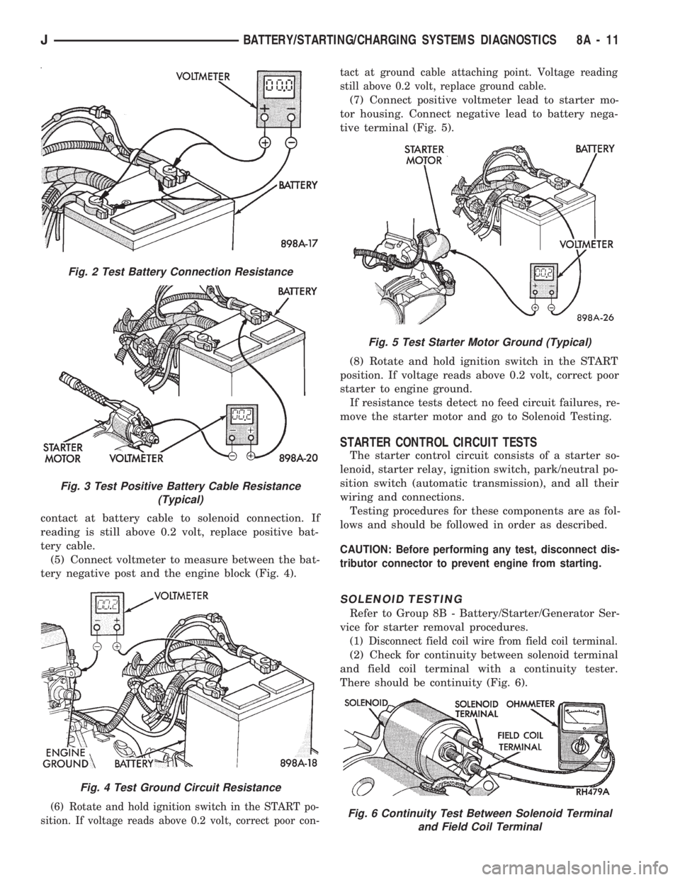
contact at battery cable to solenoid connection. If
reading is still above 0.2 volt, replace positive bat-
tery cable.
(5) Connect voltmeter to measure between the bat-
tery negative post and the engine block (Fig. 4).
(6) Rotate and hold ignition switch in the START po-
sition. If voltage reads above 0.2 volt, correct poor con-tact at ground cable attaching point. Voltage reading
still above 0.2 volt, replace ground cable.
(7) Connect positive voltmeter lead to starter mo-
tor housing. Connect negative lead to battery nega-
tive terminal (Fig. 5).
(8) Rotate and hold ignition switch in the START
position. If voltage reads above 0.2 volt, correct poor
starter to engine ground.
If resistance tests detect no feed circuit failures, re-
move the starter motor and go to Solenoid Testing.
STARTER CONTROL CIRCUIT TESTS
The starter control circuit consists of a starter so-
lenoid, starter relay, ignition switch, park/neutral po-
sition switch (automatic transmission), and all their
wiring and connections.
Testing procedures for these components are as fol-
lows and should be followed in order as described.
CAUTION: Before performing any test, disconnect dis-
tributor connector to prevent engine from starting.
SOLENOID TESTING
Refer to Group 8B - Battery/Starter/Generator Ser-
vice for starter removal procedures.
(1) Disconnect field coil wire from field coil terminal.
(2) Check for continuity between solenoid terminal
and field coil terminal with a continuity tester.
There should be continuity (Fig. 6).
Fig. 2 Test Battery Connection Resistance
Fig. 3 Test Positive Battery Cable Resistance
(Typical)
Fig. 4 Test Ground Circuit Resistance
Fig. 5 Test Starter Motor Ground (Typical)
Fig. 6 Continuity Test Between Solenoid Terminal
and Field Coil Terminal
JBATTERY/STARTING/CHARGING SYSTEMS DIAGNOSTICS 8A - 11
Page 314 of 1784

IGNITION SYSTEMS
CONTENTS
page page
COMPONENT IDENTIFICATION/SYSTEM
OPERATION.......................... 1
COMPONENT REMOVAL/INSTALLATION..... 20DIAGNOSTICS/SERVICE PROCEDURES....... 8
IGNITION SWITCH...................... 30
SPECIFICATIONS....................... 33
COMPONENT IDENTIFICATION/SYSTEM OPERATION
INDEX
page page
Automatic Shut Down (ASD) Relay............ 1
Camshaft Position Sensor................... 1
Crankshaft Position Sensor.................. 2
Distributors.............................. 3
Engine Coolant Temperature Sensor........... 4
General Information........................ 1Ignition Coil.............................. 4
Intake Manifold Air Temperature Sensor........ 5
Manifold Absolute Pressure (MAP) Sensor...... 5
Powertrain Control Module (PCM)............. 6
Throttle Position Sensor.................... 6
GENERAL INFORMATION
Throughout this group, references are made to par-
ticular vehicle models by alphabetical designation
(XJ or YJ) or by the particular vehicle nameplate. A
chart showing a breakdown of alphabetical designa-
tions is included in the Introduction group at the be-
ginning of this manual.
This section of the group, Component Identifica-
tion/System Operation, will discuss ignition system
operation and will identify ignition system compo-
nents.
For diagnostic procedures and adjustments, refer to
the Diagnostics/Service Procedures section of this
group.
For removal and installation of ignition system
components, refer to the Component Removal/Instal-
lation section of this group.
For other useful information, refer to On-Board Di-
agnostics in the General Diagnosis sections of Group
14, Fuel System in this manual.
For operation of the DRB Scan Tool, refer to the
appropriate Powertrain Diagnostic Procedures ser-
vice manual.
An Ignition specifications section is included at the
end of this group. A general Maintenance Schedule
(mileage intervals) for ignition related items can be
found in Group 0, Lubrication and Maintenance. This
schedule can also be found in the Owners Manual.
IGNITION SYSTEMS
A multi-port, fuel injected engine is used on all
models. The ignition system is controlled by the Pow-
ertrain Control Module (PCM) on all engines. The
PCM was formerly referred to as the SBEC or engine
controller.
The ignition system consists of:
²Spark Plugs
²Ignition Coil
²Secondary Ignition Cables
²Ignition distributor (contains rotor and camshaft
position sensor)
²Powertrain Control Module (PCM)
²Crankshaft Position Sensor
AUTOMATIC SHUT DOWN (ASD) RELAY
The automatic shut down (ASD) relay is located in
the Power Distribution Center (PDC) near the bat-
tery (Fig. 1 or 2). As one of its functions, it will sup-
ply battery voltage to the ignition coil. The ground
circuit for the ASD relay is controlled by the Power-
train Control Module (PCM). The PCM regulates
ASD relay operation by switching the ground circuit
on-and-off.
CAMSHAFT POSITION SENSOR
The camshaft position sensor is located in the igni-
tion distributor (Figs. 3 or 4) on all engines.
The camshaft position sensor contains a hall effect
device called a sync signal generator to generate a
fuel sync signal. This sync signal generator detects a
JIGNITION SYSTEMS 8D - 1