1994 JEEP CHEROKEE check engine
[x] Cancel search: check enginePage 145 of 1784
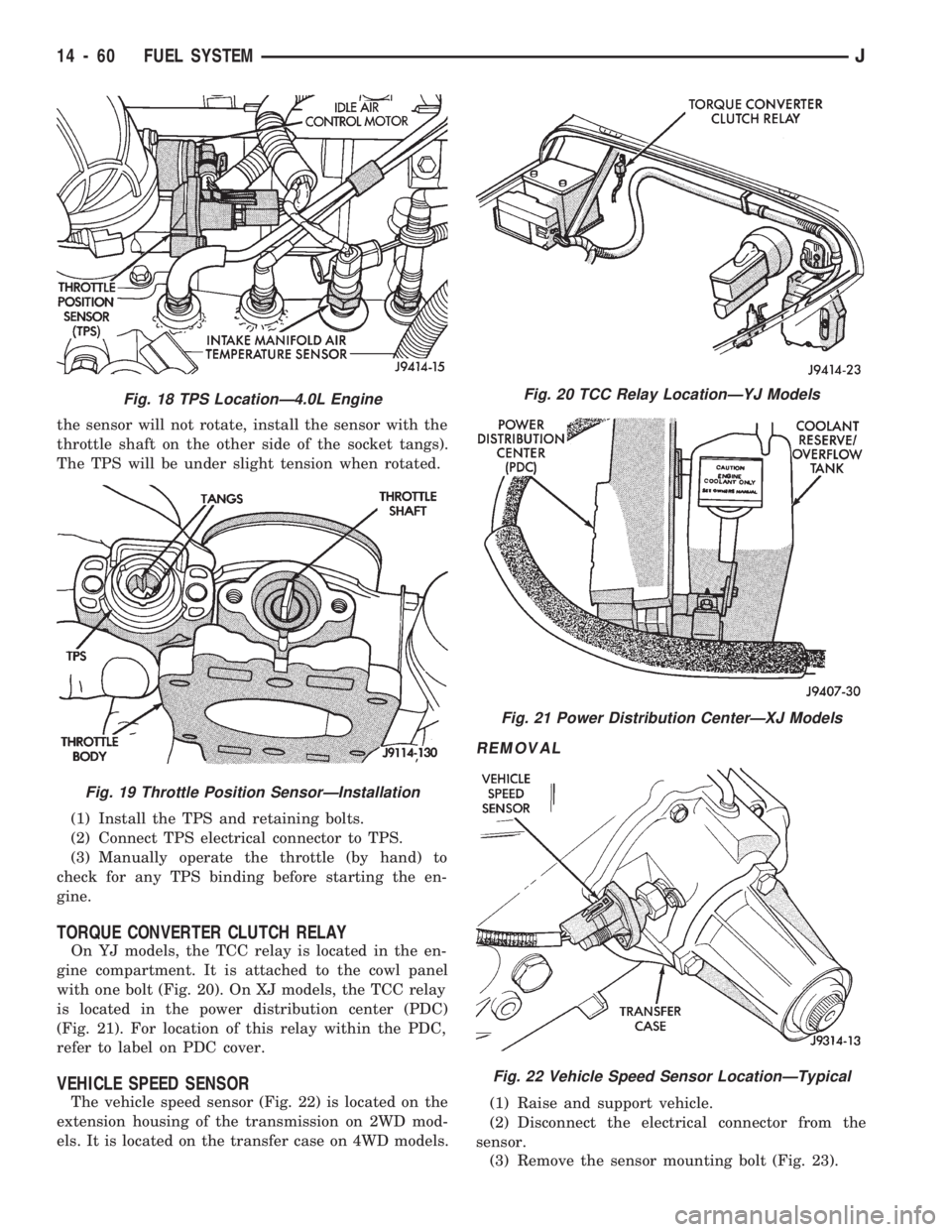
the sensor will not rotate, install the sensor with the
throttle shaft on the other side of the socket tangs).
The TPS will be under slight tension when rotated.
(1) Install the TPS and retaining bolts.
(2) Connect TPS electrical connector to TPS.
(3) Manually operate the throttle (by hand) to
check for any TPS binding before starting the en-
gine.
TORQUE CONVERTER CLUTCH RELAY
On YJ models, the TCC relay is located in the en-
gine compartment. It is attached to the cowl panel
with one bolt (Fig. 20). On XJ models, the TCC relay
is located in the power distribution center (PDC)
(Fig. 21). For location of this relay within the PDC,
refer to label on PDC cover.
VEHICLE SPEED SENSOR
The vehicle speed sensor (Fig. 22) is located on the
extension housing of the transmission on 2WD mod-
els. It is located on the transfer case on 4WD models.
REMOVAL
(1) Raise and support vehicle.
(2) Disconnect the electrical connector from the
sensor.
(3) Remove the sensor mounting bolt (Fig. 23).
Fig. 18 TPS LocationÐ4.0L Engine
Fig. 19 Throttle Position SensorÐInstallation
Fig. 20 TCC Relay LocationÐYJ Models
Fig. 21 Power Distribution CenterÐXJ Models
Fig. 22 Vehicle Speed Sensor LocationÐTypical
14 - 60 FUEL SYSTEMJ
Page 151 of 1784

scan tool will be necessary to determine which ABS
component has malfunctioned.
ABS Light Illuminates During Brake Stop
A system fault such as loss of speed sensor signal
or solenoid failure, will cause the amber warning
light to illuminate. The most effective procedure here
is to check for obvious damage first. Then check the
electronic components with the DRB II scan tool.
BRAKE WARNING LIGHT DISPLAY
The red brake warning light and the ABS light op-
erate independently. If the red light remains on after
startup or illuminates during a brake stop, refer to
the standard brake system diagnosis section. Either
the parking brakes are applied, or a wheel brake
malfunction has occurred.
ECU DIAGNOSIS
The ECU controls all phases of antilock system op-
eration. It also differentiates between normal and an-
tilock mode braking.
The ECU monitors and processes the signals gen-
erated from all of the system sensors at all times.
The ECU program includes a self check routine
that tests each of the system components. The self
check occurs during both phases of the initialization
program. A failure of the self check program will
cause the immediate illumination of the amber warn-
ing light. The light will also illuminate if a solenoid
or other system component fails during the dynamic
phase of initialization.
If a system malfunction should occur, do not imme-
diately replace the ECU. A blown system fuse, bad
chassis ground, or loss of feed voltage will each cause
a system malfunction similar to an ECU failure.
Never replace the ECU unless diagnosis with the
DRB II scan tool indicates this is necessary.
HCU DIAGNOSIS
The HCU pump and motor and solenoid valve body
are serviced only as an assembly. The HCU assembly
should not be replaced unless a fault has actually
been confirmed. Verify fault conditions with the DRB
II scan tool before proceeding with repair.
ABS SYSTEM WIRING AND ELECTRICAL CIRCUITS
Location of the ABS fuse (in the fuse panel) is
shown in Figure 1. The engine compartment harness
routing for the ABS components is shown in Figure 2.
ABS FAULT DIAGNOSIS
The fault diagnosis chart provides additional infor-
mation on potential ABS system faults. Use the
chart as a guide when diagnosing a system problem.
Fig. 1 ABS Fuse Location
5 - 4 BRAKESJ
Page 155 of 1784
(2) If red warning light is illuminated, or if neither
warning light is illuminated, make several stops and
note pedal action and brake response.
(3) Check brake pedal response with transmission
in Neutral and engine running. Pedal should remain
firm under steady foot pressure. If pedal falls away,
problem is either in vacuum booster or master cylin-
der.
(4) During road test, make normal and firm brake
stops in 25-40 mph range. Note faulty brake opera-
tion such as pull, grab, drag, noise, fade, pedal pul-
sation, etc.
(5) Inspect suspect brake components and refer to
problem diagnosis information for causes of various
brake conditions.
COMPONENT INSPECTION
Fluid leak points and dragging brake units can
usually be located without removing any compo-
nents. The area around a leak point will be wet with
fluid. The components at a dragging brake unit
(wheel, tire, rotor) will be quite warm or hot to the
touch.
Other brake problem conditions will require compo-
nent removal for proper inspection. Raise the vehicle
and remove the necessary wheels for better visual ac-
cess.
During component inspection, pay particular atten-
tion to heavily rusted/corroded brake components
(e.g. rotors, caliper pistons, brake return/holddown
springs, support plates, etc.).
Heavy accumulations of rust may be covering se-
vere damage to a brake component. It is wise to re-
move surface rust in order to accurately determine
the depth of rust penetration and damage. Light sur-
face rust is fairly normal and not a major concern (as
long as it is removed). However, heavy rust buildup,
especially on high mileage vehicles may cover struc-
tural damage to such important components as
brakelines, rotors, support plates, and brake boosters.
Refer to the wheel brake service procedures in this
group for more information.
DIAGNOSING SERVICE BRAKE PROBLEMS
BRAKE WARNING LIGHT OPERATION
The red brake warning light will illuminate under
the following conditions:
²for 2-3 seconds at startup as part of normal bulb
check
²parking brakes applied
²low pedal caused by malfunction in front/rear
brake hydraulic circuit (differential switch valve ac-
tuated)
If the red light remains on after startup, first ver-
ify that the parking brakes are fully released. Then
check pedal action and fluid level. A red light indi-
cates that the valve in the differential pressureswitch has been actuated. If a problem is confirmed,
inspect the hydraulic system and wheel brake compo-
nents.
On models with ABS brakes, the amber warning
light only illuminates when an ABS component has
malfunctioned. The ABS light operates indepen-
dently of the red warning light. Refer to the antilock
brake section for more detailed diagnosis informa-
tion.
PEDAL FALLS AWAY
A brake pedal that falls away under steady foot
pressure is generally the result of a system leak. The
leak point could be at a brakeline, fitting, hose,
wheel cylinder, or caliper. Internal leakage in the
master cylinder caused by worn or damaged piston
cups, may also be the problem cause.
If leakage is severe, fluid will be evident at or
around the leaking component. However internal
leakage in the master cylinder will not be physically
evident. Refer to the cylinder test procedure in this
section.
LOW PEDAL
If a low pedal is experienced, pump the pedal sev-
eral times. If the pedal comes back up, worn lining
and worn rotors or drums are the most likely causes.
However, if the pedal remains low and/or the warn-
ing light illuminates, the problem is in the master
cylinder, wheel cylinders, or calipers.
A decrease in master cylinder fluid level may only
be the result of normal lining wear. Fluid level will
decrease as lining wear occurs. It is a result of the
outward movement of caliper and wheel cylinder pis-
tons to compensate for normal wear.
SPONGY PEDAL
A spongy pedal is most often caused by air in the
system. However, thin drums or substandard brake
lines and hoses will also cause a condition similar to
a spongy pedal. The proper course of action is to
bleed the system, or replace thin drums and suspect
quality brake lines and hoses.
HARD PEDAL OR HIGH PEDAL EFFORT
A hard pedal or high pedal effort may be due to
lining that is water soaked, contaminated, glazed, or
badly worn. The power booster or check valve could
also be faulty. Test the booster and valve as de-
scribed in this section.
BRAKE DRAG
Brake drag occurs when the lining is in constant
contact with the rotor or drum. Drag can occur at
one wheel, all wheels, fronts only, or rears only. It is
a product of incomplete brakeshoe release. Drag can
be minor or severe enough to overheat the linings,
rotors and drums.
5 - 8 BRAKESJ
Page 158 of 1784
assembled, they will not function. In addition, since
the adjuster mechanism only works during reverse
stops, it is important that complete stops be made.
The adjuster mechanism does not operate when roll-
ing stops are made in reverse. The vehicle must be
brought to a complete halt before the adjuster lever
will turn the adjuster screw.
A condition where the parking brakes do not hold,
will most probably be due to a wheel brake compo-
nent.
Items to look for when diagnosing a parking brake
problem, are:
²rear brakeshoe wear
²rear brakedrum wear
²brakedrums machined beyond allowable diameter
(oversize)
²parking brake front cable not secured to lever
²parking brake rear cable seized
²parking brake strut reversed
²parking brake strut not seated in both shoes
²parking brake lever not seated in secondary shoe
²parking brake lever or brakeshoe bind on support
plate
²brakeshoes reversed
²adjuster screws seized
²adjuster screws reversed
²holddown or return springs misassembled or lack
tension
²wheel cylinder pistons seized
Brake drums that are machined oversize are diffi-
cult to identify. If oversize drums are suspected, the
diameter of the braking surface will have to be
checked with an accurate drum gauge. Oversize
drums will cause low brake pedal and lack of park-
ing brake holding ability.
Improper parking brake strut and lever installa-
tion will result in unsatisfactory parking brake oper-
ation. Intermixing the adjuster screws will cause
drag, bind and pull along with poor parking brake
operation.
Parking brake adjustment and parts replacement
procedures are described in the Parking Brake sec-
tion.
MASTER CYLINDER/POWER BOOSTER TEST
(1) Start engine and check booster vacuum hose
connections. Hissing noise indicates vacuum leak.
Correct any vacuum leak before proceeding.
(2) Stop engine and shift transmission into Neu-
tral.
(3) Pump brake pedal until all vacuum reserve in
booster is depleted.
(4) Press and hold brake pedal under light foot
pressure.
(a) If pedal holds firm, proceed to step (5).
(b) If pedal does not hold firm and falls away,
master cylinder is faulty (internal leakage). Over-
haul or replace cylinder.(5) Start engine and note pedal action.
(a) If pedal falls away slightly under light foot
pressure then holds firm, proceed to step (6).
(b) If no pedal action is discernible, power
booster or vacuum check valve is faulty. Install
known good check valve and repeat steps (2)
through (5).
(6) Rebuild booster vacuum reserve as follows: Re-
lease brake pedal. Increase engine speed to 1500
rpm, close throttle and immediately turn off ignition.
(7) Wait a minimum of 90 seconds and try brake
action again. Booster should provide two or more
vacuum assisted pedal applications. If vacuum assist
is not provided, perform booster and check valve vac-
uum tests.
POWER BOOSTER CHECK VALVE TEST
(1) Disconnect vacuum hose from check valve.
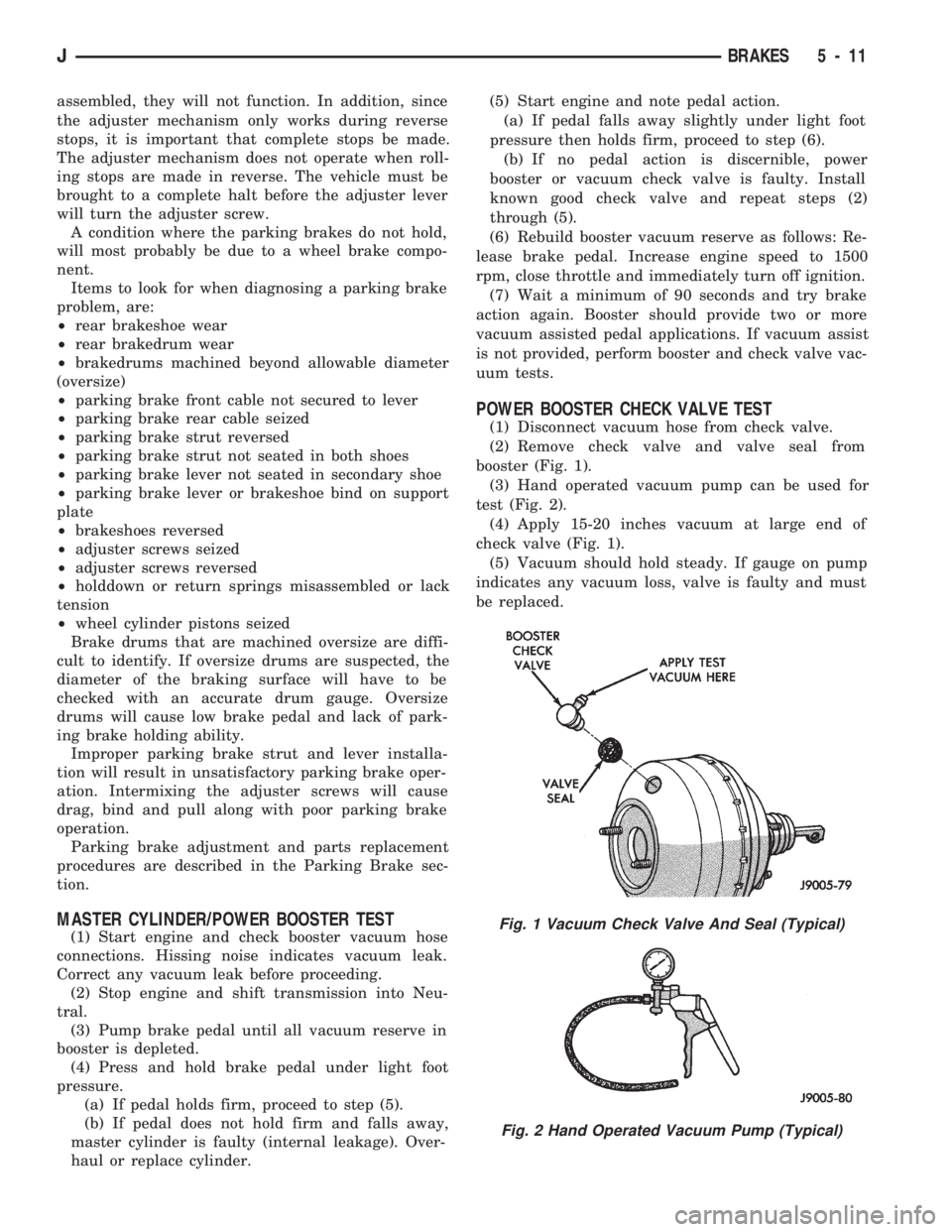
(2) Remove check valve and valve seal from
booster (Fig. 1).
(3) Hand operated vacuum pump can be used for
test (Fig. 2).
(4) Apply 15-20 inches vacuum at large end of
check valve (Fig. 1).
(5) Vacuum should hold steady. If gauge on pump
indicates any vacuum loss, valve is faulty and must
be replaced.
Fig. 1 Vacuum Check Valve And Seal (Typical)
Fig. 2 Hand Operated Vacuum Pump (Typical)
JBRAKES 5 - 11
Page 159 of 1784
POWER BOOSTER VACUUM TEST
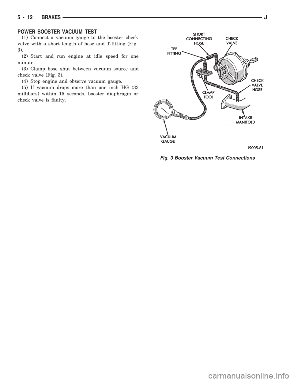
(1) Connect a vacuum gauge to the booster check
valve with a short length of hose and T-fitting (Fig.
3).
(2) Start and run engine at idle speed for one
minute.
(3) Clamp hose shut between vacuum source and
check valve (Fig. 3).
(4) Stop engine and observe vacuum gauge.
(5) If vacuum drops more than one inch HG (33
millibars) within 15 seconds, booster diaphragm or
check valve is faulty.
Fig. 3 Booster Vacuum Test Connections
5 - 12 BRAKESJ
Page 169 of 1784
POWER BRAKE BOOSTER
INDEX
page page
Power Brake Booster Installation............. 23
Power Brake Booster Operation............. 22Power Brake Booster Removal.............. 22
Service Information....................... 22
SERVICE INFORMATION
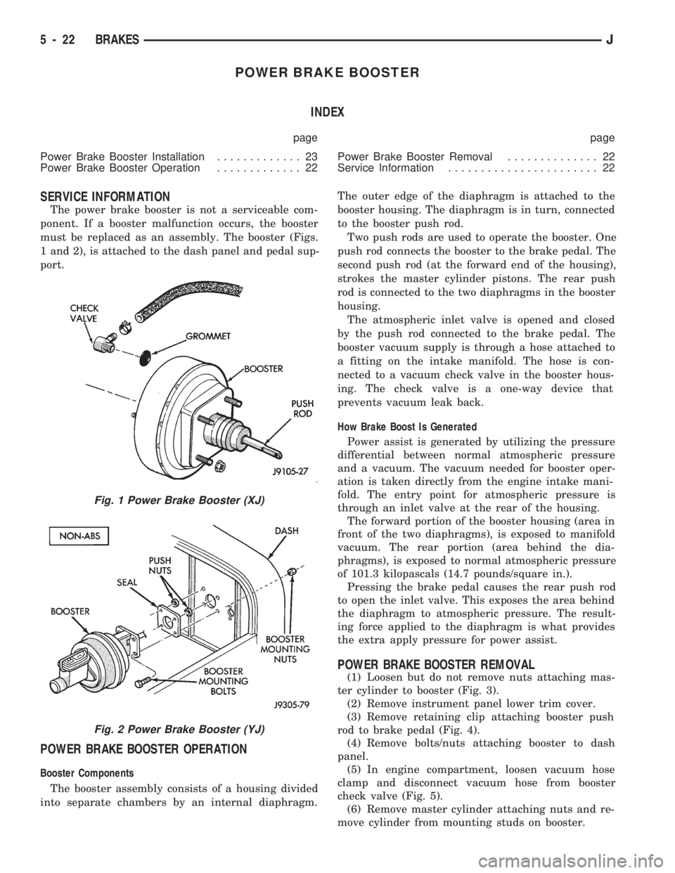
The power brake booster is not a serviceable com-
ponent. If a booster malfunction occurs, the booster
must be replaced as an assembly. The booster (Figs.
1 and 2), is attached to the dash panel and pedal sup-
port.
POWER BRAKE BOOSTER OPERATION
Booster Components
The booster assembly consists of a housing divided
into separate chambers by an internal diaphragm.The outer edge of the diaphragm is attached to the
booster housing. The diaphragm is in turn, connected
to the booster push rod.
Two push rods are used to operate the booster. One
push rod connects the booster to the brake pedal. The
second push rod (at the forward end of the housing),
strokes the master cylinder pistons. The rear push
rod is connected to the two diaphragms in the booster
housing.
The atmospheric inlet valve is opened and closed
by the push rod connected to the brake pedal. The
booster vacuum supply is through a hose attached to
a fitting on the intake manifold. The hose is con-
nected to a vacuum check valve in the booster hous-
ing. The check valve is a one-way device that
prevents vacuum leak back.
How Brake Boost Is Generated
Power assist is generated by utilizing the pressure
differential between normal atmospheric pressure
and a vacuum. The vacuum needed for booster oper-
ation is taken directly from the engine intake mani-
fold. The entry point for atmospheric pressure is
through an inlet valve at the rear of the housing.
The forward portion of the booster housing (area in
front of the two diaphragms), is exposed to manifold
vacuum. The rear portion (area behind the dia-
phragms), is exposed to normal atmospheric pressure
of 101.3 kilopascals (14.7 pounds/square in.).
Pressing the brake pedal causes the rear push rod
to open the inlet valve. This exposes the area behind
the diaphragm to atmospheric pressure. The result-
ing force applied to the diaphragm is what provides
the extra apply pressure for power assist.
POWER BRAKE BOOSTER REMOVAL
(1) Loosen but do not remove nuts attaching mas-
ter cylinder to booster (Fig. 3).
(2) Remove instrument panel lower trim cover.
(3) Remove retaining clip attaching booster push
rod to brake pedal (Fig. 4).
(4) Remove bolts/nuts attaching booster to dash
panel.
(5) In engine compartment, loosen vacuum hose
clamp and disconnect vacuum hose from booster
check valve (Fig. 5).
(6) Remove master cylinder attaching nuts and re-
move cylinder from mounting studs on booster.
Fig. 1 Power Brake Booster (XJ)
Fig. 2 Power Brake Booster (YJ)
5 - 22 BRAKESJ
Page 188 of 1784
4). The engine intake manifold serves as the vacuum
source for booster operation.
The booster is mounted on the engine compartment
side of the dash panel. The master cylinder is
mounted on attaching studs at the front of the
booster. The master cylinder central valves are di-
rectly actuated by the booster push rod.
The pedal travel sensor is mounted in the forward
face of the booster shell. The sensor plunger is actu-
ated by the booster diaphragm plate.
PEDAL TRAVEL SENSOR
The pedal travel sensor signals brake pedal posi-
tion to the antilock ECU. The sensor signal is based
on changes in electrical resistance. The resistance
changes occur in steps that are generated by changes
in brake pedal position. A resistance signal gener-
ated by changing brake pedal position, will cause the
ECU to run the antilock pump when necessary.
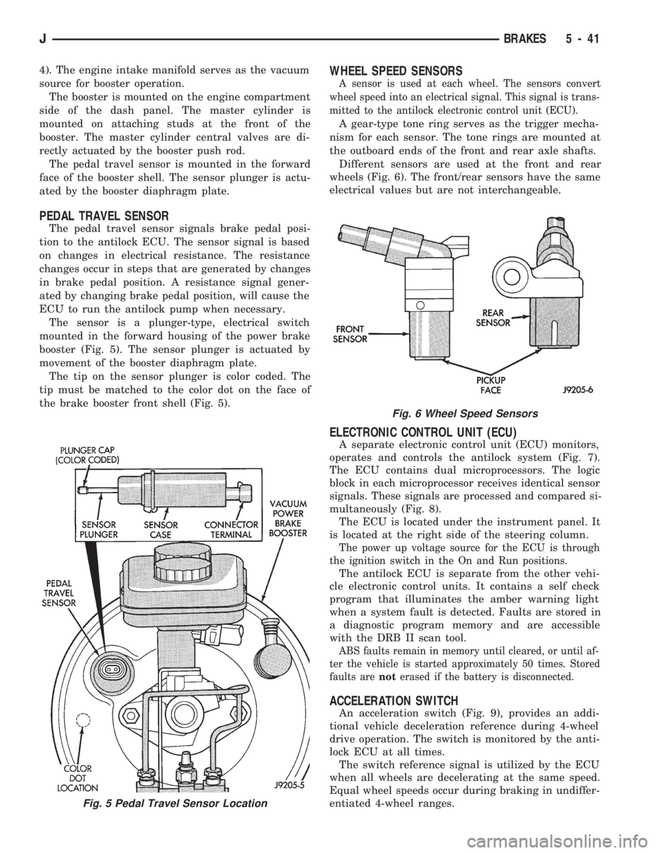
The sensor is a plunger-type, electrical switch
mounted in the forward housing of the power brake
booster (Fig. 5). The sensor plunger is actuated by
movement of the booster diaphragm plate.
The tip on the sensor plunger is color coded. The
tip must be matched to the color dot on the face of
the brake booster front shell (Fig. 5).
WHEEL SPEED SENSORS
A sensor is used at each wheel. The sensors convert
wheel speed into an electrical signal. This signal is trans-
mitted to the antilock electronic control unit (ECU).
A gear-type tone ring serves as the trigger mecha-
nism for each sensor. The tone rings are mounted at
the outboard ends of the front and rear axle shafts.
Different sensors are used at the front and rear
wheels (Fig. 6). The front/rear sensors have the same
electrical values but are not interchangeable.
ELECTRONIC CONTROL UNIT (ECU)
A separate electronic control unit (ECU) monitors,
operates and controls the antilock system (Fig. 7).
The ECU contains dual microprocessors. The logic
block in each microprocessor receives identical sensor
signals. These signals are processed and compared si-
multaneously (Fig. 8).
The ECU is located under the instrument panel. It
is located at the right side of the steering column.
The power up voltage source for the ECU is through
the ignition switch in the On and Run positions.
The antilock ECU is separate from the other vehi-
cle electronic control units. It contains a self check
program that illuminates the amber warning light
when a system fault is detected. Faults are stored in
a diagnostic program memory and are accessible
with the DRB II scan tool.
ABS faults remain in memory until cleared, or until af-
ter the vehicle is started approximately 50 times. Stored
faults arenoterased if the battery is disconnected.
ACCELERATION SWITCH
An acceleration switch (Fig. 9), provides an addi-
tional vehicle deceleration reference during 4-wheel
drive operation. The switch is monitored by the anti-
lock ECU at all times.
The switch reference signal is utilized by the ECU
when all wheels are decelerating at the same speed.
Equal wheel speeds occur during braking in undiffer-
entiated 4-wheel ranges.
Fig. 5 Pedal Travel Sensor Location
Fig. 6 Wheel Speed Sensors
JBRAKES 5 - 41
Page 196 of 1784
Clean the reservoir and caps thoroughly before
checking level or adding fluid. Cap open lines and
hoses during service to prevent dirt entry.
Dirt or foreign material entering the ABS hydrau-
lic system through the reservoir opening will circu-
late within the system. The result will be poor brake
performance and possible component failure. Use
clean, fresh fluid only to top off, or refill the system.
WHEEL SENSOR AIR GAP ADJUSTMENT
Only rear sensor air gap is adjustable. The front
sensors are fixed and cannot be adjusted.
A rear sensor air gap adjustment is only
needed when reinstalling an original sensor. Re-
placement sensors have an air gap spacer at-
tached to the sensor pickup face. The spacer
establishes correct air gap when pressed against
the tone ring during installation. As the tone
ring rotates, it peels the spacer off the sensor to
create the required air gap.
Preferred rear sensor air gap is 1.1 mm (0.043 in.).
Acceptable air gap range is 0.92 to 1.275 mm (0.036
to 0.050 in.).
Front sensor air gap is not adjustable. The front
sensors are fixed in position and cannot be adjusted.
Front sensor air gap can only be checked. Air gap
should be 0.040 to 1.3 mm (0.0157 to 0.051 in.). If
front sensor air gap is incorrect, the sensor is either
loose, or damaged.
FRONT WHEEL SENSOR REMOVAL
(1) Raise vehicle and turn wheel outward for eas-
ier access to sensor.
(2) Remove sensor wire from mounting brackets.
(3) Clean sensor and surrounding area before removal.
(4) Remove bolt attaching sensor to steering
knuckle and remove sensor.
(5) Unseat grommet retaining sensor wire in wheel
house panel.
(6) In engine compartment, disconnect sensor wire con-
nector at harness plug. Then remove sensor and wire.
FRONT WHEEL SENSOR INSTALLATION
(1) Apply Mopar Lock N' Seal or Loctite 242 to
bolt that attaches sensor to steering knuckle. Use
new sensor bolt if original bolt is worn or damaged.
(2) Position sensor on steering knuckle. Seat sen-
sor locating tab in hole in knuckle and install sensor
attaching bolt finger tight.
(3) Tighten sensor bolt to 14 NIm (11 ft. lbs.) torque.
(4) Attach sensor wire to steering knuckle bracket
with grommets on sensor wire.
(5) Route sensor wire forward and behind shock
absorber. Then attach sensor wire to spring seat
bracket with grommets on sensor wire.
(6) Route sensor wire to outer sill bracket. Remove
all twists or kinks from wire.(7) Attach sensor wire to sill bracket with grom-
met. Be sure wire is free of twists and kinks.
(8) Verify sensor wire routing. Wire should loop
forward and above sill bracket. Loose end of wire
should be below sill bracket and towards brake hose.
(9) Seat sensor wire grommet in body panel and
clip wire to brake line at grommet location.
(10) Connect sensor wire to harness in engine com-
partment.
REAR WHEEL SENSOR REMOVAL
(1) On XJ models, if separate connectors are not
used to attach sensor harness to each sensor wire,
proceed as follows:
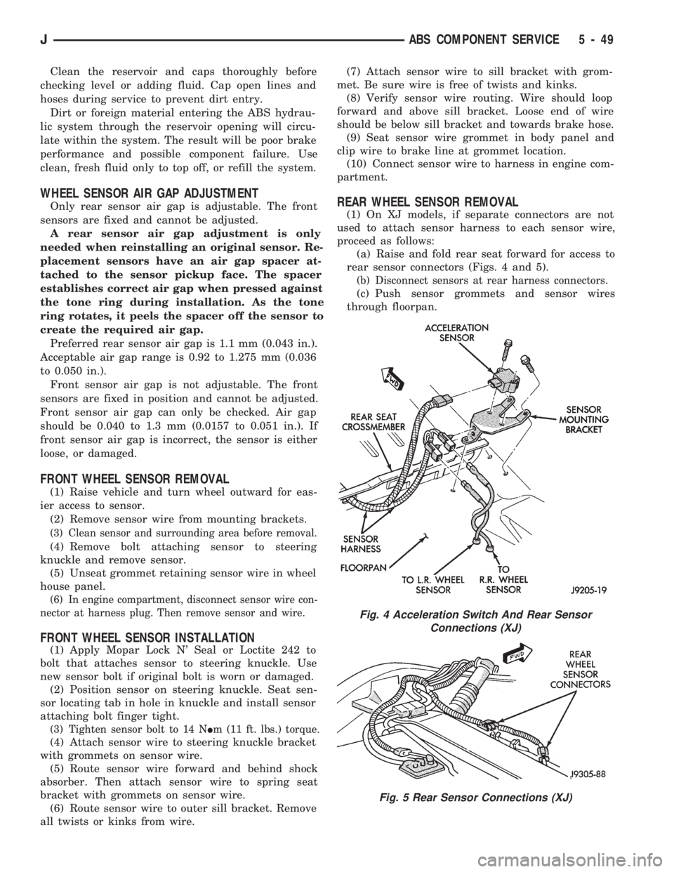
(a) Raise and fold rear seat forward for access to
rear sensor connectors (Figs. 4 and 5).
(b) Disconnect sensors at rear harness connectors.
(c) Push sensor grommets and sensor wires
through floorpan.
Fig. 4 Acceleration Switch And Rear Sensor
Connections (XJ)
Fig. 5 Rear Sensor Connections (XJ)
JABS COMPONENT SERVICE 5 - 49