1994 JEEP CHEROKEE oil change
[x] Cancel search: oil changePage 318 of 1784
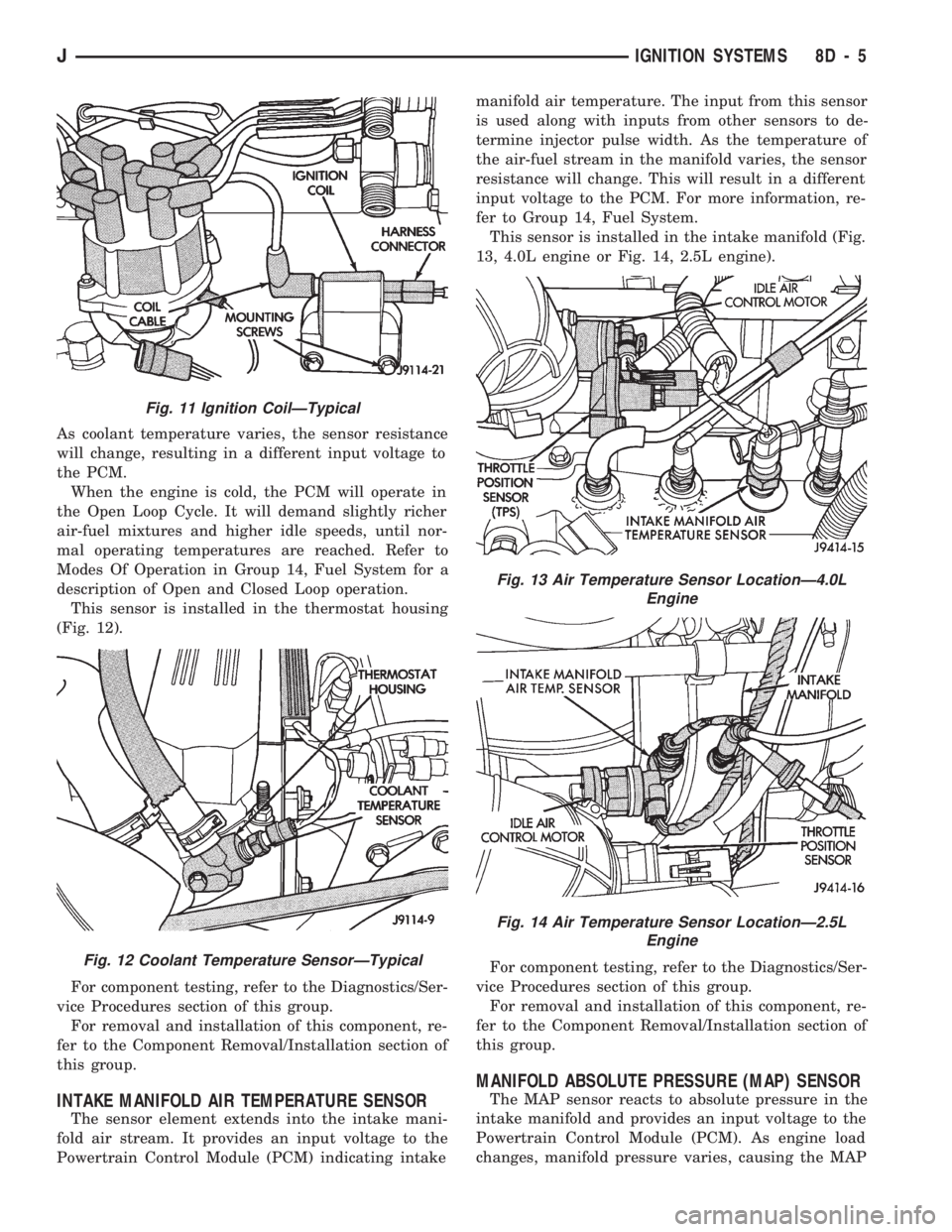
As coolant temperature varies, the sensor resistance
will change, resulting in a different input voltage to
the PCM.
When the engine is cold, the PCM will operate in
the Open Loop Cycle. It will demand slightly richer
air-fuel mixtures and higher idle speeds, until nor-
mal operating temperatures are reached. Refer to
Modes Of Operation in Group 14, Fuel System for a
description of Open and Closed Loop operation.
This sensor is installed in the thermostat housing
(Fig. 12).
For component testing, refer to the Diagnostics/Ser-
vice Procedures section of this group.
For removal and installation of this component, re-
fer to the Component Removal/Installation section of
this group.
INTAKE MANIFOLD AIR TEMPERATURE SENSOR
The sensor element extends into the intake mani-
fold air stream. It provides an input voltage to the
Powertrain Control Module (PCM) indicating intakemanifold air temperature. The input from this sensor
is used along with inputs from other sensors to de-
termine injector pulse width. As the temperature of
the air-fuel stream in the manifold varies, the sensor
resistance will change. This will result in a different
input voltage to the PCM. For more information, re-
fer to Group 14, Fuel System.
This sensor is installed in the intake manifold (Fig.
13, 4.0L engine or Fig. 14, 2.5L engine).
For component testing, refer to the Diagnostics/Ser-
vice Procedures section of this group.
For removal and installation of this component, re-
fer to the Component Removal/Installation section of
this group.
MANIFOLD ABSOLUTE PRESSURE (MAP) SENSOR
The MAP sensor reacts to absolute pressure in the
intake manifold and provides an input voltage to the
Powertrain Control Module (PCM). As engine load
changes, manifold pressure varies, causing the MAP
Fig. 11 Ignition CoilÐTypical
Fig. 12 Coolant Temperature SensorÐTypical
Fig. 13 Air Temperature Sensor LocationÐ4.0L
Engine
Fig. 14 Air Temperature Sensor LocationÐ2.5L
Engine
JIGNITION SYSTEMS 8D - 5
Page 319 of 1784
sensor voltage to change. This change results in a
different input voltage to the PCM. The input volt-
age level supplies the PCM with information. This
relates to ambient barometric pressure during engine
start-up (cranking) and to engine load while the en-
gine is running. The PCM uses this input, along with
inputs from other sensors, to adjust air-fuel mixture.
For more information, refer to Group 14, Fuel Sys-
tem.
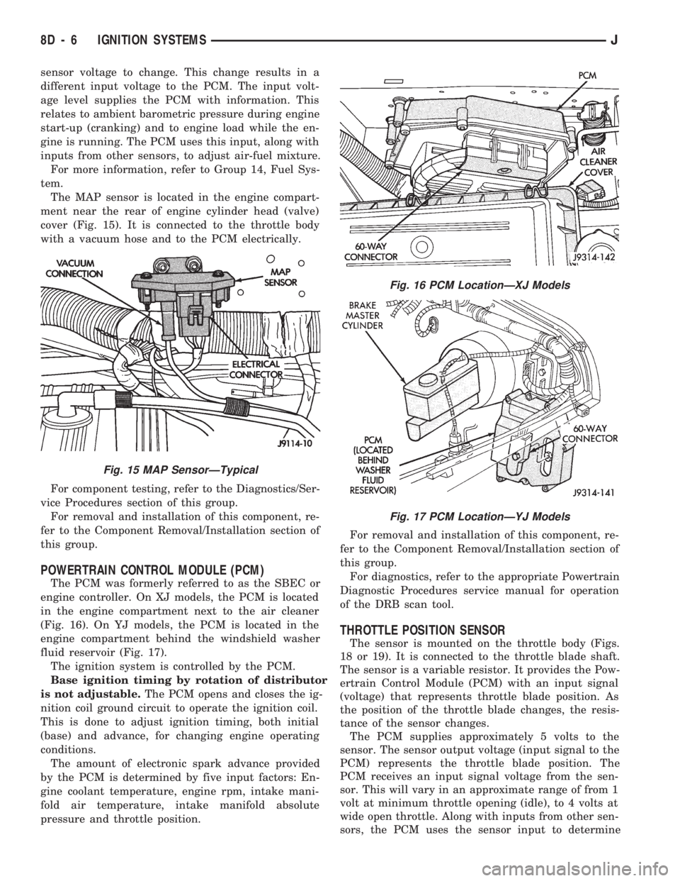
The MAP sensor is located in the engine compart-
ment near the rear of engine cylinder head (valve)
cover (Fig. 15). It is connected to the throttle body
with a vacuum hose and to the PCM electrically.
For component testing, refer to the Diagnostics/Ser-
vice Procedures section of this group.
For removal and installation of this component, re-
fer to the Component Removal/Installation section of
this group.
POWERTRAIN CONTROL MODULE (PCM)
The PCM was formerly referred to as the SBEC or
engine controller. On XJ models, the PCM is located
in the engine compartment next to the air cleaner
(Fig. 16). On YJ models, the PCM is located in the
engine compartment behind the windshield washer
fluid reservoir (Fig. 17).
The ignition system is controlled by the PCM.
Base ignition timing by rotation of distributor
is not adjustable.The PCM opens and closes the ig-
nition coil ground circuit to operate the ignition coil.
This is done to adjust ignition timing, both initial
(base) and advance, for changing engine operating
conditions.
The amount of electronic spark advance provided
by the PCM is determined by five input factors: En-
gine coolant temperature, engine rpm, intake mani-
fold air temperature, intake manifold absolute
pressure and throttle position.For removal and installation of this component, re-
fer to the Component Removal/Installation section of
this group.
For diagnostics, refer to the appropriate Powertrain
Diagnostic Procedures service manual for operation
of the DRB scan tool.
THROTTLE POSITION SENSOR
The sensor is mounted on the throttle body (Figs.
18 or 19). It is connected to the throttle blade shaft.
The sensor is a variable resistor. It provides the Pow-
ertrain Control Module (PCM) with an input signal
(voltage) that represents throttle blade position. As
the position of the throttle blade changes, the resis-
tance of the sensor changes.
The PCM supplies approximately 5 volts to the
sensor. The sensor output voltage (input signal to the
PCM) represents the throttle blade position. The
PCM receives an input signal voltage from the sen-
sor. This will vary in an approximate range of from 1
volt at minimum throttle opening (idle), to 4 volts at
wide open throttle. Along with inputs from other sen-
sors, the PCM uses the sensor input to determine
Fig. 15 MAP SensorÐTypical
Fig. 16 PCM LocationÐXJ Models
Fig. 17 PCM LocationÐYJ Models
8D - 6 IGNITION SYSTEMSJ
Page 342 of 1784
cleaning, file the center electrode flat with a small
point file or jewelers file before adjusting gap.
PLUG GAP ADJUSTMENT
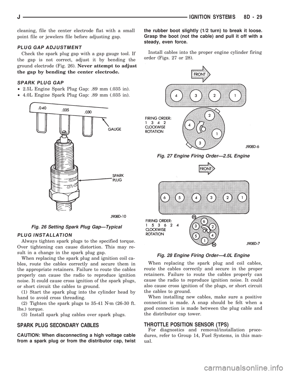
Check the spark plug gap with a gap gauge tool. If
the gap is not correct, adjust it by bending the
ground electrode (Fig. 26).Never attempt to adjust
the gap by bending the center electrode.
SPARK PLUG GAP
²2.5L Engine Spark Plug Gap: .89 mm (.035 in).
²4.0L Engine Spark Plug Gap: .89 mm (.035 in).
PLUG INSTALLATION
Always tighten spark plugs to the specified torque.
Over tightening can cause distortion. This may re-
sult in a change in the spark plug gap.
When replacing the spark plug and ignition coil ca-
bles, route the cables correctly and secure them in
the appropriate retainers. Failure to route the cables
properly can cause the radio to reproduce ignition
noise. It could cause cross ignition of the spark plugs,
or short circuit the cables to ground.
(1) Start the spark plug into the cylinder head by
hand to avoid cross threading.
(2) Tighten the spark plugs to 35-41 Nzm (26-30 ft.
lbs.) torque.
(3) Install spark plug cables over spark plugs.
SPARK PLUG SECONDARY CABLES
CAUTION: When disconnecting a high voltage cable
from a spark plug or from the distributor cap, twistthe rubber boot slightly (1/2 turn) to break it loose.
Grasp the boot (not the cable) and pull it off with a
steady, even force.
Install cables into the proper engine cylinder firing
order (Figs. 27 or 28).
When replacing the spark plug and coil cables,
route the cables correctly and secure in the proper
retainers. Failure to route the cables properly can
cause the radio to reproduce ignition noise. It could
also cause cross ignition of the plugs, or short circuit
the cables to ground.
When installing new cables, make sure a positive
connection is made. A snap should be felt when a
good connection is made between the plug cable and
the distributor cap tower.
THROTTLE POSITION SENSOR (TPS)
For diagnostics and removal/installation proce-
dures, refer to Group 14, Fuel Systems, in this man-
ual.
Fig. 26 Setting Spark Plug GapÐTypical
Fig. 27 Engine Firing OrderÐ2.5L Engine
Fig. 28 Engine Firing OrderÐ4.0L Engine
JIGNITION SYSTEMS 8D - 29
Page 348 of 1784

INSTRUMENT PANEL AND GAUGES
GROUP INDEX
page page
INSTRUMENT PANEL AND GAUGESÐXJ..... 1INSTRUMENT PANEL AND GAUGESÐYJ.... 14
INSTRUMENT PANEL AND GAUGESÐXJE
CONTENTS
page page
INSTRUMENT CLUSTER DIAGNOSIS........ 3
INSTRUMENT CLUSTER GENERAL INFORMATION.. 1
INSTRUMENT CLUSTER SERVICE PROCEDURES... 5
SPECIFICATIONS....................... 13
INSTRUMENT CLUSTER GENERAL INFORMATION
INDEX
page page
4WD Indicator Lamp........................ 2
Anti-Lock Brake Indicator Lamp............... 2
Brake Indicator Lamp....................... 2
Coolant Temperature Gauge................. 1
Coolant Temperature Indicator Lamp........... 1
Fuel Gauge.............................. 2
Low Fuel Warning Lamp..................... 2Malfunction Indicator Lamp (Check Engine)...... 2
Oil Pressure Gauge....................... 1
Oil Pressure Indicator Lamp.................. 1
Speedometer/Odometer System.............. 2
Tachometer.............................. 2
Upshift Indicator Lamp...................... 2
Voltmeter............................... 1
With the ignition switch in the ON or START posi-
tion, voltage supplied to the instrument cluster is lim-
ited by fuse #17. The voltage is supplied to all the
gauges and indicator lamps through the instrument
cluster printed circuit.
With the ignition switch in the OFF position, volt-
age is not supplied to the instrument cluster and the
gauges do not indicate any vehicle condition.
VOLTMETER
The voltmeter measures battery or generator out-
put voltage, whichever is greater.
OIL PRESSURE GAUGE
The oil pressure gauge pointer position is controlled
by a magnetic field created by electrical current flow
through the coils within the gauge. A change in current
flow will change the magnetic field which changes the
pointer position. The oil pressure sender is a variable
resistor that changes electrical resistance with a change
in oil pressure (values shown in Specifications chart).
OIL PRESSURE INDICATOR LAMP
Voltage is supplied to one side of the indicator bulb
and the oil pressure switch is connected to the other
side. When oil pressure is too low the switch closes
providing a path to ground, and the indicator bulb
lights.
COOLANT TEMPERATURE GAUGE
The coolant temperature gauge pointer position is
controlled by a magnetic field created by electrical
current flow through the coils within the gauge. A
change in current flow will change the magnetic field
which changes the pointer position. The coolant tem-
perature sensor is a thermistor that changes electri-
cal resistance with a change in coolant temperature
(values shown in Specifications chart).
COOLANT TEMPERATURE INDICATOR LAMP
Voltage is supplied to one side of the indicator bulb
and the coolant temperature switch is connected to the
JINSTRUMENT PANEL AND GAUGES 8E - 1
Page 349 of 1784
other side. When coolant temperature is too high the
switch closes providing a path to ground, and the indi-
cator bulb lights.
TACHOMETER
The tachometer displays the engine speed (RPM).
With the engine running, the tachometer receives an
engine speed signal from the Powertrain Control
Module pin 43 (values shown in Specifications chart).
SPEEDOMETER/ODOMETER SYSTEM
The speedometer/odometer system consists of an elec-
tric speedometer and pushbutton reset odometer
mounted in the cluster. The system also includes the
wire harness from the cluster to the vehicle speed sen-
sor at the transmission, and the adapter and pinion in
the transmission. A signal is sent from a transmission
mounted vehicle speed sensor to the speedometer/odom-
eter circuitry through the wiring harness. Refer to
Group 21 - Transmission for selecting the proper pinion,
and selecting and indexing the proper adapter.
FUEL GAUGE
The fuel gauge pointer position is controlled by a
magnetic field created by electrical current flow through
the coils within the gauge. A change in current flow will
change the magnetic field which changes the pointer po-
sition. The fuel level sender is a variable resistor that
changes electrical resistance with a change of the level
of fuel in the tank (values shown in Specifications
chart).
LOW FUEL WARNING LAMP
The low fuel warning lamp will light when the fuel
level falls below approximately 4 gallons. A low fuel
warning module controls when the lamp will light.
When the module senses 66.5 ohms or less from the
fuel level sender for 10 continuous seconds, the lamp
will light. The lamp will remain on until the module
senses 63.5 ohms or more from the fuel level sender
for 20 continuous seconds.
UPSHIFT INDICATOR LAMP
Vehicles equipped with manual transmissions have an
optional upshift indicator lamp. The lamp is controlled
by the Powertrain Control Module. The lamp lights to
indicate when the driver should shift to the next high-
est gear for best fuel economy. The Powertrain Control
Module will turn the lamp off after 3 to 5 seconds if the
upshift is not performed. The lamp will remain off until
the vehicle stops accelerating and is brought back to the
range of lamp operation or shifted into another gear.
The indicator lamp is normally illuminated when
the ignition switch is turned ON and is turned off
when the engine is started. The lamp will be lighted
during engine operation according to engine speed
and load.
BRAKE INDICATOR LAMP
The brake indicator lamp warns the driver that the
parking brake is applied or that hydraulic pressure in
the split brake system is unequal.
Voltage is supplied through the brake indicator
bulb to 3 switches. A path to ground for the current
is available if:
²The brake warning switch is closed (with unequal
brake system hydraulic pressures), or
²
The ignition switch is in the START position (to test
the bulb), or
²The park brake switch is closed (with the parking
brake applied).
ANTI-LOCK BRAKE SYSTEM (ABS) INDICATOR
LAMP
The anti-lock brake system (ABS) lamp lights to in-
dicate a system self-check is in process at vehicle
start-up. If light remains on after start-up or comes
on and stays on while driving, it may indicate that
the ABS system has detected a malfunction or has
become inoperative.
4WD INDICATOR LAMP
COMMAND-TRAC 4WD
The PART TIME lamp lights when the vehicle is en-
gaged in four-wheel drive mode. Voltage is supplied to
one side of the indicator bulb. A switch in the transfer
case area is connected to the other side of the indicator
bulb. When the switch is closed, a path to ground is pro-
vided and the indicator bulb lights.
SELECT-TRAC 4WD
The four-wheel drive icon or FULL TIME lamp
lights when the vehicle is engaged in full time four-
wheel drive mode. The PART TIME lamp lights when
the vehicle is in part time four-wheel drive mode.
Voltage is supplied to one side of the indicators.
Switches in the transfer case area are connected to
the other side of the indicator bulbs. When a switch
is closed, a path to ground is provided and the indi-
cator bulb lights.
MALFUNCTION INDICATOR LAMP (CHECK ENGINE)
The Malfunction Indicator Lamp (Check Engine)
lights each time the ignition switch is turned ON and
stays on for 3 seconds as a bulb test.
If the PCM receives an incorrect signal or no signal
from certain sensors or emission related systems the
lamp is turned on (pin 32 of PCM). This is a warning
that the PCM has recorded a system or sensor mal-
function. In some cases when a diagnostic trouble
code is declared the PCM will go into a limp-in mode
in an attempt to keep the system operating. It sig-
nals an immediate need for service.
The lamp also can be used to display diagnostic
trouble codes (DTC). Cycle the ignition switch ON,
OFF, ON, OFF, ON within 5 seconds. This will allow
any trouble codes stored in the PCM memory to be
displayed in a series of flashes representing digits.
8E - 2 XJ INSTRUMENT PANEL AND GAUGESJ
Page 369 of 1784

GAUGE PACKAGE GENERAL INFORMATION
The gauge package contains 4 gauges and the 4
wheel drive indicator. The gauges have a common
battery feed from fuse #9 and ignition switch. Al-
though they have separate power sources, the 4
gauges share a common ground connection.
The voltmeter indicates electrical system voltage.
When the engine is not running, the voltage regis-
tered is from the battery. After the engine is started,
charging system voltage is indicated. In the gauge
package, the voltmeter forms a parallel connectionacross the battery feed and ground.
The remaining gauges - oil pressure, fuel and cool-
ant temperature - are connected to individual sender
units. Variable resistors in the senders will change
the amount of current allowed to flow through the
gauge coils. As current flow through the coils varies,
the position of the indicator needle also will vary.
The 4 gauges are connected to battery feed, ground
and the sender units through a printed circuit
mounted on the back of the gauge housing.
GAUGE PACKAGE DIAGNOSIS
ALL GAUGES INOPERATIVE (Fig. 15)
(1) Check the fuse #9. Replace as required.
(2) Turn ignition switch to ON and measure volt-
age at battery side of fuse #9. Meter should read bat-
tery voltage. If not, repair open from ignition switch.
(3) Unplug gauge package connector from gauge
package.
(4) Turn ignition switch to OFF and measure resis-
tance from instrument cluster connector terminals 1
and 13 to a clean chassis ground. Meter should read
zero ohms. If not, repair open to ground.
(5) Turn ignition switch to ON and measure volt-
age at instrument cluster connector terminals 2 and
12. Meter should read battery voltage. If not, repair
open from fuse panel.
ONE GAUGE INOPERATIVE
Does not apply to voltmeter.
OIL PRESSURE SENDER
(1) Turn ignition switch to ON.
(2) Unplug oil pressure sender connector from oil
pressure sender.
(3) Touch connector to engine block (ground).
Gauge should read at low end of scale.
(4) When connector is NOT touching ground (open
circuit) gauge should read at high end of scale. If OK
replace sender. If not, proceed with step 5.
(5) Check circuit between sender and gauge for an
open. Repair as required. If wiring is OK, replace
gauge.
COOLANT TEMPERATURE SENDER
(1) Turn ignition switch to ON.
(2) Unplug coolant temperature sender connector
from coolant temperature sender.
(3) Touch connector to engine block (ground).
Gauge should read at high end of scale.
(4) When connector is NOT touching ground (open
circuit) gauge should read at low end of scale. If OK
replace sender. If not, proceed with step 5.
(5) Check circuit between sender and gauge for an
open. Repair as required. If wiring is OK, replace
gauge.
FUEL GAUGE SENDER
(1) Turn ignition switch to ON.
(2) Separate fuel gauge sender connector from fuel
gauge sender near tank.
(3) Ground the center wire of the body harness
side of the connector. The gauge should read at low
end of scale. If OK, check sending unit (step 4). If
not, check circuit between connector and gauge. Re-
pair as required. If circuit is OK, replace gauge.
(4) Turn ignition switch to OFF.
(5) Measure resistance from fuel gauge sender con-
nector center terminal to a clean chassis ground.
Meter readings should correspond to those shown in
Specifications. If not OK, replace sender. If OK, re-
pair open from fuel gauge sender connector to
ground.
PRINTED CIRCUIT
(1) Turn ignition switch to ON.
(2) Unplug gauge package connector from gauge
package.
(3) Measure resistance from gauge package termi-
nal 12 (fuel and coolant temperature gauge) or from
terminal 2 (voltmeter and oil pressure gauge) to
gauge battery terminal. Meter should read zero
ohms. If not, replace/repair printed circuit.
(4) Measure resistance from gauge package termi-
nal 13 (fuel and coolant temperature gauge) or from
terminal 1 (voltmeter and oil pressure gauge) to
gauge ground terminal. Meter should read zero
ohms. If not, replace/repair printed circuit. If zero
ohms, replace gauge.
GAUGE CALIBRATION VALUES
Use the charts in Specifications. The calibration of
the gauge can be checked. If the indicator needle is
not in the correct position, replace the gauge.
4WD INDICATOR
The four-wheel drive indicator lamp circuit is com-
pleted by the Command-Trac switch located below
the battery.
8E - 22 YJ INSTRUMENT PANEL AND GAUGESJ
Page 842 of 1784
ENGINES
CONTENTS
page page
2.5L ENGINE SERVICE PROCEDURES....... 9
4.0L ENGINE SERVICE PROCEDURES...... 50ENGINE DIAGNOSIS...................... 5
STANDARD SERVICE PROCEDURES......... 1
STANDARD SERVICE PROCEDURES
INDEX
page page
Engine Performance....................... 2
Form-In-Place Gaskets..................... 1
Honing Cylinder Bores..................... 2
Hydrostatic Lock.......................... 4Measuring with Plastigage................... 3
Repair Damaged or Worn Threads............ 4
Service Engine Assembly (Short Block)......... 4
FORM-IN-PLACE GASKETS
There are several places where form-in-place gas-
kets are used on the engine.DO NOT use form-in-
place gasket material unless specified.Care must
be taken when applying form-in-place gaskets. Bead
size, continuity and location are of great importance.
Too thin a bead can result in leakage while too much
can result in spill-over. A continuous bead of the
proper width is essential to obtain a leak-free joint.
Two types of form-in-place gasket materials are
used in the engine area (Mopar Silicone Rubber Ad-
hesive Sealant and Mopar Gasket Maker). Each have
different properties and cannot be used interchange-
ably.
MOPAR SILICONE RUBBER ADHESIVE
SEALANT
Mopar Silicone Rubber Adhesive Sealant, normally
black in color, is available in 3 ounce tubes. Moisture
in the air causes the sealant material to cure. This
material is normally used on flexible metal flanges.
It has a shelf life of a year and will not properly cure
if over aged. Always inspect the package for the ex-
piration date before use.
MOPAR GASKET MAKER
Mopar Gasket Maker, normally red in color, is
available in 6 cc tubes. This anaerobic type gasket
material cures in the absence of air when squeezed
between smooth machined metallic surfaces. It will
not cure if left in the uncovered tube. DO NOT use
on flexible metal flanges.
SURFACE PREPARATION
Parts assembled with form-in-place gaskets may be
disassembled without unusual effort. In some in-
stances, it may be necessary to lightly tap the part
with a mallet or other suitable tool to break the seal
between the mating surfaces. A flat gasket scraper
may also be lightly tapped into the joint but care
must be taken not to damage the mating surfaces.
Scrape or wire brush all gasket surfaces to remove
all loose material. Inspect stamped parts to ensure
gasket rails are flat. Flatten rails with a hammer on
a flat plate, if required. Gasket surfaces must be free
of oil and dirt. Make sure the old gasket material is
removed from blind attaching holes.
GASKET APPLICATION
Assembling parts using a form-in-place gasket re-
quires care.
Mopar Silicone Rubber Adhesive Sealant should be
applied in a continuous bead approximately 3 mm
(0.12 inch) in diameter. All mounting holes must be
circled. For corner sealing,a3or6mm(1/8 or 1/4
inch) drop is placed in the center of the gasket con-
tact area. Uncured sealant may be removed with a
shop towel. Components should be torqued in place
while the sealant is still wet to the touch (within 10
minutes). The use of a locating dowel is recom-
mended during assembly to prevent smearing the
material off location.
Mopar Gasket Maker should be applied sparingly
to one gasket surface. The sealant diameter should
be 1.00 mm (0.04 inch) or less. Be certain the mate-
rial surrounds each mounting hole. Excess material
JENGINES 9 - 1
Page 867 of 1784

least 1 600 km (1,000 miles). The oil supplement
need not be drained until the next scheduled oil
change.
(7) Install the engine cylinder head cover.
VALVE TIMING
Disconnect the spark plug wires and remove the
spark plugs.
Remove the engine cylinder head cover.
Remove the capscrews, bridge and pivot assembly,
and rocker arms from above the No.1 cylinder.
Alternately loosen each capscrew, one turn at a
time, to avoid damaging the bridge.
Rotate the crankshaft until the No.4 piston is at
top dead center (TDC) on the compression stroke.
Rotate the crankshaft counterclockwise (viewed
from the front of the engine) 90É.
Install a dial indicator on the end of the No.1 cyl-
inder intake valve push rod. Use rubber tubing to se-
cure the indicator stem on the push rod.
Set the dial indicator pointer at zero.
Rotate the crankshaft clockwise (viewed from the
front of the engine) until the dial indicator pointer
indicates 0.305 mm (0.012 inch) travel distance (lift).
The timing notch index on the vibration damper
should be aligned with the TDC mark on the timing
degree scale.
If the timing notch is more than 13 mm (1/2 inch)
away from the TDC mark in either direction, the
valve timing is incorrect.
If the valve timing is incorrect, the cause may be a
broken camshaft pin. It is not necessary to replace
the camshaft because of pin failure. A spring pin is
available for service replacement.
VIBRATION DAMPER
REMOVAL
(1) Disconnect negative cable from battery.
(2) Remove the serpentine drive belt and fan
shroud.
(3) Remove the vibration damper retaining bolt
and washer.
(4) Use Vibration Damper Removal Tool 8068 to
remove the damper from the crankshaft (Fig. 1).
INSTALLATION
(1) Apply Mopar Silicone Rubber Adhesive Sealant
to the keyway in the crankshaft and insert the key.
With the key in position, align the keyway on the vi-
bration damper hub with the crankshaft key and tap
the damper onto the crankshaft.
(2) Install the vibration damper retaining bolt and
washer.
(3) Tighten the damper retaining bolt to 108 Nzm
(80 ft. lbs.) torque.(4) Install the serpentine drive belt and tighten to
the specified tension (refer to Group 7, Cooling Sys-
tems for the proper specifications and procedures).
(5) Connect negative cable to battery.
TIMING CASE COVER OIL SEAL REPLACEMENT
This procedure is done with the timing case cover
installed.
(1) Disconnect negative cable from battery.
(2) Remove the serpentine drive belt.
(3) Remove the vibration damper.
(4) Remove the radiator shroud.
(5) Carefully remove the oil seal (Fig. 2). Make
sure seal bore is clean.
(6) Position the replacement oil seal on Timing
Case Cover Alignment and Seal Installation Tool
6139 with seal open end facing inward. Apply a light
film of Perfect Seal, or equivalent, on the outside di-
ameter of the seal. Lightly coat the crankshaft with
engine oil.
(7) Position the tool and seal over the end of the
crankshaft and insert a draw screw tool into Seal In-
stallation Tool 6139 (Fig. 3). Tighten the nut against
the tool until it contacts the cover.
Fig. 1 Vibration Damper Removal Tool 8068
Fig. 2 Timing Case Cover Oil Seal Removal
9 - 26 2.5L ENGINEJ