1994 JEEP CHEROKEE oil change
[x] Cancel search: oil changePage 879 of 1784
(2) Position the pin pilot, piston and connecting
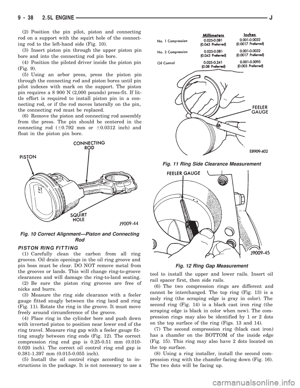
rod on a support with the squirt hole of the connect-
ing rod to the left-hand side (Fig. 10).
(3) Insert piston pin through the upper piston pin
bore and into the connecting rod pin bore.
(4) Position the piloted driver inside the piston pin
(Fig. 9).
(5) Using an arbor press, press the piston pin
through the connecting rod and piston bores until pin
pilot indexes with mark on the support. The piston
pin requires a 8 900 N (2,000 pounds) press-fit. If lit-
tle effort is required to install piston pin in a con-
necting rod, or if the rod moves laterally on the pin,
the connecting rod must be replaced.
(6) Remove the piston and connecting rod assembly
from the press. The pin should be centered in the
connecting rod (60.792 mm or60.0312 inch) and
float in the piston pin bore.
PISTON RING FITTING
(1) Carefully clean the carbon from all ring
grooves. Oil drain openings in the oil ring groove and
pin boss must be clear. DO NOT remove metal from
the grooves or lands. This will change ring-to-groove
clearances and will damage the ring-to-land seating.
(2) Be sure the piston ring grooves are free of
nicks and burrs.
(3) Measure the ring side clearance with a feeler
gauge fitted snugly between the ring land and ring
(Fig. 11). Rotate the ring in the groove. It must move
freely around circumference of the groove.
(4) Place ring in the cylinder bore and push down
with inverted piston to position near lower end of the
ring travel. Measure ring gap with a feeler gauge fit-
ting snugly between ring ends (Fig. 12). The correct
compression ring end gap is 0.25-0.51 mm (0.010-
0.020 inch). The correct oil control ring end gap is
0.381-1.397 mm (0.015-0.055 inch).
(5) Install the oil control rings according to in-
structions in the package. It is not necessary to use atool to install the upper and lower rails. Insert oil
rail spacer first, then side rails.
(6) The two compression rings are different and
cannot be interchanged. The top ring (Fig. 13) is a
moly ring (the scraping edge is gray in color). The
second ring (Fig. 14) is a black cast iron ring (the
scraping edge is black in color when new). The com-
pression rings may also be identified by 1 or 2 dots
on the top surface of the ring (Figs. 13 and 14).
(7) The second compression ring (black cast iron)
has a chamfer on the BOTTOM of the inside edge
(Fig. 15). This ring may also have 2 dots located on
the top surface.
(8) Using a ring installer, install the second com-
pression ring with the chamfer facing down (Fig. 16).
The two dots will be facing up.
Fig. 10 Correct AlignmentÐPiston and Connecting
Rod
Fig. 11 Ring Side Clearance Measurement
Fig. 12 Ring Gap Measurement
9 - 38 2.5L ENGINEJ
Page 907 of 1784

LEAK-DOWN TEST
After cleaning and inspection, test each tappet for
specified leak-down rate tolerance to ensure zero-lash
operation (Fig. 12).
Swing the weighted arm of the hydraulic valve tap-
pet tester away from the ram of the Leak-Down
Tester 7980.
(1) Place a 7.925-7.950 mm (0.312-0.313 inch) di-
ameter ball bearing on the plunger cap of the tappet.
(2) Lift the ram and position the tappet (with the
ball bearing) inside the tester cup.
(3) Lower the ram, then adjust the nose of the ram
until it contacts the ball bearing. DO NOT tighten
the hex nut on the ram.
(4) Fill the tester cup with hydraulic valve tappet
test oil until the tappet is completely submerged.
(5) Swing the weighted arm onto the push rod and
pump the tappet plunger up and down to remove air.
When the air bubbles cease, swing the weighted arm
away and allow the plunger to rise to the normal po-
sition.
(6) Adjust the nose of the ram to align the pointer
with the SET mark on the scale of the tester and
tighten the hex nut.
(7) Slowly swing the weighted arm onto the push
rod.
(8) Rotate the cup by turning the handle at the
base of the tester clockwise one revolution every 2
seconds.
(9) Observe the leak-down time interval from the
instant the pointer aligns with the START mark on
the scale until the pointer aligns with the 0.125
mark. A normally functioning tappet will require 20-
110 seconds to leak-down. Discard tappets with leak-
down time interval not within this specification.
INSTALLATION
It is not necessary to charge the tappets with en-
gine oil. They will charge themselves within a very
short period of engine operation.(1) Dip each tappet in Mopar Engine Oil Supple-
ment, or equivalent.
(2) Use Hydraulic Valve Tappet Removal/Installa-
tion Tool C-4129-A to install each tappet in the same
bore from where it was originally removed.
(3) Install the exhaust and intake manifolds (refer
to Group 11, Exhaust System and Intake Manifold
for the proper procedure).
(4) Install the engine cylinder head and gasket.
(5) Install the push rods in their original locations.
(6) Install the rocker arms and bridge and pivot
assemblies at their original locations. Loosely install
the capscrews at each bridge.
(7) Tighten the capscrews alternately, one turn at
a time, to avoid damaging the bridges. Tighten the
capscrews to 28 Nzm (21 ft. lbs.) torque.
(8) Pour the remaining Mopar Engine Oil Supple-
ment, or equivalent over the entire valve actuating
assembly. The Mopar Engine Oil Supplement, or
equivalent must remain with the engine oil for at
least 1 609 km (1,000 miles). The oil supplement
need not be drained until the next scheduled oil
change.
(9) Install the engine cylinder head cover.
VALVE TIMING
Disconnect the spark plug wires and remove the
spark plugs.
Remove the engine cylinder head cover.
Remove the capscrews, bridge and pivot assembly,
and rocker arms from above the No.1 cylinder.
Alternately loosen each capscrew, one turn at a
time, to avoid damaging the bridge.
Rotate the crankshaft until the No.6 piston is at
top dead center (TDC) on the compression stroke.
Rotate the crankshaft counterclockwise (viewed
from the front of the engine) 90É.
Install a dial indicator on the end of the No.1 cyl-
inder intake valve push rod. Use rubber tubing to se-
cure the indicator stem on the push rod.
Set the dial indicator pointer at zero.
Rotate the crankshaft clockwise (viewed from the
front of the engine) until the dial indicator pointer
indicates 0.305 mm (0.012 inch) travel distance (lift).
The timing notch index on the vibration damper
should be aligned with the TDC mark on the timing
degree scale.
If the timing notch is more than 13 mm (1/2 inch)
away from the TDC mark in either direction, the
valve timing is incorrect.
If the valve timing is incorrect, the cause may be a
broken camshaft pin. It is not necessary to replace
the camshaft because of pin failure. A spring pin is
available for service replacement.
Fig. 12 Leak-Down Tester 7980
9 - 66 4.0L ENGINEJ
Page 911 of 1784

(5) Remove the distributor cap and mark the posi-
tion of the rotor.
(6) Remove the distributor and ignition wires.
(7) Remove the engine cylinder head cover.
(8) Remove the rocker arms, bridges and pivots.
(9) Remove the push rods.
(10) Remove the engine cylinder head and gasket.
(11) Remove the hydraulic valve tappets from the
engine cylinder head.
(12) Remove the vibration damper.
(13) Remove the timing case cover.
(14) Remove the timing chain and sprockets.
(15) Remove the front bumper and/or grille, as re-
quired.
(16) Remove the camshaft (Fig. 9).
INSPECTION
Inspect the cam lobes for wear.
Inspect the bearing journals for uneven wear pat-
tern or finish.
Inspect the bearings for wear.
Inspect the distributor drive gear for wear.
If the camshaft appears to have been rubbing
against the timing case cover, examine the oil pres-
sure relief holes in the rear cam journal. The oil
pressure relief holes must be free of debris.
INSTALLATION
(1) Lubricate the camshaft with Mopar Engine Oil
Supplement, or equivalent.
(2) Carefully install the camshaft to prevent dam-
age to the camshaft bearings (Fig. 9).
(3) Install the timing chain, crankshaft sprocket
and camshaft sprocket with the timing marks
aligned.
(4) Install the camshaft sprocket retaining preload
bolt. Tighten the bolt to 108 Nzm (80 ft. lbs.) torque.
(5) Lubricate the tension spring, the thrust pin
and the pin bore in the preload bolt with Mopar En-
gine Oil Supplement, or equivalent. Install the
spring and thrust pin in the preload bolt head.(6) Install the timing case cover with a replace-
ment oil seal (Fig. 10). Refer to Timing Case Cover
Installation.
(7) Install the vibration damper (Fig. 10).
(8) Install the hydraulic valve tappets.
(9) Install the engine cylinder head.
(10) Install the push rods.
(11) Install the rocker arms and pivot and bridge
assemblies. Tighten each of the capscrews for each
bridge alternately, one turn at a time, to avoid dam-
aging the bridge.
(12) Install the engine cylinder head cover.
(13) Install the serpentine drive belt and tighten to
the specified tension (refer to Group 7, Cooling Sys-
tem for the proper procedure).
(14) Rotate the crankshaft until the No.1 piston is
at the TDC position on the compression stroke.
(15) Install the distributor, cap and ignition wires.
Install the distributor so that the rotor is aligned
with the mark made during removal. The rotor
should be aligned with the No.1 cylinder spark plug
terminal on the cap when the distributor housing is
fully seated on the cylinder block.
During installation, lubricate the hydraulic
valve tappets and all valve components with Mo-
par Engine Oil Supplement, or equivalent. The
Mopar Engine Oil Supplement, or equivalent
must remain with the engine oil for at least 1 609
km (1,000 miles). The oil supplement need not be
drained until the next scheduled oil change.
(16) Install the A/C condenser and receiver/drier
assembly, if equipped (refer to Group 24, Heating
and Air Conditioning).
CAUTION: Both service valves must be opened be-
fore the air conditioning system is operated.
(17) Install the radiator, connect the hoses and fill
the cooling system to the specified level (refer to
Group 7, Cooling System for the proper procedure).
Fig. 9 Camshaft
Fig. 10 Timing Case Cover Components
9 - 70 4.0L ENGINEJ
Page 919 of 1784
(6) Remove the piston and connecting rod assembly
from the press. The pin should be centered in the
connecting rod (60.792 mm or60.0312 inch) and
float in the piston pin bore.
PISTON RING FITTING
(1) Carefully clean the carbon from all ring
grooves. Oil drain openings in the oil ring groove and
pin boss must be clear. DO NOT remove metal from
the grooves or lands. This will change ring-to-groove
clearances and will damage the ring-to-land seating.
(2) Be sure the piston ring grooves are free of
nicks and burrs.
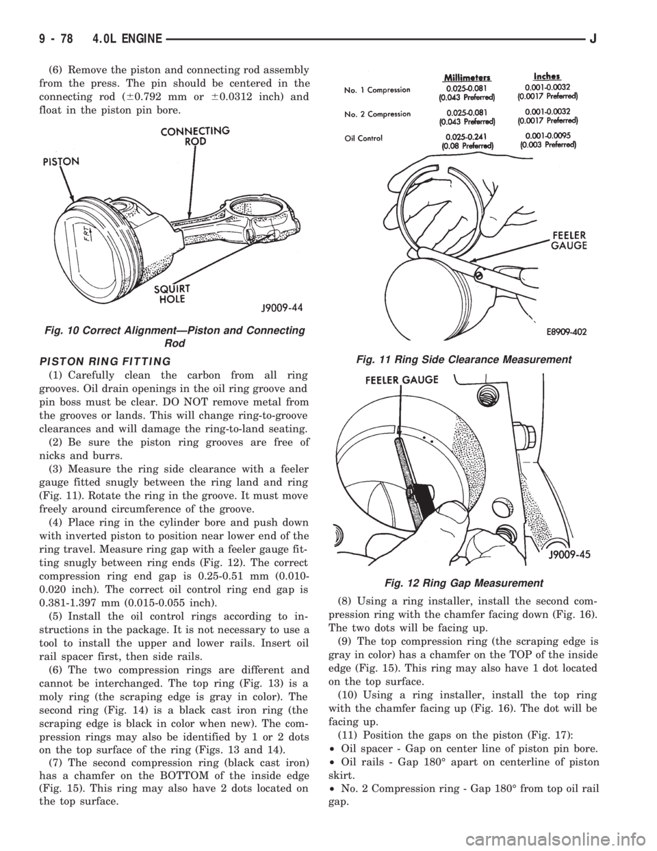
(3) Measure the ring side clearance with a feeler
gauge fitted snugly between the ring land and ring
(Fig. 11). Rotate the ring in the groove. It must move
freely around circumference of the groove.
(4) Place ring in the cylinder bore and push down
with inverted piston to position near lower end of the
ring travel. Measure ring gap with a feeler gauge fit-
ting snugly between ring ends (Fig. 12). The correct
compression ring end gap is 0.25-0.51 mm (0.010-
0.020 inch). The correct oil control ring end gap is
0.381-1.397 mm (0.015-0.055 inch).
(5) Install the oil control rings according to in-
structions in the package. It is not necessary to use a
tool to install the upper and lower rails. Insert oil
rail spacer first, then side rails.
(6) The two compression rings are different and
cannot be interchanged. The top ring (Fig. 13) is a
moly ring (the scraping edge is gray in color). The
second ring (Fig. 14) is a black cast iron ring (the
scraping edge is black in color when new). The com-
pression rings may also be identified by 1 or 2 dots
on the top surface of the ring (Figs. 13 and 14).
(7) The second compression ring (black cast iron)
has a chamfer on the BOTTOM of the inside edge
(Fig. 15). This ring may also have 2 dots located on
the top surface.(8) Using a ring installer, install the second com-
pression ring with the chamfer facing down (Fig. 16).
The two dots will be facing up.
(9) The top compression ring (the scraping edge is
gray in color) has a chamfer on the TOP of the inside
edge (Fig. 15). This ring may also have 1 dot located
on the top surface.
(10) Using a ring installer, install the top ring
with the chamfer facing up (Fig. 16). The dot will be
facing up.
(11) Position the gaps on the piston (Fig. 17):
²Oil spacer - Gap on center line of piston pin bore.
²Oil rails - Gap 180É apart on centerline of piston
skirt.
²No. 2 Compression ring - Gap 180É from top oil rail
gap.
Fig. 10 Correct AlignmentÐPiston and Connecting
Rod
Fig. 11 Ring Side Clearance Measurement
Fig. 12 Ring Gap Measurement
9 - 78 4.0L ENGINEJ
Page 985 of 1784
AIR CONDITIONING (A/C) CLUTCH RELAYÐPCM
OUTPUT
The powertrain control module (PCM) activates the
A/C compressor through the A/C clutch relay. The
PCM regulates A/C compressor operation by switch-
ing the ground circuit for the A/C clutch relay on
and off. The relay is located in the Power Distribu-
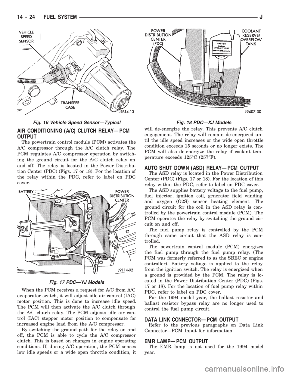
tion Center (PDC) (Figs. 17 or 18). For the location of
the relay within the PDC, refer to label on PDC
cover.
When the PCM receives a request for A/C from A/C
evaporator switch, it will adjust idle air control (IAC)
motor position. This is done to increase idle speed.
The PCM will then activate the A/C clutch through
the A/C clutch relay. The PCM adjusts idle air con-
trol (IAC) stepper motor position to compensate for
increased engine load from the A/C compressor.
By switching the ground path for the relay on and
off, the PCM is able to cycle the A/C compressor
clutch. This is based on changes in engine operating
conditions. If, during A/C operation, the PCM senses
low idle speeds or a wide open throttle condition, itwill de-energize the relay. This prevents A/C clutch
engagement. The relay will remain de-energized un-
til the idle speed increases or the wide open throttle
condition exceeds 15 seconds or no longer exists. The
PCM will also de-energize the relay if coolant tem-
perature exceeds 125ÉC (257ÉF).
AUTO SHUT DOWN (ASD) RELAYÐPCM OUTPUT
The ASD relay is located in the Power Distribution
Center (PDC) (Figs. 17 or 18). For the location of this
relay within the PDC, refer to label on PDC cover.
The ASD supplies battery voltage to the fuel pump,
fuel injector, ignition coil, generator field winding
and oxygen (O2S) sensor heating element. The
ground circuit for the coil in the ASD relay is con-
trolled by the powertrain control module (PCM). The
PCM operates the relay by switching the ground cir-
cuit on and off.
The fuel pump relay is controlled by the PCM
through same circuit that the ASD relay is con-
trolled.
The powertrain control module (PCM) energizes
the fuel pump through the fuel pump relay. (The
PCM was formerly referred to as the SBEC or engine
controller). Battery voltage is applied to the relay
from the ignition switch. The relay is energized when
a ground is provided by the PCM. The relay is lo-
cated in the Power Distribution Center (PDC) (Figs.
17 or 18). For the location of fuel pump relay within
PDC, refer to label on PDC cover.
For the 1994 model year, the ballast resistor and
ballast resistor bypass relay are no longer used to
control the fuel pump circuit.
DATA LINK CONNECTORÐPCM OUTPUT
Refer to the previous paragraphs on Data Link
ConnectorÐPCM Input for information.
EMR LAMPÐPCM OUTPUT
The EMR lamp is not used for the 1994 model
year.
Fig. 16 Vehicle Speed SensorÐTypical
Fig. 17 PDCÐYJ Models
Fig. 18 PDCÐXJ Models
14 - 24 FUEL SYSTEMJ
Page 1051 of 1784
STEERING LINKAGEÐXJ
INDEX
page page
Drag Link.............................. 14
Pitman Arm............................. 15
Service Information....................... 14Steering Dampener....................... 15
Tie Rod ................................ 14
SERVICE INFORMATION
The steering linkage consists of a pitman arm, drag
link, tie rod, and steering dampener. Adjustment
sleeves are used on the tie rod and drag link for toe
and steering wheel alignment.
Refer to Group 2, Front Suspension and Axle for
additional information.
The tie-rod end ball stud seals should be inspected
during all oil changes.
A damaged ball stud seal requires removal of the
seal. Inspect the tie-rod end ball stud at the throat
opening. Check for lubricant loss, contamination, ball
stud wear or corrosion. If these conditions exist, re-
place the tie-rod. A replacement seal can be installed
if lubricant is in good condition. Otherwise, a com-
plete replacement ball stud end should be installed.
Lubricate the tie-rod end with MOPARtMulti-Mile-
age Lubricant, or equivalent product.
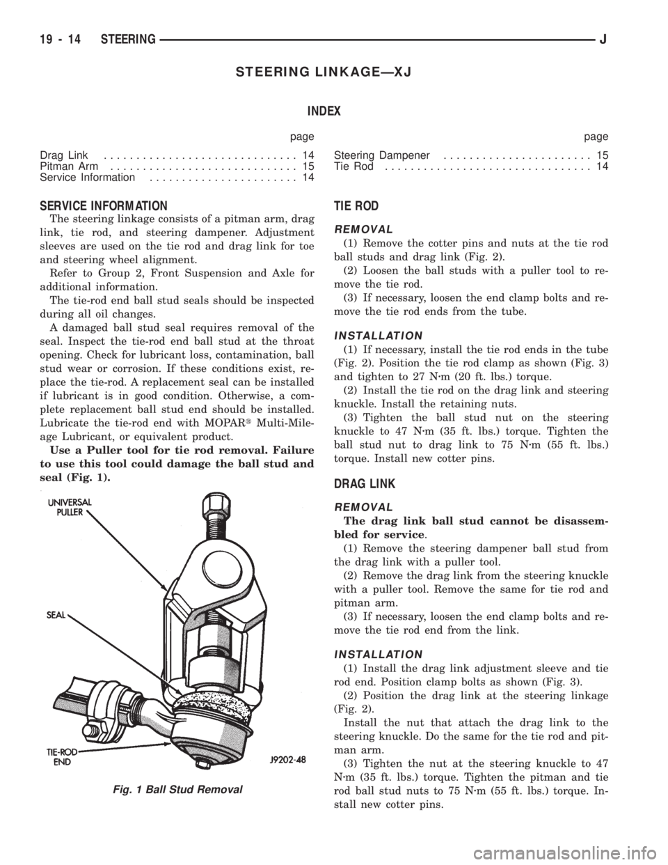
Use a Puller tool for tie rod removal. Failure
to use this tool could damage the ball stud and
seal (Fig. 1).
TIE ROD
REMOVAL
(1) Remove the cotter pins and nuts at the tie rod
ball studs and drag link (Fig. 2).
(2) Loosen the ball studs with a puller tool to re-
move the tie rod.
(3) If necessary, loosen the end clamp bolts and re-
move the tie rod ends from the tube.
INSTALLATION
(1) If necessary, install the tie rod ends in the tube
(Fig. 2). Position the tie rod clamp as shown (Fig. 3)
and tighten to 27 Nzm (20 ft. lbs.) torque.
(2) Install the tie rod on the drag link and steering
knuckle. Install the retaining nuts.
(3) Tighten the ball stud nut on the steering
knuckle to 47 Nzm (35 ft. lbs.) torque. Tighten the
ball stud nut to drag link to 75 Nzm (55 ft. lbs.)
torque. Install new cotter pins.
DRAG LINK
REMOVAL
The drag link ball stud cannot be disassem-
bled for service.
(1) Remove the steering dampener ball stud from
the drag link with a puller tool.
(2) Remove the drag link from the steering knuckle
with a puller tool. Remove the same for tie rod and
pitman arm.
(3) If necessary, loosen the end clamp bolts and re-
move the tie rod end from the link.
INSTALLATION
(1) Install the drag link adjustment sleeve and tie
rod end. Position clamp bolts as shown (Fig. 3).
(2) Position the drag link at the steering linkage
(Fig. 2).
Install the nut that attach the drag link to the
steering knuckle. Do the same for the tie rod and pit-
man arm.
(3) Tighten the nut at the steering knuckle to 47
Nzm (35 ft. lbs.) torque. Tighten the pitman and tie
rod ball stud nuts to 75 Nzm (55 ft. lbs.) torque. In-
stall new cotter pins.
Fig. 1 Ball Stud Removal
19 - 14 STEERINGJ
Page 1054 of 1784
STEERING LINKAGEÐYJ
INDEX
page page
Drag Link.............................. 17
Pitman Arm............................. 18
Service Information....................... 17Steering Dampener....................... 18
Tie Rod ................................ 17
SERVICE INFORMATION
The steering linkage consists of a pitman arm, drag
link, tie rod, and steering dampener. Adjustment
sleeves are used on the tie rod and drag link for toe
and steering wheel alignment.
Refer to Group 2, Front Suspension and Axle for
additional information.
The tie-rod end ball stud seals should be inspected
during all oil changes.
A damaged ball stud seal requires removal of the
seal. Inspect the tie-rod end ball stud at the throat
opening. Check for lubricant loss, contamination, ball
stud wear or corrosion. If these conditions exist, re-
place the tie-rod. A replacement seal can be installed
if lubricant is in good condition. Otherwise, a com-
plete replacement ball stud end should be installed.
Lubricate the tie-rod end with MOPARtMulti-Mile-
age Lubricant, or equivalent product.
Use a Puller tool for tie rod removal. Failure
to use this tool could damage the ball stud and
seal (Fig. 1).
TIE ROD
REMOVAL
(1) Remove the cotter pins and nuts at the steering
knuckles and drag link (Fig. 2). Remove the steering
dampener from the tie rod.
(2) Loosen the ball studs with a puller tool to re-
move the tie rod.
(3) If necessary, loosen the end clamp bolts and re-
move the tie rod end from the tube.
INSTALLATION
(1) If necessary, install the tie rod end in the tube
(Fig. 2). Position the tie rod clamp as shown (Fig. 3).
Tighten the ball-stud end clamp bolts to 49 Nzm (36
ft. lbs.) torque.
(2) Install the tie rod on the drag link and steering
knuckles. Install the retaining nuts. Install the steer-
ing dampener to the tie rod.
(3) Tighten the ball stud nut on the steering
knuckle to 47 Nzm (35 ft. lbs.) torque. Tighten the
ball stud nut to drag link to 75 Nzm (55 ft. lbs.)
torque. Tighten the steering dampener nut to 74 Nzm
(55 ft. lbs.) torque. Install new cotter pins.
DRAG LINK
REMOVAL
(1) Remove the cotter pins and nuts at the tie rod
and pitman arm (Fig. 2).
(2) Remove the drag link from the tie rod and pit-
man arm with a puller tool.
(3) If necessary, loosen the end clamp bolts and re-
move the tie rod ends from the tube.
INSTALLATION
(1) Install the drag link adjustment sleeve and tie
rod ends. Position clamp bolts as shown (Fig. 3).
(2) Position the drag link at the steering linkage
(Fig. 2).
Install the drag link to tie rod and pitman arm.
(3) Tighten the nut at the pitman arm to 74 Nzm
(55 ft. lbs.) torque. Tighten the tie rod ball stud nut
to 75 Nzm (55 ft. lbs.) torque. Install new cotter pins.
Fig. 1 Ball Stud Removal
JSTEERING 19 - 17
Page 1177 of 1784
30RH/32RH AUTOMATIC TRANSMISSION
INDEX
page page
General Information....................... 66
Parts Interchangeability.................... 66
Recommended Fluid...................... 66
Specifications and Band Adjustments......... 66Torque Converter........................ 66
Transmission Application................... 66
Transmission Controls and Components....... 66
Transmission Identification.................. 66
GENERAL INFORMATION
TRANSMISSION APPLICATION
Chrysler 30RH and 32RH automatic transmissions
are used in XJ/YJ models. Both transmissions are
three speed, automatics with a gear-type oil pump,
two clutches and bands and a planetary gear system
(Fig. 1). The 30RH is used with 2.5L engines and the
32RH is used with 4.0L engines.
TORQUE CONVERTER
A three element, torque converter is used for all
applications. The converter consists of the impeller,
stator, and turbine.
The converter used with all 30RH/32RH transmis-
sions is equipped with a converter clutch. The clutch
is engaged by an electrical solenoid and mechanical
clutch module on the valve body. The solenoid is op-
erated by the powertrain control module.
The impeller is connected to the engine crankshaft
through the front cover which is welded to the impel-
ler. The turbine is splined to the transmission input
shaft and the stator is splined to the transmission re-
action shaft.
The torque converter is a welded assembly and is
not a repairable component. The converter is serviced
as an assembly.
RECOMMENDED FLUID
The recommended (and preferred) fluid for 30RH/
32RH transmissions is Mopar ATF Plus, Type 7176.
Mopar Dexron II can be used but only if ATF Plus
is not available.
Transmission fluid capacity is approximately 17
pints (7.9 liters). This is the approximate amount of
fluid required to fill the transmission and torque con-
verter after overhaul.
TRANSMISSION IDENTIFICATION
The transmission identification numbers are
stamped on the left side of the case just above the oil
pan gasket surface (Fig. 2). The first set of numbers
is the transmission part number. The next set of code
numbers set is the date of build. The final set of code
numbers represents the transmission serial number.
SPECIFICATIONS AND BAND ADJUSTMENTS
Service specifications and torque values are located
at the end of this group. Refer to the specifications
during service operations.
The band adjustment specifications for 1994
transmissions are different. Refer to the front
and rear band adjustment procedures in the In-
Vehicle Service section for details.
PARTS INTERCHANGEABILITY
The 1994 version of the 30RH (A904) transmission
is similar to previous models in appearance only. The
current 30RH is quite different and interchanging
new/old parts is definitely not recommended. Differ-
ent component dimensions, fluid passages, input/out-
put shafts, cases, bands, valve bodies and governor
assemblies are just a few of the changed items. The
32RH transmission is also different from previous
models and the same recommendations apply here as
well.
CAUTION: On YJ models with a 2.5L engine and
30RH transmission, special bolts are used to attach
the driveplate to the crankshaft. These bolts have a
smaller hex head for torque converter clearance.
DO NOT interchange these bolts with similar size
bolts for any reason.
TRANSMISSION CONTROLS AND COMPONENTS
The transmission hydraulic control system per-
forms five basic functions, which are:
²pressure supply
²pressure regulation
²flow control
²clutch/band apply and release
²lubrication
Pressure Supply And Regulation
The oil pump generates the fluid working pressure
needed for operation and lubrication. The pump is
driven by the torque converter. The converter is con-
nected to the engine crankshaft through the drive-
plate.
The pressure regulator valve maintains operating
(line) pressure. The regulator valve is located in the
valve body. The amount of line pressure developed is
21 - 66 30RH/32RH AUTOMATIC TRANSMISSIONJ