1994 JEEP CHEROKEE oil change
[x] Cancel search: oil changePage 1207 of 1784
30RH/32RH IN-VEHICLE SERVICE
INDEX
page page
Checking Fluid Level and Condition........... 96
Front Band Adjustment.................... 99
Gearshift Linkage Adjustment (YJ)............ 96
Governor and Park Gear Service............ 101
Oil Filter Replacement.................... 100
Park Interlock Cable Adjustment (XJ)......... 97
Park Lock Component Replacement......... 102
Park/Neutral Position Switch Service......... 103
Rear Band Adjustment.................... 99
Recommended Fluid...................... 96
Servicing Transmission Cooler Lines and Fittings. 106
Shift Cable Adjustment (XJ)................ 97
Speedometer Service.................... 103
Transmission Cooler Flow Testing........... 106
Transmission Cooler Reverse Flushing....... 105
Transmission Throttle Cable Adjustment (XJ/YJ) . 98
Valve Body Installation................... 101
Valve Body Removal..................... 100
Valve Body Service...................... 100
RECOMMENDED FLUID
The recommended and preferred fluid for 30RH/
32RH transmissions is Mopar ATF Plus, Type 7176.
Mopar Dexron II is acceptable but should only be
used when ATF Plus is not available.
Transmission fluid capacity is approximately 17
pints (7.9 liters). This is the approximate amount of
fluid required to fill the transmission and torque con-
verter after overhaul.
CHECKING FLUID LEVEL AND CONDITION
(1) Position vehicle on flat, level surface. This is
important in obtaining an accurate fluid level check.
(2) To avoid false readings, which could produce
under or over fill condition, do not check level until
fluid is at normal operating temperature.
(3) Shift transmission into Neutral.
(4) Apply parking brakes.
(5) Operate engine at curb idle speed.
WARNING: WHEN PERFORMING UNDERHOOD OP-
ERATIONS WITH THE ENGINE RUNNING, KEEP
YOUR HANDS WELL AWAY FROM HOT OR ROTAT-
ING ENGINE COMPONENTS. DO NOT WEAR
LOOSE ARTICLES OF CLOTHING WHICH COULD
BECOME ENTANGLED IN ENGINE COMPONENTS
OR ACCESSORIES.
(6) Shift transmission through all gear ranges and
back to Neutral (leave engine running).
(7) Clean exterior of dipstick cap and fill tube be-
fore removing transmission dipstick.
(8) Remove dipstick and inspect fluid level.
²Correct level is to FULL mark
²Acceptable level is between ADD and FULL marks
(9) Check fluid condition. Fluid should be dark to
light red in color and free of dirt or debris.
(10) If fluid is discolored or smells burned but
transmission operation was OK, check cooler flow,
flush cooler and lines and change fluid and filter.
Then road test again to confirm proper operation.(11) If fluid is black or dark brown, burned/turned
to sludge, contains large quantities of metal or fric-
tion material particles, transmission will need over-
haul. Especially if problems were evident during
road test and preliminary diagnosis. Fluid cooler
should also be flow tested and flushed if necessary.
GEARSHIFT LINKAGE ADJUSTMENT (YJ)
(1) Check linkage adjustment by starting engine in
Park and Neutral.
(2) Adjustment is OK if engine starts only in park
and Neutral. Adjustment is incorrect if engine starts
in one but not both positions.
(3) If engine starts in any position other than Park
or Neutral, or if engine will not start at all, park/
neutral position switch may be faulty.
(4) Shift transmission into Park.
(5) Raise vehicle.
(6) Check condition of shift rods, bellcrank, bell-
crank brackets and linkage bushings/grommets (Fig.
1). Tighten, repair, replace worn, damaged parts. Do
not attempt adjustment if linkage components are
worn or damaged.
(7) Loosen shift rod trunnion lock bolt or nut. Be
sure upper shift rod slides freely in trunnion (Fig. 1).
Also be sure shift rods and bellcrank rotate freely
and do not bind at any point.
(8) Verify that manual lever is in Park detent
(Fig. 1). Move lever all the way rearward to be sure
it is in Park.
(9) Check for positive engagement of park lock by
attempting to rotate propeller shaft. Shaft will not
turn when park pawl is engaged.
(10) Adjust shift rod trunnion to a obtain free pin
fit in bellcrank arm and tighten trunnion lock bolt or
nut. Prevent shift rod from turning while tightening
bolt or nut. Gearshift linkage lash must be elimi-
nated to obtain proper adjustment. Eliminate lash by
pulling downward on shift rod and pressing upward
on bellcrank.
21 - 96 30RH/32RH IN-VEHICLE SERVICEJ
Page 1217 of 1784
condenser. The auxiliary cooler is a serviceable com-
ponent and can be repaired if necessary.
The main and auxiliary coolers should be thor-
oughly reverse flushed if a transmission failure
contaminates the fluid. Reverse flushing the cooler
and lines will prevent sludge and particles from
flowing back into the transmission after repair.
The same flushing procedure is used for main and
auxiliary coolers. Pressure equipment is preferred for
reverse flushing. However, reverse flushing can be
performed using hand operated equipment as de-
scribed in the following procedure.
REVERSE FLUSHING PROCEDURE
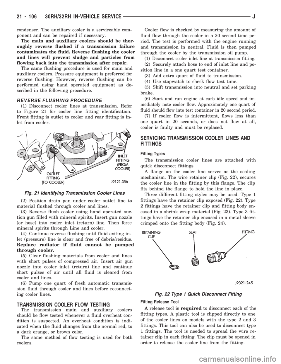
(1) Disconnect cooler lines at transmission. Refer
to Figure 21 for cooler line fitting identification.
Front fitting is outlet to cooler and rear fitting is in-
let from cooler.
(2) Position drain pan under cooler outlet line to
material flushed through cooler and lines.
(3) Reverse flush cooler using hand operated suc-
tion gun filled with mineral spirits. Insert gun nozzle
(or hose) into cooler inlet (return) line. Then force
mineral spirits through Line and cooler.
(4) Continue reverse flushing until fluid exiting in-
let (pressure) line is clear and free of debris/residue.
Replace radiator if fluid cannot be pumped
through cooler.
(5) Clear flushing materials from cooler and lines
with short pulses of compressed air. Insert air gun
nozzle into cooler inlet (return) line and continue
short pulses of air until all fluid is cleared from
cooler and lines.
(6) Pump one quart of fresh automatic transmis-
sion fluid through cooler and lines before reconnect-
ing cooler lines.
TRANSMISSION COOLER FLOW TESTING
The transmission main and auxiliary coolers
should be flow tested whenever a fluid overheat con-
dition is suspected. An overheat condition is indi-
cated when the fluid changes from the normal red, to
a dark orange, or brown color.
The same method of flow testing is used for both
coolers.Cooler flow is checked by measuring the amount of
fluid flow through the cooler in a 20 second time pe-
riod. The test is performed with the engine running
and transmission in neutral. Fluid is then pumped
through the cooler by the transmission oil pump.
(1) Disconnect cooler inlet line at transmission fitting.
(2) Securely attach hose to end of inlet line and po-
sition line in a one quart test container.
(3) Add extra quart of fluid to transmission.
(4) Use stopwatch to check flow test time.
(5) Shift transmission into neutral and set parking
brake.
(6) Start and run engine at curb idle speed and im-
mediately note cooler flow. Approximately one quart of
fluid should flow into test container in 20 second period.
(7) If cooler flow is intermittent, flows less than
one quart in 20 seconds, or does not flow at all,
cooler is faulty and must be replaced.
SERVICING TRANSMISSION COOLER LINES AND
FITTINGS
Fitting Types
The transmission cooler lines are attached with
quick disconnect fittings.
A flange on the cooler line serves as the sealing
mechanism. The wire retainer clip (Fig. 22), secures
the cooler line in the fitting by this flange. The clip
fits behind the flange to hold the line in place.
Three different fitting styles may be used. Type 1
fittings have the retainer clip exposed (Fig. 22). Type
2 fittings have the retainer clip and fitting body en-
cased in a shrink wrap material (Fig. 23). Type 3 fit-
tings have the retainer clip encased in a metal sleeve
crimped onto the fitting body (Fig. 24).
Fitting Release Tool
A release tool isrequiredto disconnect each of the
fitting types. A plastic tool is clipped directly to one
of the cooler lines on models with the type 2 and 3
fittings. This tool can also be used to disconnect type
1 fittings. The tool is needed to spread the wire re-
tainer clip in each fitting. The clip must be opened in
order to release the cooler line from the fitting.
Fig. 21 Identifying Transmission Cooler Lines
Fig. 22 Type 1 Quick Disconnect Fitting
21 - 106 30RH/32RH IN-VEHICLE SERVICEJ
Page 1220 of 1784
CONVERTERÐPUMP SEALÐDRIVE PLATE SERVICE
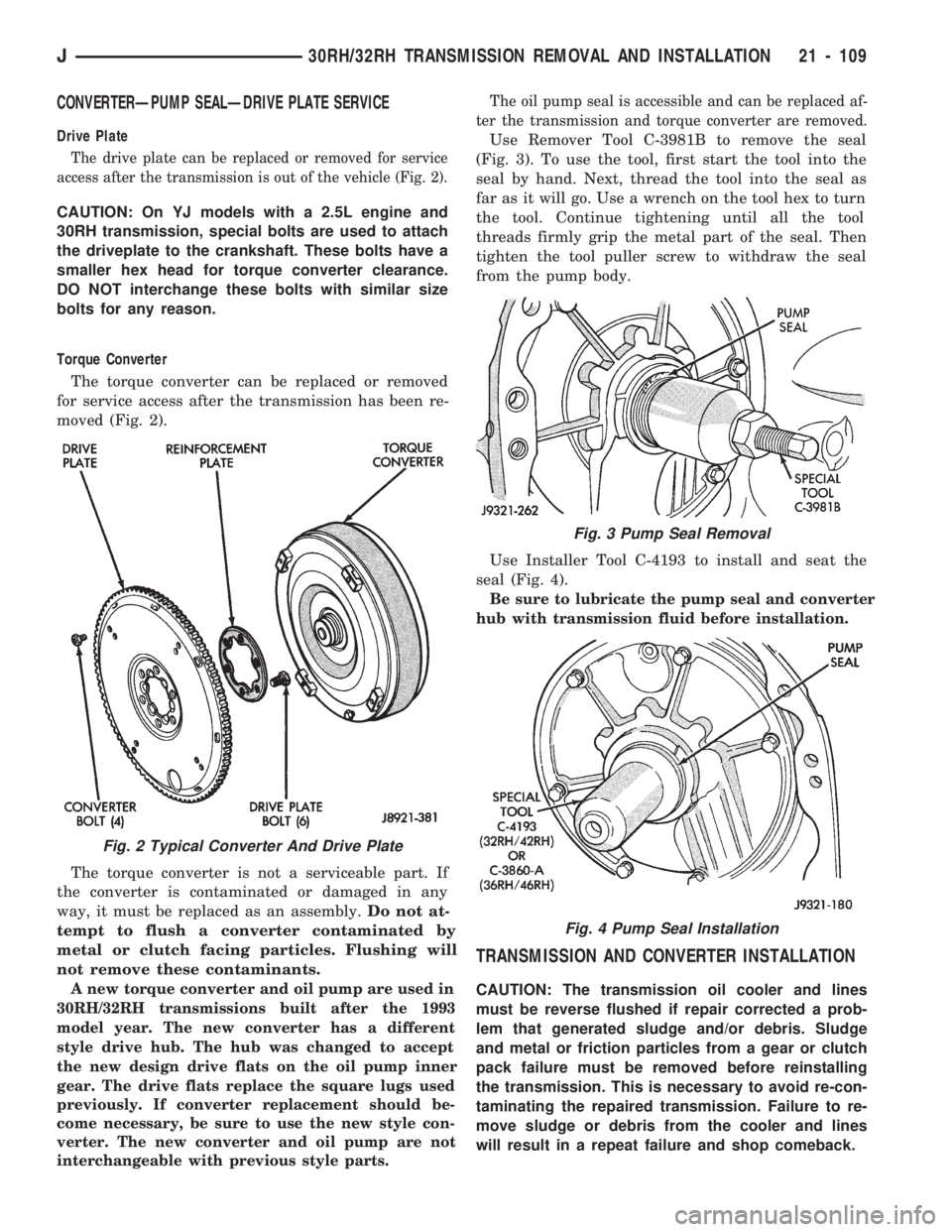
Drive Plate
The drive plate can be replaced or removed for service
access after the transmission is out of the vehicle (Fig. 2).
CAUTION: On YJ models with a 2.5L engine and
30RH transmission, special bolts are used to attach
the driveplate to the crankshaft. These bolts have a
smaller hex head for torque converter clearance.
DO NOT interchange these bolts with similar size
bolts for any reason.
Torque Converter
The torque converter can be replaced or removed
for service access after the transmission has been re-
moved (Fig. 2).
The torque converter is not a serviceable part. If
the converter is contaminated or damaged in any
way, it must be replaced as an assembly.Do not at-
tempt to flush a converter contaminated by
metal or clutch facing particles. Flushing will
not remove these contaminants.
A new torque converter and oil pump are used in
30RH/32RH transmissions built after the 1993
model year. The new converter has a different
style drive hub. The hub was changed to accept
the new design drive flats on the oil pump inner
gear. The drive flats replace the square lugs used
previously. If converter replacement should be-
come necessary, be sure to use the new style con-
verter. The new converter and oil pump are not
interchangeable with previous style parts.The oil pump seal is accessible and can be replaced af-
ter the transmission and torque converter are removed.
Use Remover Tool C-3981B to remove the seal
(Fig. 3). To use the tool, first start the tool into the
seal by hand. Next, thread the tool into the seal as
far as it will go. Use a wrench on the tool hex to turn
the tool. Continue tightening until all the tool
threads firmly grip the metal part of the seal. Then
tighten the tool puller screw to withdraw the seal
from the pump body.
Use Installer Tool C-4193 to install and seat the
seal (Fig. 4).
Be sure to lubricate the pump seal and converter
hub with transmission fluid before installation.
TRANSMISSION AND CONVERTER INSTALLATION
CAUTION: The transmission oil cooler and lines
must be reverse flushed if repair corrected a prob-
lem that generated sludge and/or debris. Sludge
and metal or friction particles from a gear or clutch
pack failure must be removed before reinstalling
the transmission. This is necessary to avoid re-con-
taminating the repaired transmission. Failure to re-
move sludge or debris from the cooler and lines
will result in a repeat failure and shop comeback.
Fig. 2 Typical Converter And Drive Plate
Fig. 3 Pump Seal Removal
Fig. 4 Pump Seal Installation
J30RH/32RH TRANSMISSION REMOVAL AND INSTALLATION 21 - 109
Page 1253 of 1784
Inspect the valves and plugs for scratches, burrs,
nicks, or scores. Also inspect the coating on the alu-
minum valves and plugs (Fig. 114). If the coating is
damaged or worn through, the valve (or valve body)
should be replaced.
Aluminum valves and plugs should not be sanded
or polished under any circumstances. However, mi-
nor burrs or scratches on steel valves and plugs can
be removed with crocus cloth but do not round off the
valve or plug edges. Squareness of these edges is vi-
tally important. These edges prevent foreign matter
from lodging between the valves, plugs and bore.
Inspect all the valve and plug bores in the valve
body. Use a penlight to view the bore interiors. Re-place the valve body if any bores are distorted or
scored. Inspect all of the valve body springs. The
springs must be free of distortion, warpage or broken
coils.
Trial fit each valve and plug in its bore to check
freedom of operation. When clean and dry, the valves
and plugs should drop freely into the bores. Valve
body bores do not change dimensionally with use. If
the valve body functioned correctly when new, it will
continue to operate properly after cleaning and in-
spection. It should not be necessary to replace a
valve body assembly unless it is damaged in han-
dling.
21 - 142 30RH/32RH TRANSMISSION OVERHAULJ
Page 1265 of 1784
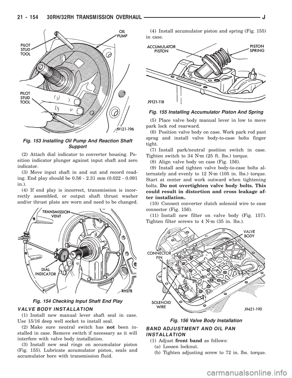
(2) Attach dial indicator to converter housing. Po-
sition indicator plunger against input shaft and zero
indicator.
(3) Move input shaft in and out and record read-
ing. End play should be 0.56 - 2.31 mm (0.022 - 0.091
in.).
(4) If end play is incorrect, transmission is incor-
rectly assembled, or output shaft thrust washer
and/or thrust plate are worn and need to be changed.
VALVE BODY INSTALLATION
(1) Install new manual lever shaft seal in case.
Use 15/16 deep well socket to install seal.
(2) Make sure neutral switch hasnotbeen in-
stalled in case. Remove switch if necessary as it will
interfere with valve body installation.
(3) Install new seal rings on accumulator piston
(Fig. 155). Lubricate accumulator piston, seals and
accumulator bore with transmission fluid.(4) Install accumulator piston and spring (Fig. 155)
in case.
(5) Place valve body manual lever in low to move
park lock rod rearward.
(6) Position valve body on case. Work park rod past
sprag and install valve body-to-case bolts finger
tight.
(7) Install park/neutral position switch in case.
Tighten switch to 34 Nzm (25 ft. lbs.) torque.
(8) Align valve body on case (Fig. 156).
(9) Install and tighten valve body-to-case bolts al-
ternately and evenly to 12 Nzm (105 in. lbs.) torque.
Start at center and work outward when tightening
bolts.Do not overtighten valve body bolts. This
could result in distortion and cross leakage af-
ter installation..
(10) Connect converter clutch solenoid wire to case
connector (Fig. 156).
(11) Install new filter on valve body (Fig. 157).
Tighten filter screws to 4 Nzm (35 in. lbs.).
BAND ADJUSTMENT AND OIL PAN
INSTALLATION
(1) Adjustfront bandas follows:
(a) Loosen locknut.
(b) Tighten adjusting screw to 72 in. lbs. torque.
Fig. 153 Installing Oil Pump And Reaction Shaft
Support
Fig. 154 Checking Input Shaft End Play
Fig. 155 Installing Accumulator Piston And Spring
Fig. 156 Valve Body Installation
21 - 154 30RH/32RH TRANSMISSION OVERHAULJ
Page 1683 of 1784
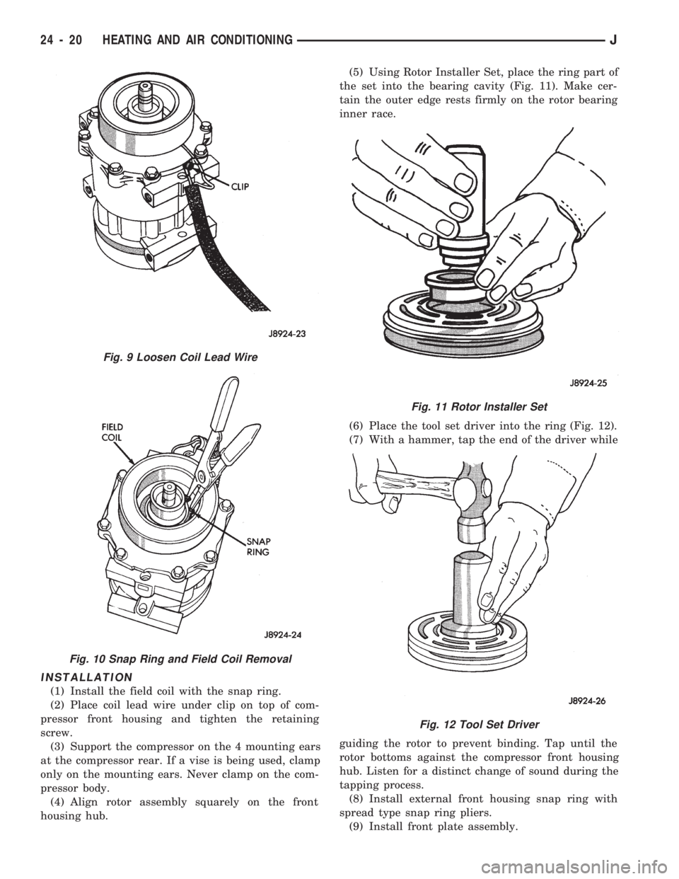
INSTALLATION
(1) Install the field coil with the snap ring.
(2) Place coil lead wire under clip on top of com-
pressor front housing and tighten the retaining
screw.
(3) Support the compressor on the 4 mounting ears
at the compressor rear. If a vise is being used, clamp
only on the mounting ears. Never clamp on the com-
pressor body.
(4) Align rotor assembly squarely on the front
housing hub.(5) Using Rotor Installer Set, place the ring part of
the set into the bearing cavity (Fig. 11). Make cer-
tain the outer edge rests firmly on the rotor bearing
inner race.
(6) Place the tool set driver into the ring (Fig. 12).
(7) With a hammer, tap the end of the driver while
guiding the rotor to prevent binding. Tap until the
rotor bottoms against the compressor front housing
hub. Listen for a distinct change of sound during the
tapping process.
(8) Install external front housing snap ring with
spread type snap ring pliers.
(9) Install front plate assembly.
Fig. 9 Loosen Coil Lead Wire
Fig. 10 Snap Ring and Field Coil Removal
Fig. 11 Rotor Installer Set
Fig. 12 Tool Set Driver
24 - 20 HEATING AND AIR CONDITIONINGJ
Page 1748 of 1784
CARPET/FLOOR MATS.................23-198
CARPET/MATÐXJ VEHICLES, FRONT.....23-129
CARPET/MATÐXJ VEHICLES, REAR......23-130
CARPETS AND FLOOR MATS............23-129
CARRIER, EXTERNAL SPARE/WHEEL
TIRE..............................23-172
CASE ASSEMBLY, TRANSFER......21-282,21-306
CASE CLEANING AND INSPECTION,
TRANSMISSION.....................21-118
CASE COVER OIL SEAL REPLACEMENT,
TIMING.........................9-26,9-67
CASE COVER, TIMING...............9-27,9-67
CASE DISASSEMBLY AND OVERHAUL,
TRANSFER...................21-277,21-297
CASE FILL LEVEL, TRANSFER...........21-294
CASE IDENTIFICATION, ENGINE AND
TRANSMISSION/TRANSFER..........INTRO.-3
CASE IDENTIFICATION, TRANSFER . 21-273,21-293
CASE INSTALLATION, TRANSFER . . . 21-276,21-296
CASE, LEGEND FOR NP231 TRANSFER....21-292
CASE, LEGEND FOR NP242 TRANSFER....21-319
CASE LUBRICANT, TRANSFER.....21-273,21-294
CASE, NP231 TRANSFER.........21-272,21-291
CASE, NP242 TRANSFER...............21-293
CASE OVERHAUL, FIRST-REVERSE
BRAKE PISTON AND TRANSMISSION....21-237
CASE REMOVAL, TRANSFER......21-276,21-296
CASE SPECIFICATIONS, TRANSMISSION/
TRANSFER.........................21-320
CASE, TRANSFER.......................0-25
CATALYTIC CONVERTER..............11-1,11-5
CATALYTIC CONVERTER/MUFFLER/
TAILPIPE SUPPORT BRACKETS.........23-85
CAUSES, CLUTCH PROBLEM...............6-3
CENTER HIGH MOUNTED STOP LAMP
(CHMSL)ÐXJ.......................8L-10
CENTER HIGH MOUNTED STOP LAMP
(CHMSL)ÐYJ.......................8L-11
CERTIFICATION LABEL, VEHICLE SAFETY . INTRO.-1
CHAIN AND SPROCKETS, TIMING......9-28,9-68
CHANGE AND FILTER REPLACEMENT,
ENGINE OIL..........................0-15
CHANGE, LUBRICANT; FRONT
SUSPENSION AND AXLE................2-22
CHANGE, LUBRICANT; REAR SUSPENSION
AND AXLES......................3-13,3-30
CHARGE RATE.........................8A-6
CHARGE, SYSTEM......................24-5
CHARGING, BATTERY....................8A-5
CHARGING TIME TABLE, BATTERY.........8A-5
CHASSIS AND BODY COMPONENTS........0-30
CHASSIS COMPONENT AND WHEEL
BEARING LUBRICANTS.................0-30
CHECK BALL DIMENSIONS, AW-4 VALVE
BODY.............................21-328
CHECK ENGINE LAMP FOR DIAGNOSTIC
TROUBLE CODES, INDICATOR..........8A-19
CHECK ENGINE, MALFUNCTION
INDICATOR LAMP; INSTRUMENT PANEL
AND GAUGESÐXJ................8E-2,8E-4
CHECK ENGINE, MALFUNCTION
INDICATOR LAMP; INSTRUMENT PANEL
AND GAUGESÐYJ...................8E-16
CHECK, PRELIMINARY BRAKE..............5-7
CHECK (ROAD TEST), OPERATIONAL.......8H-7
CHECK VALVE REPLACEMENT............19-33
CHECK VALVE TEST, POWER BOOSTER......5-11
CHECK WITH BATTERY INDICATOR
(BASE CLUSTER ONLY), OPERATIONAL . . . 8A-14
CHECK WITH VOLTMETER, OPERATIONAL . . . 8A-15
CHECKING FLUID LEVEL AND
CONDITION...................21-96,21-173
CHECKING FOR DIAGNOSTIC TROUBLE
CODE...............................8H-5
CHECKS FIRST, SYMPTOM AND ACTIONÐ
SEE PRELIMINARY.....................7-6
CHECKS, PRELIMINARY...................7-5
CHIP PROTECTION, STONE.............23-201
CHMSLÐXJ, CENTER HIGH MOUNTED
STOP LAMP.........................8L-10
CHMSLÐYJ, CENTER HIGH MOUNTED
STOP LAMP
.........................8L-11
CIRCUIT DIAGNOSIS, IGNITION
SECONDARY
........................8D-12
CIRCUIT IDENTIFICATION
................8W-2
CIRCUIT, PRINTED
.....................8E-22CIRCUIT REMOVAL, PRINTED............8E-24
CIRCUIT REPLACEMENT, PRINTED........8E-19
CIRCUIT REPLACEMENTÐINSTRUMENT
CLUSTER REMOVED, PRINTED...........8E-6
CIRCUIT SENSEÐPCM INPUT, IGNITION....14-21
CIRCUIT TESTS - (VOLTAGE DROP
METHOD), STARTER FEED..............8A-9
CIRCUIT TESTS, STARTER CONTROL......8A-11
CIRCUIT VOLTAGE, BATTERY OPEN.........8A-4
CIRCUIT VOLTAGE TEST, BATTERY OPEN....8A-3
CIRCUITS, ABS SYSTEM WIRING AND
ELECTRICAL..........................5-4
CLAMPS, FUEL TUBES/LINES/HOSES . . 14-9,14-56
CLASSIFICATION OF LUBRICANTS...........0-2
CLASSIFICATIONS AND RATINGS,
BATTERY............................8A-8
CLASSIFICATIONS AND RATINGSÐ
LEFT HAND DRIVE, BATTERY...........8B-10
CLASSIFICATIONS AND RATINGSÐ
RIGHT HAND DRIVE, BATTERY..........8B-10
CLEAN BRAKE FLUID, IMPORTANCE OF.....5-48
CLEANER, AIR.........................25-7
CLEANER FILTER ELEMENT, ENGINE AIR....0-16
CLEANER HOUSING, AIR; EMISSION
CONTROL SYSTEMS...................25-8
CLEANER HOUSING, AIR; FUEL SYSTEM....14-54
CLEANING AND INSPECTION . 21-13,21-204,21-305
CLEANING AND INSPECTION, CALIPER......5-28
CLEANING AND INSPECTION, GEAR.......19-40
CLEANING AND INSPECTION,
TRANSMISSION CASE................21-118
CLEANING OF TIRES....................22-2
CLEANING/INSPECTION; FRONT
SUSPENSION AND AXLE................2-35
CLEANING/INSPECTION; REAR
SUSPENSION AND AXLES...............3-18
CLEANING/REVERSE FLUSHING,
COOLING SYSTEM....................7-17
CLEARANCE, AW-4 BUSHING AND
PISTON...........................21-326
CLIMATE CONTROL SYSTEMÐXJ VEHICLES . 24-22
CLIMATE CONTROL SYSTEMÐYJ VEHICLES . 24-37
CLIP, FUEL AND BRAKE FLUID TUBE
RETAINER; BODY COMPONENTSÐXJ
VEHICLES..........................23-86
CLIP, FUEL AND BRAKE FLUID TUBE
RETAINER; FRAME AND BUMPERS.......13-16
CLUSTER AND GAUGE HOUSINGS,
INSTRUMENT......................23-190
CLUSTER BEZEL, INSTRUMENT.....23-91,23-191
CLUSTER BULB REPLACEMENT,
INSTRUMENT.......................8E-19
CLUSTER DIAGNOSIS, INSTRUMENT;
INSTRUMENT PANEL AND
GAUGESÐXJ.........................8E-3
CLUSTER DIAGNOSIS, INSTRUMENT;
INSTRUMENT PANEL AND GAUGESÐYJ . . 8E-14
CLUSTER GAUGES, INSTRUMENT;
INSTRUMENT PANEL AND GAUGESÐXJ . . 8E-13
CLUSTER GAUGES, INSTRUMENT;
INSTRUMENT PANEL AND GAUGESÐYJ . . 8E-27
CLUSTER GENERAL INFORMATION,
INSTRUMENT; INSTRUMENT PANEL AND
GAUGESÐXJ.........................8E-1
CLUSTER GENERAL INFORMATION,
INSTRUMENT; INSTRUMENT PANEL
AND GAUGESÐYJ...................8E-14
CLUSTER, HIGH LINE...................8E-12
CLUSTER, INSTRUMENT................8E-15
CLUSTER, LOW LINE...................8E-11
CLUSTER REMOVED, GAUGE
REPLACEMENTÐINSTRUMENT..........8E-5
CLUSTER REMOVED, GEAR SELECTOR
INDICATOR REPLACEMENTÐ
INSTRUMENT........................8E-6
CLUSTER REMOVED, PRINTED CIRCUIT
REPLACEMENTÐINSTRUMENT..........8E-6
CLUSTER REMOVED, SPEEDOMETER
REPLACEMENTÐINSTRUMENT..........8E-5
CLUSTER REMOVED, TACHOMETER
REPLACEMENTÐINSTRUMENT
..........8E-5
CLUSTER REPLACEMENT, GAUGE
.........8E-24
CLUSTER REPLACEMENT, INSTRUMENT;
INSTRUMENT PANEL AND GAUGESÐXJ
. . . 8E-5
CLUSTER REPLACEMENT, INSTRUMENT;
INSTRUMENT PANEL AND GAUGESÐYJ
. . 8E-17CLUSTER SERVICE PROCEDURES,
INSTRUMENT; INSTRUMENT PANEL AND
GAUGESÐXJ.........................8E-5
CLUSTER SERVICE PROCEDURES,
INSTRUMENT; INSTRUMENT PANEL AND
GAUGESÐYJ........................8E-17
CLUSTER/SWITCH/LIGHTER/RADIO/HEVAC,
INSTRUMENT.......................23-91
CLUSTERS, INSTRUMENT...............8E-10
CLUTCH AND BRAKE PACK
REQUIREMENTS, AW-4...............21-328
CLUTCH AND OUTPUT SHAFT
OVERHAUL, NO. 2 ONE-WAY..........21-234
CLUTCH COMPONENT LUBRICATION.........6-1
CLUTCH COMPONENTS
...................6-1
CLUTCH COVER AND DISC INSTALLATION
....6-10
CLUTCH COVER AND DISC REMOVAL
.......6-10
CLUTCH DIAGNOSIS
.....................6-3
CLUTCH DISC AND PLATE THICKNESS,
AW-4
.............................21-325
CLUTCH FLUID LEVEL
...................6-14
CLUTCH HOUSING REPLACEMENT
.........6-11
CLUTCH, HYDRAULIC
....................0-22
CLUTCH HYDRAULIC LINKAGE
INSTALLATION
........................6-12
CLUTCH HYDRAULIC LINKAGE REMOVAL
....6-11
CLUTCH INSPECTION, TORQUE
CONVERTER STATOR
................21-189
CLUTCH LINKAGE FLUID
..................6-1
CLUTCH, MAGNETIC
....................24-18
CLUTCH OPERATION
.....................6-2
CLUTCH OVERHAUL, DIRECT
............21-219
CLUTCH OVERHAUL, FORWARD
.........21-223
CLUTCH OVERHAUL, FRONT
............21-125
CLUTCH OVERHAUL, OVERDRIVE
PLANETARY GEAR
...................21-209
CLUTCH OVERHAUL, REAR
.............21-128
CLUTCH OVERHAUL, SUN GEAR AND
NO. 1ONE-WAY
.....................21-229
CLUTCH PEDAL INSTALLATION
............6-15
CLUTCH PEDAL REMOVAL
................6-15
CLUTCH PROBLEM CAUSES
...............6-3
CLUTCH RELAY, AIR CONDITIONING
.......14-54
CLUTCH RELAYÐPCM OUTPUT, AIR
CONDITIONING
......................14-24
CLUTCH RELAYÐPCM OUTPUT, TORQUE
CONVERTER
........................14-27
CLUTCH RELAY TEST, TORQUE
CONVERTER
........................14-45
CLUTCH RELAY, TORQUE CONVERTER
.....14-60
CLUTCH SAFETY PRECAUTIONS
...........6-10
CLUTCH SERVICE
.......................6-10
CLUTCHÐLOW-REVERSE DRUMÐREAR
SUPPORT OVERHAUL, OVERRUNNING
. . . 21-118
COAT, BASE/COLOR
...................23-201
CODE, CHECKING FOR DIAGNOSTIC
TROUBLE
...........................8H-5
CODE DECODING, VEHICLE
...........INTRO.-3
CODE (DTC), DIAGNOSTIC TROUBLE
.......14-51
CODE (DTC), GENERATOR DIAGNOSTIC
TROUBLE
...........................8A-19
CODE IDENTIFICATION, WIRE
.............8W-2
CODE LETTERS, JEEP BODY
...............5-2
CODE PLATE, VEHICLE
...............INTRO.-2
CODES AND DIMENSIONS,
DESIGNATIONS, LABELS/PLATES,
.....INTRO.-1
CODES, INDICATOR (CHECK ENGINE)
LAMP FOR DIAGNOSTIC TROUBLE
.......8A-19
CODES, VEHICLE DESIGNATION
........INTRO.-1
CODES, XJ EXTERIOR PAINT
............23-205
CODES, XJ INTERIOR PAINT
............23-205
CODES, YJ EXTERIOR PAINT
............23-206
CODES, YJ INTERIOR PAINT
............23-206
COIL, EVAPORATOR
....................24-34
COIL, IGNITION; FUEL SYSTEM
...........14-57
COIL, IGNITION; IGNITION SYSTEMS
. 8D-4,8D-11,
8D-26
COILÐPCM OUTPUT, IGNITION
...........14-26
COIL RESISTANCE, IGNITION
............8D-11
COIL SPRING
..........................2-13
4 INDEXJ
Description Group-Page Description Group-Page Description Group-Page
Page 1752 of 1784
DRIVE GEAR, SPEED SENSOR ROTORÐ
SPEEDOMETER.....................21-183
DRIVE, GENERATOR REPLACEMENTÐ
LEFT HAND..........................8B-7
DRIVE, GENERATOR
REPLACEMENTÐRIGHT HAND...........8B-9
DRIVE PULLEY REPLACEMENT...........19-11
DRIVE (RHD), BELT TENSIONÐEXCEPT
RIGHT HAND.........................7-33
DRIVE (RHD), BELT TENSIONÐRIGHT
HAND...............................7-34
DRIVE SHAFTS.........................0-27
DRIVE VEHICLES, RIGHT HAND............23-1
DRIVE, WASHER PUMP REPLACEMENTÐ
LEFT HAND..........................8K-2
DRIVE, WASHER PUMP REPLACEMENTÐ
RIGHT HAND.........................8K-3
DRIVELINE SNAP; FRONT SUSPENSION
AND AXLE...........................2-17
DRIVELINE SNAP; REAR SUSPENSION
AND AXLES...........................3-8
DRIVELINE VIBRATION...................16-3
DRIVER SIDE..........................8R-2
DRIVERS DOOR POWER LOCK SWITCHÐ
2-DOOR LEFT HAND DRIVE.............8P-2
DRIVERS DOOR POWER LOCK SWITCHÐ
2-DOOR RIGHT HAND DRIVE............8P-3
DRIVERS DOOR POWER LOCK SWITCHÐ
4-DOOR.............................8P-4
DRIVERS DOOR POWER WINDOW
SWITCHÐ2-DOOR LEFT HAND DRIVE.....8S-6
DRIVERS DOOR POWER WINDOW
SWITCHÐ2-DOOR RIGHT HAND DRIVE....8S-7
DRIVERS DOOR POWER WINDOW
SWITCHÐ4-DOOR....................8S-5
DRIVETRAIN...........................0-22
DRL MODULE REPLACEMENT............8L-16
DRUM BRAKE ADJUSTMENT..............5-35
DRUM BRAKES........................5-34
DRUM BRAKESHOE INSTALLATION.........5-34
DRUM BRAKESHOE REMOVAL.............5-34
DRUM REFINISHING, BRAKE..............5-37
DRUMÐREAR SUPPORT OVERHAUL,
OVERRUNNING CLUTCHÐLOW-
REVERSE..........................21-118
DUCT, DEFROSTER NOZZLE..............24-40
DUCT, FRESH AIR INTAKE...............24-41
DUCT REPLACEMENT, DEFROSTER........24-29
DUCTS/HOSES/TUBING, RUBBER AND
PLASTIC............................0-19
ECU DIAGNOSIS.........................5-4
ECU OPERATION.......................5-46
ECU REPLACEMENTÐXJ.................5-53
ECU REPLACEMENTÐYJ.................5-53
EDGE GUARD/EDGE PROTECTOR STRIP,
DOOR.............................23-61
ELECTRICAL CIRCUITS, ABS SYSTEM
WIRING..............................5-4
ELECTRICAL CONTROL, FUEL PUMP........14-5
ELECTRICAL TESTS AT POWERTRAIN
CONTROL MODULE...................8H-6
ELECTRICAL TESTS AT SERVO............8H-5
ELECTRICAL TESTS, VEHICLE SPEED
CONTROL SYSTEM....................8H-5
ELECTRONIC CONTROL UNIT (ECU)........5-41
ELEMENT, ENGINE AIR CLEANER FILTER....0-16
ELEMENT TEST, OXYGEN SENSOR (O2S)
HEATING...........................14-45
EMISSION CONTROL INFORMATION
(VECI) LABEL, VEHICLE.................25-1
EMISSION CONTROLS, EVAPORATIVE.......25-4
EMISSION CONTROLS, EXHAUST..........25-7
EMR LAMPÐPCM OUTPUT..............14-24
END PLUG, HOUSING...................19-26
ENGINE ACCESSORY DRIVE BELTS.........7-31
ENGINE AIR CLEANER FILTER ELEMENT.....0-16
ENGINE AND TRANSMISSION/TRANSFER
CASE IDENTIFICATION..............INTRO.-3
ENGINE ASSEMBLY (SHORT BLOCK),
SERVICE.............................9-4
ENGINE ASSEMBLYÐXJ VEHICLES;
ENGINES
........................9-14,9-54
ENGINE ASSEMBLYÐYJ VEHICLES;
ENGINES
........................9-16,9-57
ENGINE BLOCK HEATER
..................7-37
ENGINE BREAK-IN
......................0-13ENGINE COOLANT TEMPERATURE
SENSOR; FUEL SYSTEM...............14-55
ENGINE COOLANT TEMPERATURE
SENSOR; IGNITION SYSTEMS......8D-4,8D-22
ENGINE COOLANT TEMPERATURE
SENSORÐPCM INPUT................14-21
ENGINE COOLANT TEMPERATURE
SENSOR TEST; FUEL SYSTEM..........14-43
ENGINE COOLANT TEMPERATURE
SENSOR TEST; IGNITION SYSTEMS......8D-12
ENGINE CYLINDER HEAD.............9-19,9-60
ENGINE CYLINDER HEAD COVER......9-18,9-59
ENGINE CYLINDER HEAD GASKET
FAILURE DIAGNOSIS....................9-5
ENGINE DAMPER.......................9-13
ENGINE DIAGNOSIS......................9-5
ENGINE, ENGINE EXHAUST MANIFOLDÐ
2.5L................................11-7
ENGINE, ENGINE EXHAUST MANIFOLDÐ
4.0L................................11-7
ENGINE, ENGINE FIRING ORDERÐ2.5L....8D-33
ENGINE, ENGINE FIRING ORDERÐ4.0L....8D-33
ENGINE EXHAUST MANIFOLDÐ2.5L
ENGINE.............................11-7
ENGINE EXHAUST MANIFOLDÐ4.0L
ENGINE.............................11-7
ENGINE FIRING ORDERÐ2.5L ENGINE.....8D-33
ENGINE FIRING ORDERÐ4.0L ENGINE.....8D-33
ENGINE FRONT SUPPORT CUSHION.......13-15
ENGINE, INTAKE MANIFOLDÐ2.5L.........11-8
ENGINE, INTAKE MANIFOLDÐ4.0L.........11-9
ENGINE MAINTENANCE..................0-13
ENGINE MOUNTÐREAR.............9-12,9-52
ENGINE MOUNTSÐFRONT...........9-10,9-51
ENGINE OIL...........................0-13
ENGINE OIL CHANGE AND FILTER
REPLACEMENT.......................0-15
ENGINE OIL FILTER.....................0-14
ENGINE ONLY, POWER STEERING
PRESSURE SWITCHÐ2.5L.............14-58
ENGINE PERFORMANCE...................9-2
ENGINE SERVICE PROCEDURES, 2.5L........9-9
ENGINE SERVICE PROCEDURES, 4.0L.......9-50
ENGINE SPECIFICATIONS....9-47,9-87,9-48,9-49,
9-88,9-89
ENGINE STARTER MOTOR SERVICE
PROCEDURES........................8B-4
ENGINE STARTER MOTOR TEST
PROCEDURES ON VEHICLE.............8A-9
ENGINE SUPPORTS.....................0-20
ENGINE, VACUUM ROUTING
SCHEMATICÐ2.5L 4 CYLINDER..........25-2
ENGINE, VACUUM ROUTING
SCHEMATICÐ4.0L 6 CYLINDER..........25-3
ENGINES, 2.5L........................8B-11
ENGINES, 4.0L........................8B-11
ENGINES, CONDENSERÐ4.0L............24-32
ENGINES, CONDENSER/RECEIVER
DRIERÐ2.5L........................24-31
ENGINES, FUEL USAGE STATEMENTÐ
GAS................................0-17
ENGINES, RECEIVER DRIERÐ4.0L........24-32
ENTRY, KEYLESS.......................8P-8
ENTRY SYSTEM SERVICE INFORMATION,
ILLUMINATED.......................8L-20
ENTRY SYSTEM TROUBLE DIAGNOSIS,
ILLUMINATED..................8L-21,8L-22
EQUIVALENT VALUES, CONVERSION
FORMULAS......................INTRO.-8
EVACUATION, SYSTEM...................24-4
EVAP CANISTER....................25-4,25-9
EVAP (EVAPORATION) CONTROL SYSTEM
....25-4
EVAPORATIVE EMISSION CONTROLS
.......25-4
EVAPORATOR AND HOUSING
.............24-42
EVAPORATOR COIL
....................24-34
EVAPORATOR/BLOWER HOUSING
.........24-33
EXHAUST EMISSION CONTROLS
...........25-7
EXHAUST GRILLEÐXJ VEHICLES, AIR
.....23-30
EXHAUST HEAT SHIELDS
.................11-1
EXHAUST MANIFOLDÐ2.5L ENGINE,
ENGINE
.............................11-7
EXHAUST MANIFOLDÐ4.0L ENGINE,
ENGINE
.............................11-7
EXHAUST PIPEÐXJ VEHICLES
............11-3
EXHAUST PIPEÐYJ VEHICLES
............11-4EXHAUST SYSTEM; EXHAUST SYSTEM
AND INTAKE MANIFOLD................11-1
EXHAUST SYSTEM; LUBRICATION AND
MAINTENANCE.......................0-20
EXHAUST SYSTEM DIAGNOSIS............11-2
EXHAUST TAILPIPEÐXJ VEHICLES,
MUFFLER............................11-5
EXHAUST TAILPIPEÐYJ VEHICLES,
MUFFLER............................11-6
EXPANSION (H) VALVE.............24-35,24-43
EXTENDED IDLE SWITCHÐPCM INPUT....14-21
EXTENDED IDLE SWITCH TEST...........14-45
EXTENSION PANELÐYJ RENEGADE
VEHICLES, FRONT FENDER............23-149
EXTENSION PANELÐYJ RENEGADE
VEHICLES, REAR QUARTER...........23-151
EXTENSION PANELÐYJ RENEGADE
VEHICLES, ROCKER.................23-150
EXTENSION PANELS AND FASCIASÐYJ
RENEGADE VEHICLES, BODY..........23-147
EXTENSIONÐXJ VEHICLES, QUARTER
TRIM PANEL.......................23-115
EXTERIOR BODY COLORS..............23-204
EXTERIOR COMPONENTS..........23-3,23-134
EXTERIOR LAMPS......................8L-1
EXTERIOR LAMPS, XJ..................8L-23
EXTERIOR LAMPS, YJ..................8L-23
EXTERIOR MOULDINGS, DOOR WINDOW . . . 23-61
EXTERIOR NAMEPLATES................23-30
EXTERIOR NAMEPLATES (ADHESIVE-
BACKED)..........................23-158
EXTERIOR PAINT CODES, XJ............23-205
EXTERIOR PAINT CODES, YJ............23-206
EXTERNAL HANDLE, DOOR..............23-55
EXTERNAL MIRRORS...................23-31
EXTERNAL RELEASE HANDLE, FULL-
METAL DOOR LATCH.................23-178
EXTERNAL SPARE/WHEEL TIRE CARRIER . . 23-172
EYE BUSHING REPLACEMENT, LEAF
SPRING; FRONT SUSPENSION
AND AXLE...........................2-15
EYE BUSHING REPLACEMENT, LEAF
SPRING; REAR SUSPENSION
AND AXLES........................3-4,3-6
FAILURE DIAGNOSIS, ENGINE CYLINDER
HEAD GASKET.........................9-5
FAN RELAYÐPCM OUTPUT, RADIATOR.....14-26
FANS, COOLING SYSTEM.................7-26
FASCIA AND SKID PLATEÐYJ
RENEGADE VEHICLES, FRONT.........23-148
FASCIA AND SKID PLATEÐYJ
RENEGADE VEHICLES, REAR..........23-152
FASCIASÐYJ RENEGADE VEHICLES,
BODY EXTENSION PANELS............23-147
FAULT DIAGNOSIS, ABS................5-4,5-6
FEED CIRCUIT TESTS - (VOLTAGE DROP
METHOD), STARTER...................8A-9
FENDER EXTENSION PANELÐYJ
RENEGADE VEHICLES, FRONT.........23-149
FENDER FLARE.......................23-144
FENDER, FRONT.......................23-14
FENDER INNER SPLASH SHIELDS........23-147
FENDER SPLASH APRONS..............23-147
FENDERS...........................23-141
FIELDÐPCM OUTPUT, GENERATOR.......14-25
FILL LEVEL, TRANSFER CASE...........21-294
FILLER DOOR BUMPERS, FUEL...........23-31
FILLER HOSE SPLASH SHIELDÐXJ
VEHICLES, FUEL.....................23-86
FILLER NOZZLE/TUBE, FUEL
.............23-30
FILLER PROTECTOR/NOZZLE, FUEL
.......23-158
FILLER TUBE CAP, FUEL TANK;
EMISSION CONTROL SYSTEMS
......25-4,25-9
FILLER TUBE CAP, FUEL TANK; FUEL
SYSTEM
............................14-12
FILLER TUBE, NO-LEAD FUEL TANK
.......14-12
FILTER, AIR; EMISSION CONTROL
SYSTEMS
...........................25-9
FILTER, AIR; FUEL SYSTEM
..............14-54
FILTER BRACKET, FUEL
.................23-86
FILTER ELEMENT, ENGINE AIR CLEANER
....0-16
FILTER, ENGINE OIL
.....................0-14
FILTER, FUEL
.....................14-8,14-55
FILTER REPLACEMENT, ENGINE
OIL CHANGE
.........................0-15
8 INDEXJ
Description Group-Page Description Group-Page Description Group-Page