1994 JEEP CHEROKEE instrument panel
[x] Cancel search: instrument panelPage 230 of 1784
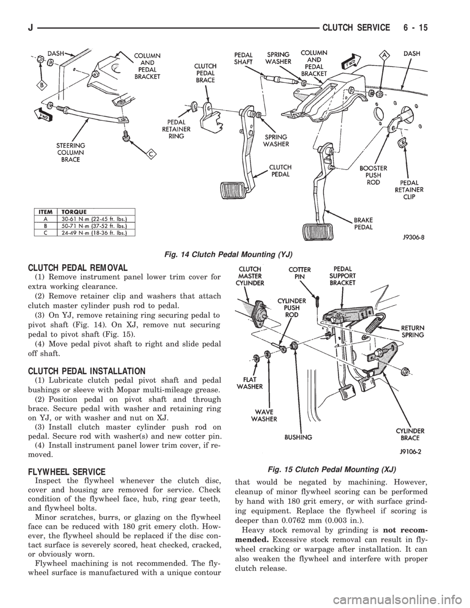
CLUTCH PEDAL REMOVAL
(1) Remove instrument panel lower trim cover for
extra working clearance.
(2) Remove retainer clip and washers that attach
clutch master cylinder push rod to pedal.
(3) On YJ, remove retaining ring securing pedal to
pivot shaft (Fig. 14). On XJ, remove nut securing
pedal to pivot shaft (Fig. 15).
(4) Move pedal pivot shaft to right and slide pedal
off shaft.
CLUTCH PEDAL INSTALLATION
(1) Lubricate clutch pedal pivot shaft and pedal
bushings or sleeve with Mopar multi-mileage grease.
(2) Position pedal on pivot shaft and through
brace. Secure pedal with washer and retaining ring
on YJ, or with washer and nut on XJ.
(3) Install clutch master cylinder push rod on
pedal. Secure rod with washer(s) and new cotter pin.
(4) Install instrument panel lower trim cover, if re-
moved.
FLYWHEEL SERVICE
Inspect the flywheel whenever the clutch disc,
cover and housing are removed for service. Check
condition of the flywheel face, hub, ring gear teeth,
and flywheel bolts.
Minor scratches, burrs, or glazing on the flywheel
face can be reduced with 180 grit emery cloth. How-
ever, the flywheel should be replaced if the disc con-
tact surface is severely scored, heat checked, cracked,
or obviously worn.
Flywheel machining is not recommended. The fly-
wheel surface is manufactured with a unique contourthat would be negated by machining. However,
cleanup of minor flywheel scoring can be performed
by hand with 180 grit emery, or with surface grind-
ing equipment. Replace the flywheel if scoring is
deeper than 0.0762 mm (0.003 in.).
Heavy stock removal by grinding isnot recom-
mended.Excessive stock removal can result in fly-
wheel cracking or warpage after installation. It can
also weaken the flywheel and interfere with proper
clutch release.
Fig. 14 Clutch Pedal Mounting (YJ)
Fig. 15 Clutch Pedal Mounting (XJ)
JCLUTCH SERVICE 6 - 15
Page 237 of 1784
DIAGNOSIS
INDEX
page page
DRB Scan Tool........................... 5
On-Board Diagnostics (OBD)................. 4Preliminary Checks........................ 5
ON-BOARD DIAGNOSTICS (OBD)
FOR COOLING SYSTEM COMPONENTS
The powertrain control module (PCM) has been
programmed to monitor the certain following cooling
system components:
²If the engine has remained cool for too long a pe-
riod, such as with a stuck open thermostat, a Diag-
nostic Trouble Code (DTC) number 17 can be
observed at the Check Engine Lamp.
²If an open or shorted condition has developed in
the relay circuit controlling the electric radiator fan,
a Diagnostic Trouble Code (DTC) number 35 can be
observed at the Check Engine Lamp.
If the problem is sensed in a monitored circuit of-
ten enough to indicate an actual problem, a DTC is
stored. The DTC will be stored in the PCM memory
for eventual display to the service technician. If the
problem is repaired or ceases to exist, the PCM can-
cels the DTC after 51 engine starts.
Certain criteria must be met for a DTC to be en-
tered into PCM memory. The criteria may be a spe-
cific range of engine rpm, engine temperature and/or
input voltage to the PCM.
A DTC indicates that the PCM has recognized an
abnormal signal in a circuit or the system. A DTC
may indicate the result of a failure, but never iden-
tify the failed component directly.
It is possible that a DTC for a monitored circuit
may not be entered into memory even though a mal-
function has occurred. Refer to On-Board Diagnostics
(OBD) in Group 14, Fuel Systems for additional in-
formation.
ACCESSING DIAGNOSTIC TROUBLE CODES
A stored Diagnostic Trouble Code (DTC) can be dis-
played by cycling the ignition key On-Off-On-Off-On
within three seconds and observing the Malfunction
Indicator Lamp. This lamp was formerly referred to
as the Check Engine Lamp. The lamp is located on
the instrument panel.
They can also be displayed through the use of the
Diagnostic Readout Box (DRB) scan tool. The DRB
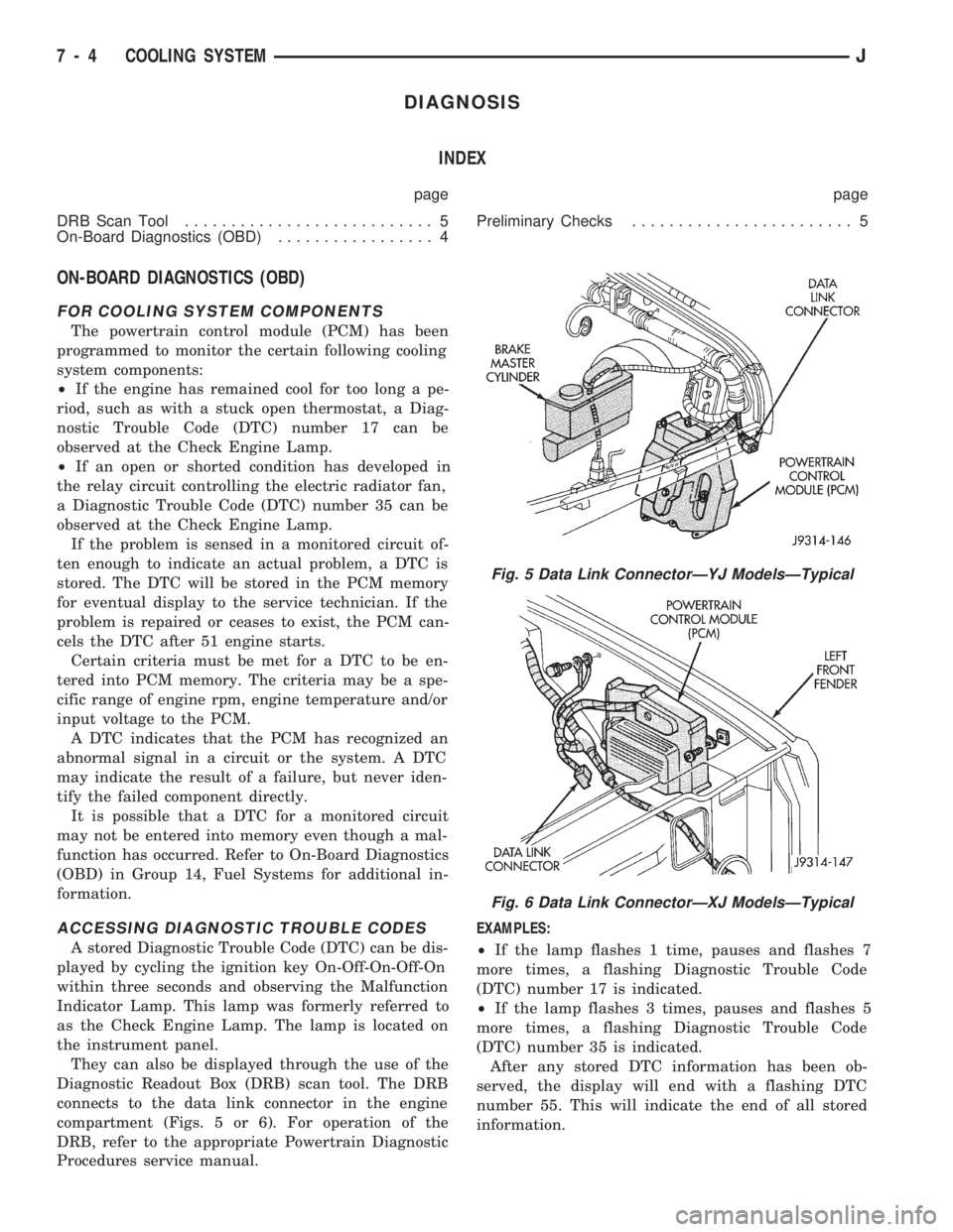
connects to the data link connector in the engine
compartment (Figs. 5 or 6). For operation of the
DRB, refer to the appropriate Powertrain Diagnostic
Procedures service manual.EXAMPLES:
²If the lamp flashes 1 time, pauses and flashes 7
more times, a flashing Diagnostic Trouble Code
(DTC) number 17 is indicated.
²If the lamp flashes 3 times, pauses and flashes 5
more times, a flashing Diagnostic Trouble Code
(DTC) number 35 is indicated.
After any stored DTC information has been ob-
served, the display will end with a flashing DTC
number 55. This will indicate the end of all stored
information.
Fig. 5 Data Link ConnectorÐYJ ModelsÐTypical
Fig. 6 Data Link ConnectorÐXJ ModelsÐTypical
7 - 4 COOLING SYSTEMJ
Page 262 of 1784
through the relay. When coolant temperature is be-
low 88ÉC (190ÉF), the PCM opens the ground path to
the relay. This will prevent the cooling fan from be-
ing energized.
Whenever the air conditioning is used, the PCM
engages the auxiliary cooling fan. It provides a
ground path to the cooling fan relay.
DIAGNOSIS
The powertrain control module (PCM) will enter a
diagnostic trouble code (DTC) number 35 in memory
if it detects a problem in the auxiliary cooling fan re-
lay or circuit. This will be read as a flashing signal
at the instrument panel mounted Malfunction Indica-
tor Lamp (formerly referred to as the Check Engine
Lamp). Refer to On-Board Diagnostics in Group 14,
Fuel Systems for information on accessing a DTC.
The DTC can also be accessed through the DRB
scan tool. Refer to the appropriate Powertrain Diag-
nostic Procedures manual for diagnostic information
and operation of the DRB scan tool.
REMOVAL
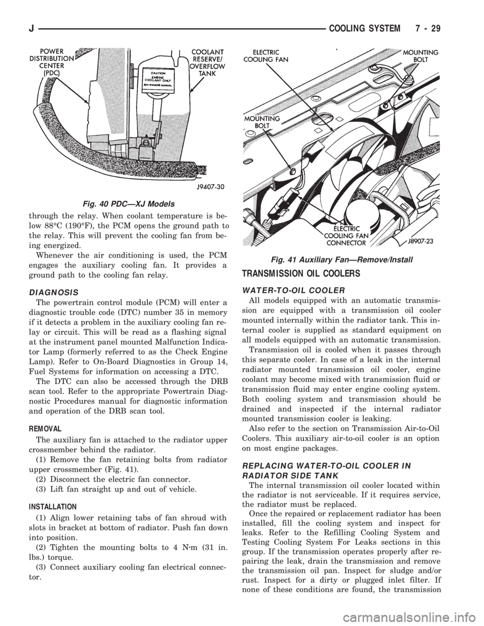
The auxiliary fan is attached to the radiator upper
crossmember behind the radiator.
(1) Remove the fan retaining bolts from radiator
upper crossmember (Fig. 41).
(2) Disconnect the electric fan connector.
(3) Lift fan straight up and out of vehicle.
INSTALLATION
(1) Align lower retaining tabs of fan shroud with
slots in bracket at bottom of radiator. Push fan down
into position.
(2) Tighten the mounting bolts to 4 Nzm (31 in.
lbs.) torque.
(3) Connect auxiliary cooling fan electrical connec-
tor.
TRANSMISSION OIL COOLERS
WATER-TO-OIL COOLER
All models equipped with an automatic transmis-
sion are equipped with a transmission oil cooler
mounted internally within the radiator tank. This in-
ternal cooler is supplied as standard equipment on
all models equipped with an automatic transmission.
Transmission oil is cooled when it passes through
this separate cooler. In case of a leak in the internal
radiator mounted transmission oil cooler, engine
coolant may become mixed with transmission fluid or
transmission fluid may enter engine cooling system.
Both cooling system and transmission should be
drained and inspected if the internal radiator
mounted transmission cooler is leaking.
Also refer to the section on Transmission Air-to-Oil
Coolers. This auxiliary air-to-oil cooler is an option
on most engine packages.
REPLACING WATER-TO-OIL COOLER IN
RADIATOR SIDE TANK
The internal transmission oil cooler located within
the radiator is not serviceable. If it requires service,
the radiator must be replaced.
Once the repaired or replacement radiator has been
installed, fill the cooling system and inspect for
leaks. Refer to the Refilling Cooling System and
Testing Cooling System For Leaks sections in this
group. If the transmission operates properly after re-
pairing the leak, drain the transmission and remove
the transmission oil pan. Inspect for sludge and/or
rust. Inspect for a dirty or plugged inlet filter. If
none of these conditions are found, the transmission
Fig. 40 PDCÐXJ Models
Fig. 41 Auxiliary FanÐRemove/Install
JCOOLING SYSTEM 7 - 29
Page 274 of 1784
ELECTRICAL
GROUP INDEX
Group Group
AUDIO SYSTEMS....................... 8F
BATTERY/STARTER/GENERATOR SERVICE . . 8B
BATTERY/STARTING/CHARGING SYSTEMS
DIAGNOSTICS........................ 8A
CHIME/WARNING BUZZER SYSTEM....... 8U
HORNS............................... 8G
IGNITION SYSTEMS.................... 8D
INSTRUMENT PANEL AND GAUGES........ 8E
LAMPS............................... 8L
OVERHEAD CONSOLE................... 8CPOWER LOCKS........................ 8P
POWER MIRRORS...................... 8T
POWER SEAT.......................... 8R
POWER WINDOWS..................... 8S
REAR WINDOW DEFOGGER.............. 8N
TURN SIGNALS AND HAZARD WARNING
FLASHERS........................... 8J
VEHICLE SPEED CONTROL SYSTEM....... 8H
WINDSHIELD WIPERS AND WASHERS..... 8K
WIRING DIAGRAMS.................... 8W
BATTERY/STARTING/CHARGING SYSTEMS DIAGNOSTICS
CONTENTS
page page
BATTERY TEST PROCEDURES............. 2
ENGINE STARTER MOTOR TEST
PROCEDURES ON VEHICLE.............. 9GENERATOR TEST PROCEDURES ON
VEHICLE............................. 14
IGNITION OFF DRAW (IOD) DIAGNOSIS...... 8
USING ON-BOARD DIAGNOSTIC SYSTEM.... 19
GENERAL INFORMATION
The battery, starting, and charging systems oper-
ate with one another, and therefore, must be thor-
oughly tested as a complete system. In order for the
vehicle to start and charge properly, it must have a
battery that will perform to specifications. The
starter motor, generator, wiring, and electronics also
must perform within specifications. Group 8A covers
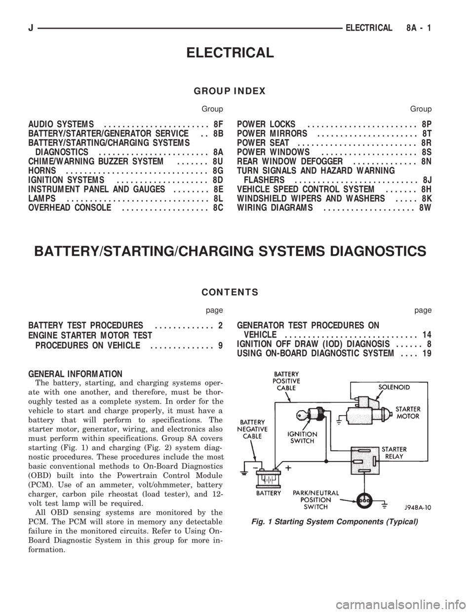
starting (Fig. 1) and charging (Fig. 2) system diag-
nostic procedures. These procedures include the most
basic conventional methods to On-Board Diagnostics
(OBD) built into the Powertrain Control Module
(PCM). Use of an ammeter, volt/ohmmeter, battery
charger, carbon pile rheostat (load tester), and 12-
volt test lamp will be required.
All OBD sensing systems are monitored by the
PCM. The PCM will store in memory any detectable
failure in the monitored circuits. Refer to Using On-
Board Diagnostic System in this group for more in-
formation.
Fig. 1 Starting System Components (Typical)
JELECTRICAL 8A - 1
Page 332 of 1784
With the ignition key in the ON position and en-
gine not running, check the sensor output voltage at
the center terminal wire of the connector. Check this
at idle (throttle plate closed) and at wide open throt-
tle (WOT). At idle, sensor output voltage should be
greater than 200 millivolts. At wide open throttle,
sensor output voltage must be less than 4.8 volts.
The output voltage should increase gradually as the
throttle plate is slowly opened from idle to WOT.
OXYGEN SENSOR TESTS
For diagnosis, removal or installation, refer to
Group 14, Fuel Systems in this manual.
ON-BOARD DIAGNOSTICS (OBD)
FOR IGNITION SYSTEM COMPONENTS
The powertrain control module (PCM) has been
programmed to monitor certain ignition system cir-
cuits:
EXAMPLE:
If a reference signal is not being detected during
engine cranking from the crankshaft position sensor,
a Diagnostic Trouble Code (DTC) number 11 can be
observed at the Check Engine Lamp.
If the problem is sensed in a monitored circuit of-
ten enough to indicate an actual problem, a DTC is
stored. The DTC will be stored in the PCM memory
for eventual display to the service technician. If the
problem is repaired or ceases to exist, the PCM can-
cels the DTC after 51 engine starts.
Certain criteria must be met for a DTC to be en-
tered into PCM memory. The criteria may be a spe-
cific range of engine rpm, engine temperature and/or
input voltage to the PCM.
A DTC indicates that the PCM has recognized an
abnormal signal in a circuit or the system. A DTC
may indicate the result of a failure, but never iden-
tify the failed component directly.
It is possible that a DTC for a monitored circuit
may not be entered into memory even though a mal-
function has occurred. Refer to On-Board Diagnostics
(OBD) in Group 14, Fuel Systems for additional in-
formation.
ACCESSING DIAGNOSTIC TROUBLE CODES
A stored Diagnostic Trouble Code (DTC) can be dis-
played by cycling the ignition key On-Off-On-Off-On
within three seconds and observing the Malfunction
Indicator Lamp. This lamp was formerly referred to
as the Check Engine Lamp. The lamp is located on
the instrument panel.
They can also be displayed through the use of the
Diagnostic Readout Box (DRB) scan tool. The DRB
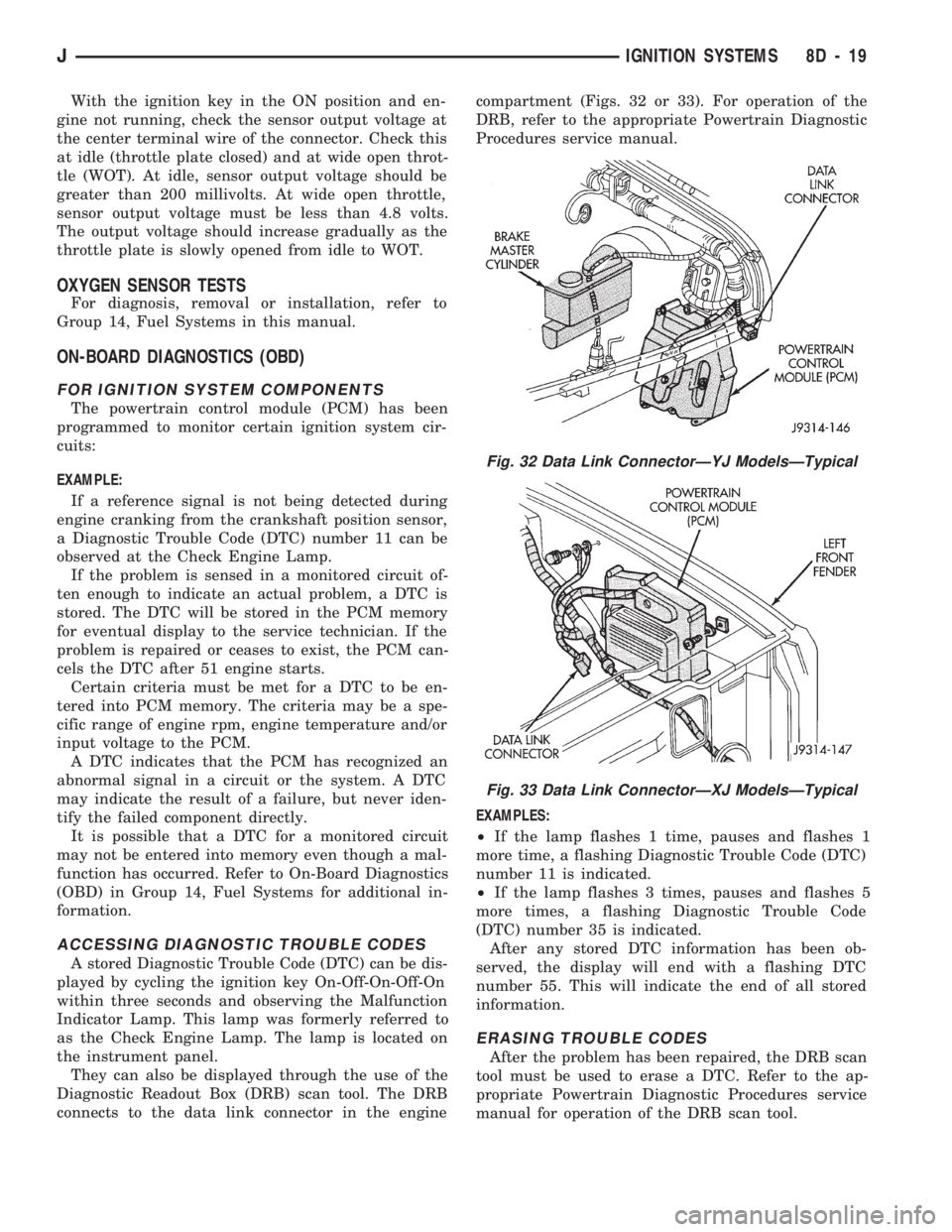
connects to the data link connector in the enginecompartment (Figs. 32 or 33). For operation of the
DRB, refer to the appropriate Powertrain Diagnostic
Procedures service manual.
EXAMPLES:
²If the lamp flashes 1 time, pauses and flashes 1
more time, a flashing Diagnostic Trouble Code (DTC)
number 11 is indicated.
²If the lamp flashes 3 times, pauses and flashes 5
more times, a flashing Diagnostic Trouble Code
(DTC) number 35 is indicated.
After any stored DTC information has been ob-
served, the display will end with a flashing DTC
number 55. This will indicate the end of all stored
information.
ERASING TROUBLE CODES
After the problem has been repaired, the DRB scan
tool must be used to erase a DTC. Refer to the ap-
propriate Powertrain Diagnostic Procedures service
manual for operation of the DRB scan tool.
Fig. 32 Data Link ConnectorÐYJ ModelsÐTypical
Fig. 33 Data Link ConnectorÐXJ ModelsÐTypical
JIGNITION SYSTEMS 8D - 19
Page 343 of 1784

IGNITION SWITCH
INDEX
page page
General Information....................... 30
Ignition Switch Installation/Adjustment......... 31Ignition Switch Removal................... 30
Ignition Switch Testing..................... 30
GENERAL INFORMATION
The ignition switch is mounted (under the instru-
ment panel) on the lower section of the steering col-
umn. The headlamp dimmer switch is mounted
beside the ignition switch (Fig. 1). Both of these
switches (ignition and dimmer) share the same
mounting screws.
The switch is connected to the ignition key lock as-
sembly by a remote actuator rod. This remote actua-
tor rod fits into an access hole on the bottom of the
ignition switch (Fig. 2).
IGNITION SWITCH REMOVAL
(1) Disconnect the negative battery cable at the
battery.
(2) XJ models: Remove the lower instrument panel
trim assembly. YJ models: Remove the windshield
wiper intermittent control module and its bracket (if
equipped).
(3) Place the ignition key lock in ACCESSORY po-
sition.
(4) Remove the two headlamp dimmer switch at-
taching nuts. Lift the switch from steering column
while disengaging actuator rod.Before removing dimmer switch, tape the two
remote control actuator rods (ignition switch
and dimmer) to the steering column. This will
prevent accidental disengagement from the up-
per part of the steering column.
(5) Remove the ignition switch-to-steering column
attaching screws.
(6) Disengage the ignition switch from the remote
actuator rod by lifting straight up. Remove switch
from steering column.
(7) Remove wiring from switch as follows:
Two electrical connectors are used to connect all
wiring to the ignition switch. One of the connectors
is installed (interlocked) over the top of the other
connector. Remove wiring from switch by disconnect-
ing the (black) harness connector first and then the
other connector. Remove the switch from the vehicle.
IGNITION SWITCH TESTING
To test the ignition switch circuity and continuity,
proceed as follows. Place the slide bar (on the igni-
tion switch) (Fig. 2) into the detent position to be
tested. An ohmmeter or continuity light may be used
to check switch continuity. Refer to the Ignition
Fig. 1 Ignition Switch/Headlamp Dimmer
SwitchÐTypical
Fig. 2 Ignition Switch/Remote Actuator
RodÐTypical
8D - 30 IGNITION SYSTEMSJ
Page 345 of 1784

taching screws. Do not allow the ignition switch to
move from the ACCESSORY detent position.
Because the ignition switch and the headlamp dim-
mer switch share the same two mounting screws, one
of the screws must be removed from the ignition
switch. This must be doneafterthe ignition switch
has been adjusted andbeforethe dimmer switch has
been installed. Remove one screw.Do notremove
the stud/nut.
(7) Install the headlamp dimmer switch as follows:
Slip switch into actuator rod and position over the ig-
nition switch. Install screws finger tight. Remove the
dimmer switch actuator rod securing-tape from steer-
ing column.
(8) Adjust dimmer switch as follows: Depress the
switch slightly and insert a 3/32-inch drill bit into
the adjustment hole (Fig. 1). This is done to prevent
horizontal switch movement.
(9) Move switch toward steering wheel to remove
any lash from switch actuator rod. Tighten dimmer
and ignition switch fasteners to 4 Nzm (35 in. lbs.)
torque.
(10) XJ models: Install the lower instrument panel
trim assembly. YJ models: Install the windshield
wiper intermittent control module and its bracket (if
equipped).
(11) Install the negative battery cable.
Test dimmer switch. Test ignition switch operation
in all switch positions. If equipped with a tilt steer-
ing column, test operation of dimmer switch and ig-
nition switch in all tilt positions.
Fig. 4 Detent PositionsÐNon-Tilt Steering Column
Fig. 5 Detent PositionsÐTilt Steering Column
8D - 32 IGNITION SYSTEMSJ
Page 348 of 1784

INSTRUMENT PANEL AND GAUGES
GROUP INDEX
page page
INSTRUMENT PANEL AND GAUGESÐXJ..... 1INSTRUMENT PANEL AND GAUGESÐYJ.... 14
INSTRUMENT PANEL AND GAUGESÐXJE
CONTENTS
page page
INSTRUMENT CLUSTER DIAGNOSIS........ 3
INSTRUMENT CLUSTER GENERAL INFORMATION.. 1
INSTRUMENT CLUSTER SERVICE PROCEDURES... 5
SPECIFICATIONS....................... 13
INSTRUMENT CLUSTER GENERAL INFORMATION
INDEX
page page
4WD Indicator Lamp........................ 2
Anti-Lock Brake Indicator Lamp............... 2
Brake Indicator Lamp....................... 2
Coolant Temperature Gauge................. 1
Coolant Temperature Indicator Lamp........... 1
Fuel Gauge.............................. 2
Low Fuel Warning Lamp..................... 2Malfunction Indicator Lamp (Check Engine)...... 2
Oil Pressure Gauge....................... 1
Oil Pressure Indicator Lamp.................. 1
Speedometer/Odometer System.............. 2
Tachometer.............................. 2
Upshift Indicator Lamp...................... 2
Voltmeter............................... 1
With the ignition switch in the ON or START posi-
tion, voltage supplied to the instrument cluster is lim-
ited by fuse #17. The voltage is supplied to all the
gauges and indicator lamps through the instrument
cluster printed circuit.
With the ignition switch in the OFF position, volt-
age is not supplied to the instrument cluster and the
gauges do not indicate any vehicle condition.
VOLTMETER
The voltmeter measures battery or generator out-
put voltage, whichever is greater.
OIL PRESSURE GAUGE
The oil pressure gauge pointer position is controlled
by a magnetic field created by electrical current flow
through the coils within the gauge. A change in current
flow will change the magnetic field which changes the
pointer position. The oil pressure sender is a variable
resistor that changes electrical resistance with a change
in oil pressure (values shown in Specifications chart).
OIL PRESSURE INDICATOR LAMP
Voltage is supplied to one side of the indicator bulb
and the oil pressure switch is connected to the other
side. When oil pressure is too low the switch closes
providing a path to ground, and the indicator bulb
lights.
COOLANT TEMPERATURE GAUGE
The coolant temperature gauge pointer position is
controlled by a magnetic field created by electrical
current flow through the coils within the gauge. A
change in current flow will change the magnetic field
which changes the pointer position. The coolant tem-
perature sensor is a thermistor that changes electri-
cal resistance with a change in coolant temperature
(values shown in Specifications chart).
COOLANT TEMPERATURE INDICATOR LAMP
Voltage is supplied to one side of the indicator bulb
and the coolant temperature switch is connected to the
JINSTRUMENT PANEL AND GAUGES 8E - 1