Page 373 of 1784
Fig. 20 Gauge Package Lens Removal
8E - 26 YJ INSTRUMENT PANEL AND GAUGESJ
Page 374 of 1784
SPECIFICATIONS
INSTRUMENT PANEL GAUGES
INSTRUMENT CLUSTER GAUGES
JYJ INSTRUMENT PANEL AND GAUGES 8E - 27
Page 378 of 1784
²Inspect secondary ignition system components:
wire routing and condition, distributor cap and rotor,
ignition coil, spark plugs. Reroute or replace as re-
quired.RADIO ILLUMINATION RELAY
XJ
The radio illumination relay is in the relay center.
The relay center is located on the lower instrument
panel trim cover, right of the steering column
(Fig. 2).
YJ
The radio illumination relay is taped to the har-
ness above the radio.
RADIO CONNECTOR PINS
Fig. 2 Radio Illumination Relay
JAUDIO SYSTEMS 8F - 3
Page 379 of 1784
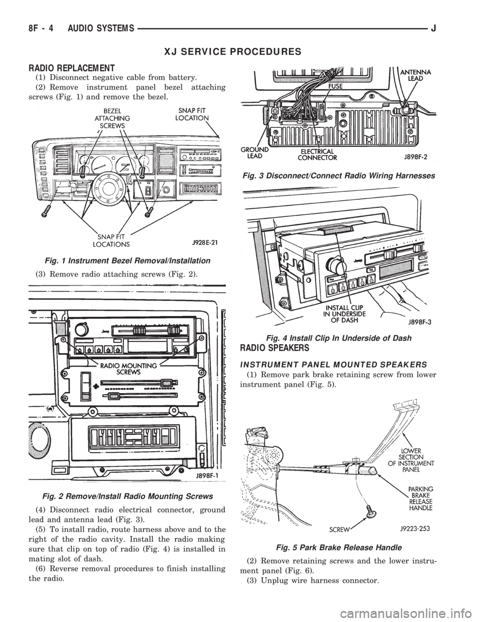
XJ SERVICE PROCEDURES
RADIO REPLACEMENT
(1) Disconnect negative cable from battery.
(2) Remove instrument panel bezel attaching
screws (Fig. 1) and remove the bezel.
(3) Remove radio attaching screws (Fig. 2).
(4) Disconnect radio electrical connector, ground
lead and antenna lead (Fig. 3).
(5) To install radio, route harness above and to the
right of the radio cavity. Install the radio making
sure that clip on top of radio (Fig. 4) is installed in
mating slot of dash.
(6) Reverse removal procedures to finish installing
the radio.
RADIO SPEAKERS
INSTRUMENT PANEL MOUNTED SPEAKERS
(1) Remove park brake retaining screw from lower
instrument panel (Fig. 5).
(2) Remove retaining screws and the lower instru-
ment panel (Fig. 6).
(3) Unplug wire harness connector.
Fig. 3 Disconnect/Connect Radio Wiring Harnesses
Fig. 4 Install Clip In Underside of Dash
Fig. 5 Park Brake Release Handle
Fig. 1 Instrument Bezel Removal/Installation
Fig. 2 Remove/Install Radio Mounting Screws
8F - 4 AUDIO SYSTEMSJ
Page 380 of 1784
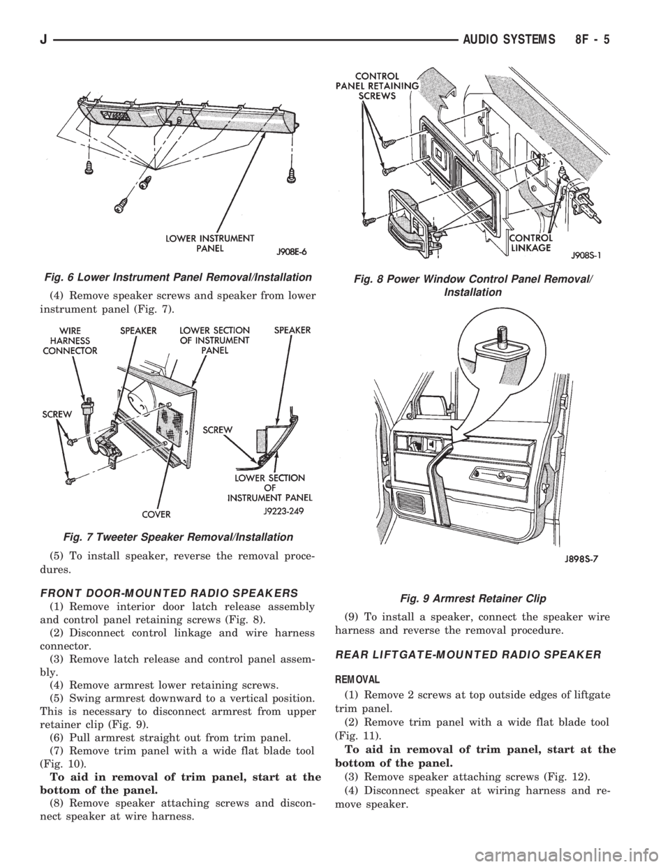
(4) Remove speaker screws and speaker from lower
instrument panel (Fig. 7).
(5) To install speaker, reverse the removal proce-
dures.
FRONT DOOR-MOUNTED RADIO SPEAKERS
(1) Remove interior door latch release assembly
and control panel retaining screws (Fig. 8).
(2) Disconnect control linkage and wire harness
connector.
(3) Remove latch release and control panel assem-
bly.
(4) Remove armrest lower retaining screws.
(5) Swing armrest downward to a vertical position.
This is necessary to disconnect armrest from upper
retainer clip (Fig. 9).
(6) Pull armrest straight out from trim panel.
(7) Remove trim panel with a wide flat blade tool
(Fig. 10).
To aid in removal of trim panel, start at the
bottom of the panel.
(8) Remove speaker attaching screws and discon-
nect speaker at wire harness.(9) To install a speaker, connect the speaker wire
harness and reverse the removal procedure.
REAR LIFTGATE-MOUNTED RADIO SPEAKER
REMOVAL
(1) Remove 2 screws at top outside edges of liftgate
trim panel.
(2) Remove trim panel with a wide flat blade tool
(Fig. 11).
To aid in removal of trim panel, start at the
bottom of the panel.
(3) Remove speaker attaching screws (Fig. 12).
(4) Disconnect speaker at wiring harness and re-
move speaker.
Fig. 6 Lower Instrument Panel Removal/Installation
Fig. 7 Tweeter Speaker Removal/Installation
Fig. 8 Power Window Control Panel Removal/
Installation
Fig. 9 Armrest Retainer Clip
JAUDIO SYSTEMS 8F - 5
Page 381 of 1784
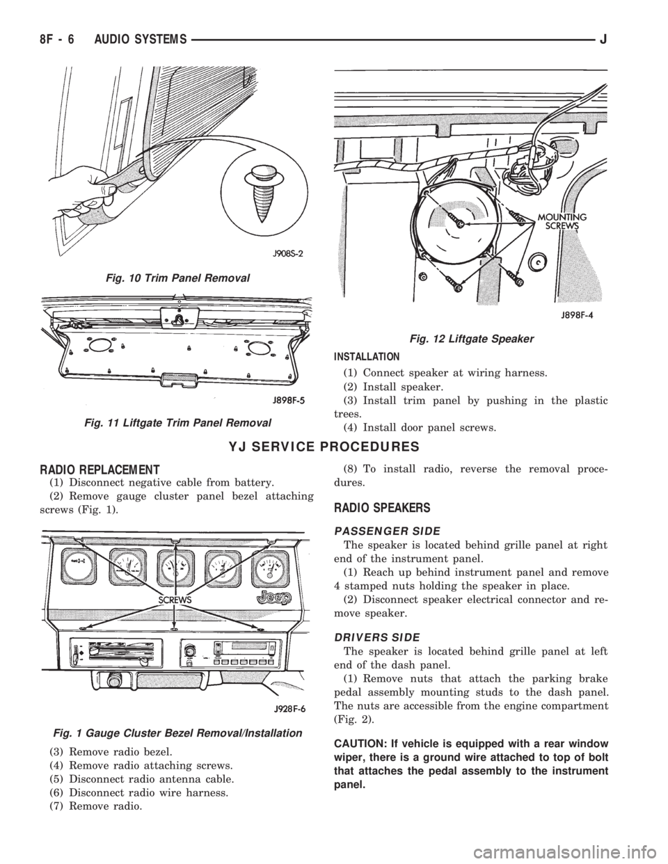
INSTALLATION
(1) Connect speaker at wiring harness.
(2) Install speaker.
(3) Install trim panel by pushing in the plastic
trees.
(4) Install door panel screws.
YJ SERVICE PROCEDURES
RADIO REPLACEMENT
(1) Disconnect negative cable from battery.
(2) Remove gauge cluster panel bezel attaching
screws (Fig. 1).
(3) Remove radio bezel.
(4) Remove radio attaching screws.
(5) Disconnect radio antenna cable.
(6) Disconnect radio wire harness.
(7) Remove radio.(8) To install radio, reverse the removal proce-
dures.
RADIO SPEAKERS
PASSENGER SIDE
The speaker is located behind grille panel at right
end of the instrument panel.
(1) Reach up behind instrument panel and remove
4 stamped nuts holding the speaker in place.
(2) Disconnect speaker electrical connector and re-
move speaker.
DRIVERS SIDE
The speaker is located behind grille panel at left
end of the dash panel.
(1) Remove nuts that attach the parking brake
pedal assembly mounting studs to the dash panel.
The nuts are accessible from the engine compartment
(Fig. 2).
CAUTION: If vehicle is equipped with a rear window
wiper, there is a ground wire attached to top of bolt
that attaches the pedal assembly to the instrument
panel.
Fig. 10 Trim Panel Removal
Fig. 11 Liftgate Trim Panel Removal
Fig. 12 Liftgate Speaker
Fig. 1 Gauge Cluster Bezel Removal/Installation
8F - 6 AUDIO SYSTEMSJ
Page 382 of 1784
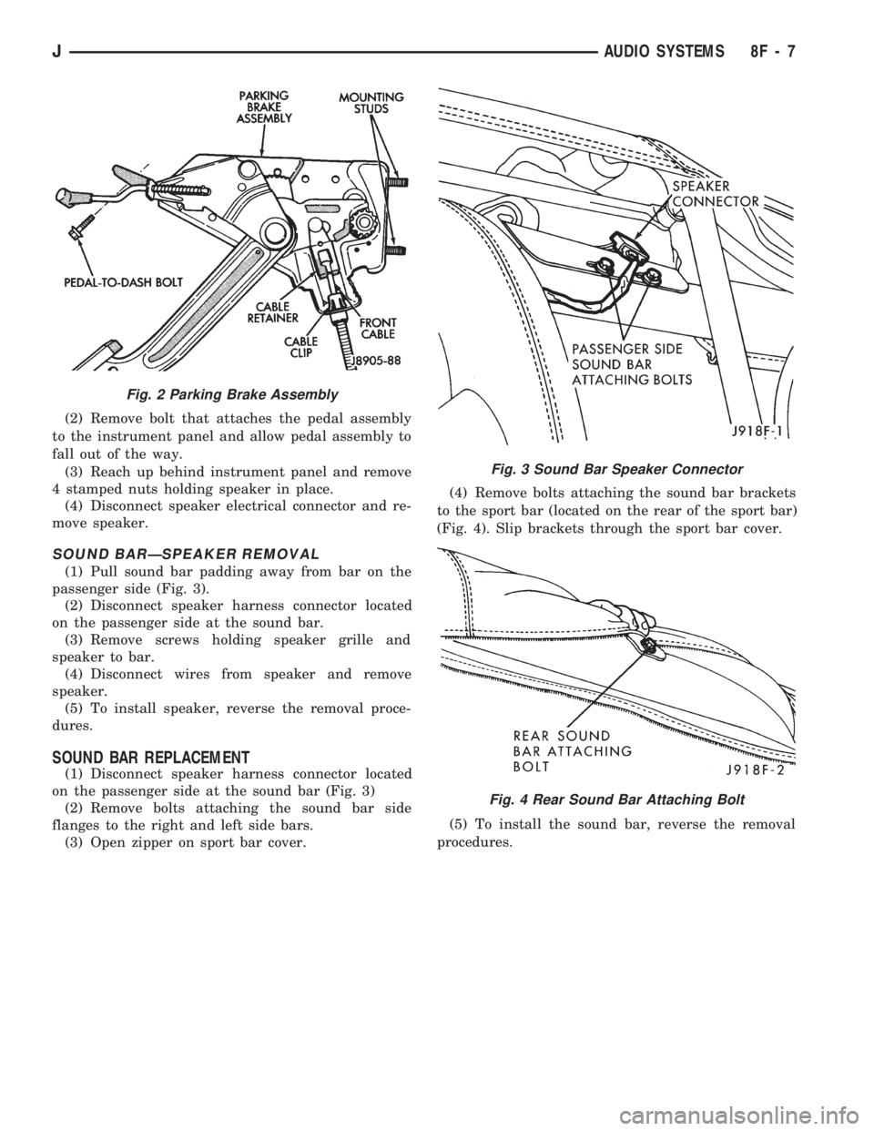
(2) Remove bolt that attaches the pedal assembly
to the instrument panel and allow pedal assembly to
fall out of the way.
(3) Reach up behind instrument panel and remove
4 stamped nuts holding speaker in place.
(4) Disconnect speaker electrical connector and re-
move speaker.
SOUND BARÐSPEAKER REMOVAL
(1) Pull sound bar padding away from bar on the
passenger side (Fig. 3).
(2) Disconnect speaker harness connector located
on the passenger side at the sound bar.
(3) Remove screws holding speaker grille and
speaker to bar.
(4) Disconnect wires from speaker and remove
speaker.
(5) To install speaker, reverse the removal proce-
dures.
SOUND BAR REPLACEMENT
(1) Disconnect speaker harness connector located
on the passenger side at the sound bar (Fig. 3)
(2) Remove bolts attaching the sound bar side
flanges to the right and left side bars.
(3) Open zipper on sport bar cover.(4) Remove bolts attaching the sound bar brackets
to the sport bar (located on the rear of the sport bar)
(Fig. 4). Slip brackets through the sport bar cover.
(5) To install the sound bar, reverse the removal
procedures.
Fig. 2 Parking Brake Assembly
Fig. 3 Sound Bar Speaker Connector
Fig. 4 Rear Sound Bar Attaching Bolt
JAUDIO SYSTEMS 8F - 7
Page 383 of 1784
RADIO ANTENNA
INDEX
page page
Antenna Tests............................ 9
General Information........................ 8Replacement............................. 8
GENERAL INFORMATION
AM/FM radio model antennas must have a good
ground to eliminate static. The antenna mast is con-
nected to the inner wire of the coaxial cable and is
not grounded to any part of the vehicle. The coaxial
shield (the wire mesh) surrounding the center con-
ductor wire of the antenna lead-in cable is grounded
to the radio and the antenna base.
REPLACEMENT
XJ
(1) Remove the fender inner splash panel mount-
ing nuts (Fig. 1) and move the panel aside to gain ac-
cess to the antenna base and cable.
The splash panel screws may be covered with
undercoating.
(2) Remove the antenna mast, nut and antenna
pad from the top of the fender (Fig. 2).
(3) Remove the passenger side kick panel.
(4) Disconnect the antenna lead (Fig. 3) by pulling
apart while twisting the metal connectors. DO NOT
PULL ON THE COAXIAL CABLE.
(5) Pull the rubber grommet out of the kick panel.(6) Remove the antenna assembly from inside the
wheel well.
(7) To install the antenna, reverse the removal
procedure.
(8) Verify antenna and radio operation.
(9) Apply 3M Rubberized Undercoating, or equiva-
lent to the splash panel screws.
YJ
(1) Remove the radio as described in Radio Re-
placement.
(2) Remove three screws holding the antenna base
and pad to the body (Fig. 4).
(3) Pull the antenna and cable out of the vehicle.
(4) To install the antenna, make sure the antenna
pad is placed over the cable and guide the cable un-
der the instrument panel.
(5) Secure the antenna base and pad with three screws.
(6) Install the antenna into the radio and install
the radio.
Fig. 1 Remove/Install Fender Inner Splash Panel
Fig. 2 Remove/Install Nut and Antenna Pad
8F - 8 AUDIO SYSTEMSJ