1994 JEEP CHEROKEE instrument panel
[x] Cancel search: instrument panelPage 130 of 1784
EXTENDED IDLE SWITCH TEST
OPTIONAL POLICE PACKAGE ONLY
OPERATION
The extended idle switch is used to raise the en-
gine idle speed to approximately 1000 rpm when the
shifter is in either the Park or Neutral position. A
rocker-type 2-wire switch (extended idle switch) is
mounted to the instrument panel.This switch is
available only with 4.0L engine when supplied
with the optional police package.
TESTING
The extended idle switch will control a ground cir-
cuit going to the powertrain control module (PCM).
When a ground signal (through this switch) has been
received at pin number 10 in the PCM, engine idle
speed will increase.
Bring the engine to normal operating temperature
and turn the extended idle switch to the ON position.
Engine speed should now increase to approximately
1000 rpm when the shifter is in either the Park or
Neutral position. If engine speed does not increase,
apply a good ground to pin number 10 at the PCM
using a small paper clip. Be careful not to damage
the wiring with the paper clip. If the engine speed
now increases, it can be assumed that the PCM is
functioning correctly. Check the instrument panel
mounted switch for a closed ground circuit when in
the ON position. If the engine speed will not increase
after applying a ground to pin number 10, replace
the PCM. Refer to Group 8W, Wiring Diagrams for
circuit and wiring information.
THROTTLE POSITION SENSOR (TPS) TEST
To perform a complete test of the sensor and its cir-
cuitry, refer to DRB scan tool and appropriate Pow-
ertrain Diagnostics Procedures manual. To test the
sensor only, refer to the following:
The throttle position sensor (TPS) can be tested
with a digital voltmeter. The center terminal of the
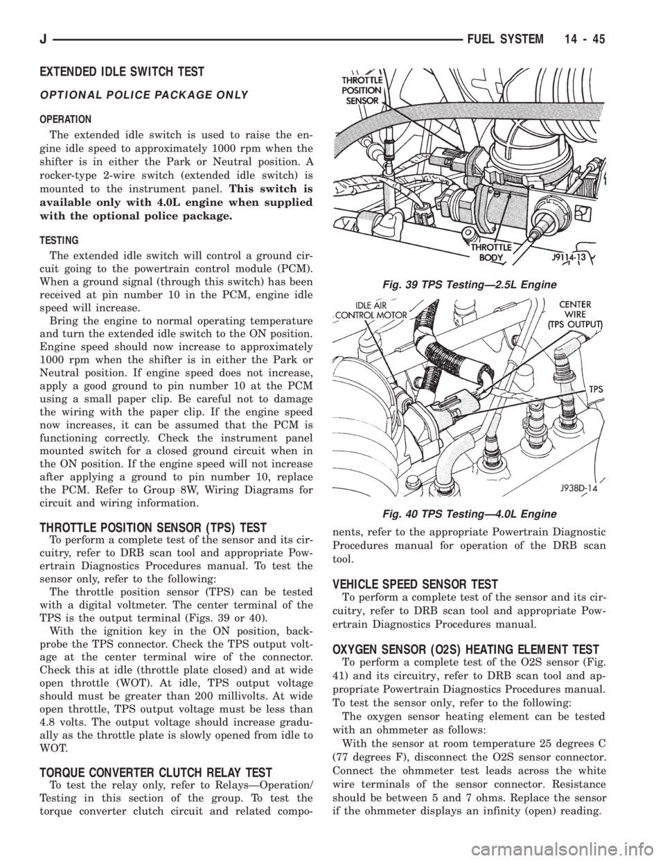
TPS is the output terminal (Figs. 39 or 40).
With the ignition key in the ON position, back-
probe the TPS connector. Check the TPS output volt-
age at the center terminal wire of the connector.
Check this at idle (throttle plate closed) and at wide
open throttle (WOT). At idle, TPS output voltage
should must be greater than 200 millivolts. At wide
open throttle, TPS output voltage must be less than
4.8 volts. The output voltage should increase gradu-
ally as the throttle plate is slowly opened from idle to
WOT.
TORQUE CONVERTER CLUTCH RELAY TEST
To test the relay only, refer to RelaysÐOperation/
Testing in this section of the group. To test the
torque converter clutch circuit and related compo-nents, refer to the appropriate Powertrain Diagnostic
Procedures manual for operation of the DRB scan
tool.
VEHICLE SPEED SENSOR TEST
To perform a complete test of the sensor and its cir-
cuitry, refer to DRB scan tool and appropriate Pow-
ertrain Diagnostics Procedures manual.
OXYGEN SENSOR (O2S) HEATING ELEMENT TEST
To perform a complete test of the O2S sensor (Fig.
41) and its circuitry, refer to DRB scan tool and ap-
propriate Powertrain Diagnostics Procedures manual.
To test the sensor only, refer to the following:
The oxygen sensor heating element can be tested
with an ohmmeter as follows:
With the sensor at room temperature 25 degrees C
(77 degrees F), disconnect the O2S sensor connector.
Connect the ohmmeter test leads across the white
wire terminals of the sensor connector. Resistance
should be between 5 and 7 ohms. Replace the sensor
if the ohmmeter displays an infinity (open) reading.
Fig. 39 TPS TestingÐ2.5L Engine
Fig. 40 TPS TestingÐ4.0L Engine
JFUEL SYSTEM 14 - 45
Page 135 of 1784
Excessive Oil Consumption: Although the PCM
monitors exhaust stream oxygen content through ox-
ygen sensor (closed loop), it cannot determine exces-
sive oil consumption.
Throttle Body Air Flow: The PCM cannot detect
a clogged or restricted air cleaner inlet or air filter
element.
Evaporative System: The PCM will not detect a
restricted, plugged or loaded EVAP canister.
Vacuum Assist: Leaks or restrictions in the vac-
uum circuits of vacuum assisted engine control sys-
tem devices are not monitored by the PCM. However,
a vacuum leak at the MAP sensor will be monitored
and a diagnostic trouble code (DTC) will be gener-
ated by the PCM.
Powertrain Control Module (PCM) System
Ground: The PCM cannot determine a poor system
ground. However, a DTC may be generated as a re-
sult of this condition.
Powertrain Control Module (PCM) Connector
Engagement: The PCM cannot determine spread or
damaged connector pins. However, a DTC may be
generated as a result of this condition.
HIGH AND LOW LIMITS
The powertrain control module (PCM) compares in-
put signal voltages from each input device. It will es-
tablish high and low limits that are programmed into
it for that device. If the input voltage is not within
specifications and other Diagnostic Trouble Code
(DTC) criteria are met, a DTC will be stored in mem-
ory. Other DTC criteria might include engine rpm
limits or input voltages from other sensors or
switches. The other inputs might have to be sensed
by the PCM when it senses a high or low input volt-
age from the control system device in question.
ACCESSING DIAGNOSTIC TROUBLE CODES
A stored Diagnostic Trouble Code (DTC) can be dis-
played by cycling the ignition key On-Off-On-Off-On
within three seconds and observing the Malfunction
Indicator Lamp. This lamp was formerly referred to
as the Check Engine Lamp. The lamp is located on
the instrument panel.
They can also be displayed through the use of the
Diagnostic Readout Box (DRB) scan tool. The DRB
scan tool connects to the data link connector in the
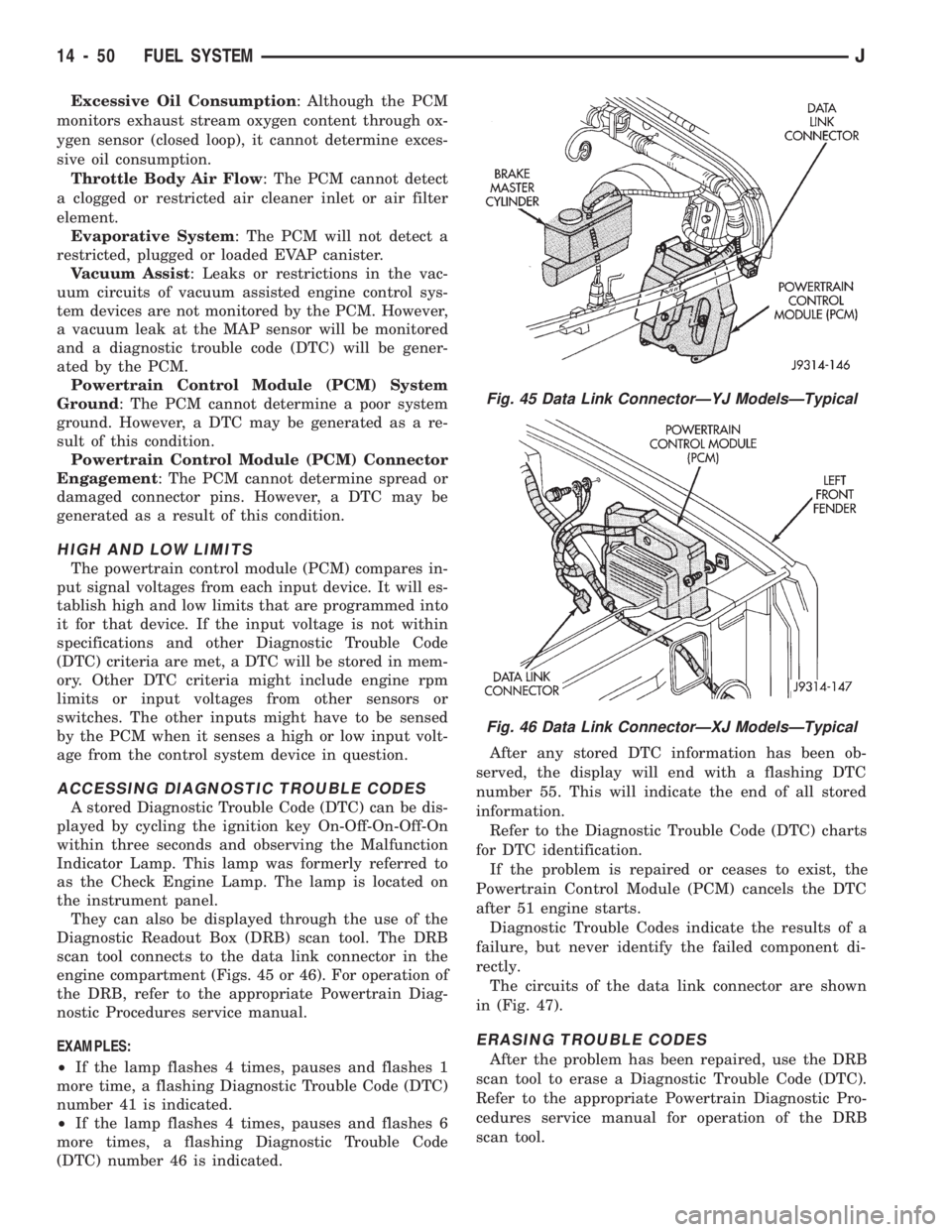
engine compartment (Figs. 45 or 46). For operation of
the DRB, refer to the appropriate Powertrain Diag-
nostic Procedures service manual.
EXAMPLES:
²If the lamp flashes 4 times, pauses and flashes 1
more time, a flashing Diagnostic Trouble Code (DTC)
number 41 is indicated.
²If the lamp flashes 4 times, pauses and flashes 6
more times, a flashing Diagnostic Trouble Code
(DTC) number 46 is indicated.After any stored DTC information has been ob-
served, the display will end with a flashing DTC
number 55. This will indicate the end of all stored
information.
Refer to the Diagnostic Trouble Code (DTC) charts
for DTC identification.
If the problem is repaired or ceases to exist, the
Powertrain Control Module (PCM) cancels the DTC
after 51 engine starts.
Diagnostic Trouble Codes indicate the results of a
failure, but never identify the failed component di-
rectly.
The circuits of the data link connector are shown
in (Fig. 47).
ERASING TROUBLE CODES
After the problem has been repaired, use the DRB
scan tool to erase a Diagnostic Trouble Code (DTC).
Refer to the appropriate Powertrain Diagnostic Pro-
cedures service manual for operation of the DRB
scan tool.
Fig. 45 Data Link ConnectorÐYJ ModelsÐTypical
Fig. 46 Data Link ConnectorÐXJ ModelsÐTypical
14 - 50 FUEL SYSTEMJ
Page 150 of 1784
ABS BRAKE DIAGNOSIS
INDEX
page page
ABS Fault Diagnosis....................... 4
ABS System Wiring and Electrical Circuits...... 4
ABS Warning Light Display.................. 3
Brake Warning Light Display................. 4
Diagnosis Procedures...................... 3
ECU Diagnosis........................... 4
HCU Diagnosis........................... 4Loss of Sensor Input....................... 3
Operating Sound Levels.................... 3
Rear Speed Sensor Air Gap................. 3
Steering Response........................ 3
Vehicle Response in Antilock Mode............ 3
Wheel/Tire Size and Input Signals............. 3
DIAGNOSIS PROCEDURES
ABS diagnosis involves three basic steps. First is
observation of the warning light display. Second is a
visual examination for low fluid level, leaks, parking
brakes applied, or obvious damage to system compo-
nents or wires. The third step involves using the
DRB II scan tool to identify a faulty component.
The visual examination requires a check of reser-
voir fluid level and all system components. Things to
look for are leaks, loose connections, or obvious com-
ponent damage.
The final diagnosis step involves using the DRB II
scan tool to determine the specific circuit or compo-
nent at fault. The tester is connected to the ABS di-
agnostic connector in the passenger compartment.
The connector is at the driver side of the center con-
sole under the instrument panel. Refer to the DRB II
scan tool Manual for tester procedures. Also refer to
the ABS Fault Diagnosis charts at the end of this
section for additional diagnosis information.
Initial faults should be cleared and the vehicle road
tested to reset any faults that remain in the system.
Faults can be cleared with the DRB II scan tool.
REAR SPEED SENSOR AIR GAP
The front wheel sensors are fixed and cannot be ad-
justed. Only the rear sensor air gap is adjustable. Air
gap must be set with a brass feeler gauge.
Correct air gap is important to proper signal gen-
eration. An air gap that is too large may cause com-
plete loss of sensor input. Or, a gap that is too small
could produce a false input signal, or damaging con-
tact between the sensor and tone ring.
WHEEL/TIRE SIZE AND INPUT SIGNALS
Antilock system operation is dependant on accurate
signals from the wheel speed sensors. Ideally, the ve-
hicle wheels and tires should all be the same size
and type. However, the Jeep ABS system is designed
to function with a compact spare tire installed.
OPERATING SOUND LEVELS
The ABS pump and solenoid valves may produce
some sound as they cycle on and off. This is a normal
condition and should not be mistaken for faulty oper-
ation.
VEHICLE RESPONSE IN ANTILOCK MODE
During antilock braking, the HCU solenoid valves
cycle rapidly in response to ECU inputs.
The driver will experience a pulsing sensation
within the vehicle as the solenoids decrease, hold, or
increase pressure as needed. A pulsing brake pedal
will also be noted.
The pulsing sensation occurs as the solenoids cycle
during antilock mode braking. A slight pulse in the
brake pedal may also be noted during the dynamic
self check part of system initialization.
STEERING RESPONSE
A modest amount of steering input is required dur-
ing extremely high deceleration braking, or when
braking on differing traction surfaces. An example of
differing traction surfaces would be when the left
side wheels are on ice and the right side wheels are
on dry pavement.
LOSS OF SENSOR INPUT
Sensor malfunctions will most likely be due to
loose connections, damaged sensor wires, incorrect
rear sensor air gap, or a malfunctioning sensor. Ad-
ditional causes of sensor faults would be sensor and
tone ring misalignment or damage.
ABS WARNING LIGHT DISPLAY
ABS Light Illuminates At Startup
The amber ABS light illuminates at startup as
part of the system self check feature. The light illu-
minates for 2-3 seconds then goes off as part of the
normal self check routine.
ABS Light Remains On After Startup
An ABS system fault is indicated when the light
remains on after startup. Diagnosis with the DRB II
JBRAKES 5 - 3
Page 169 of 1784
POWER BRAKE BOOSTER
INDEX
page page
Power Brake Booster Installation............. 23
Power Brake Booster Operation............. 22Power Brake Booster Removal.............. 22
Service Information....................... 22
SERVICE INFORMATION
The power brake booster is not a serviceable com-
ponent. If a booster malfunction occurs, the booster
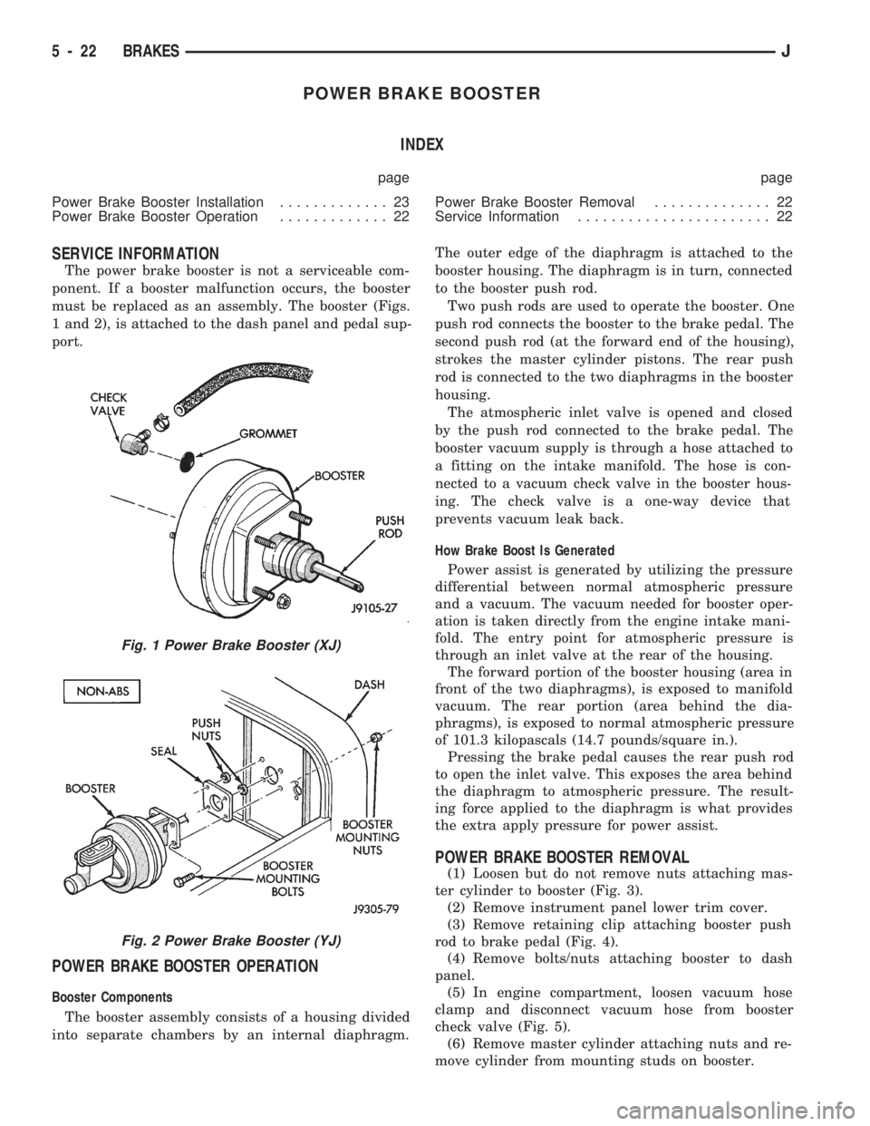
must be replaced as an assembly. The booster (Figs.
1 and 2), is attached to the dash panel and pedal sup-
port.
POWER BRAKE BOOSTER OPERATION
Booster Components
The booster assembly consists of a housing divided
into separate chambers by an internal diaphragm.The outer edge of the diaphragm is attached to the
booster housing. The diaphragm is in turn, connected
to the booster push rod.
Two push rods are used to operate the booster. One
push rod connects the booster to the brake pedal. The
second push rod (at the forward end of the housing),
strokes the master cylinder pistons. The rear push
rod is connected to the two diaphragms in the booster
housing.
The atmospheric inlet valve is opened and closed
by the push rod connected to the brake pedal. The
booster vacuum supply is through a hose attached to
a fitting on the intake manifold. The hose is con-
nected to a vacuum check valve in the booster hous-
ing. The check valve is a one-way device that
prevents vacuum leak back.
How Brake Boost Is Generated
Power assist is generated by utilizing the pressure
differential between normal atmospheric pressure
and a vacuum. The vacuum needed for booster oper-
ation is taken directly from the engine intake mani-
fold. The entry point for atmospheric pressure is
through an inlet valve at the rear of the housing.
The forward portion of the booster housing (area in
front of the two diaphragms), is exposed to manifold
vacuum. The rear portion (area behind the dia-
phragms), is exposed to normal atmospheric pressure
of 101.3 kilopascals (14.7 pounds/square in.).
Pressing the brake pedal causes the rear push rod
to open the inlet valve. This exposes the area behind
the diaphragm to atmospheric pressure. The result-
ing force applied to the diaphragm is what provides
the extra apply pressure for power assist.
POWER BRAKE BOOSTER REMOVAL
(1) Loosen but do not remove nuts attaching mas-
ter cylinder to booster (Fig. 3).
(2) Remove instrument panel lower trim cover.
(3) Remove retaining clip attaching booster push
rod to brake pedal (Fig. 4).
(4) Remove bolts/nuts attaching booster to dash
panel.
(5) In engine compartment, loosen vacuum hose
clamp and disconnect vacuum hose from booster
check valve (Fig. 5).
(6) Remove master cylinder attaching nuts and re-
move cylinder from mounting studs on booster.
Fig. 1 Power Brake Booster (XJ)
Fig. 2 Power Brake Booster (YJ)
5 - 22 BRAKESJ
Page 188 of 1784
4). The engine intake manifold serves as the vacuum
source for booster operation.
The booster is mounted on the engine compartment
side of the dash panel. The master cylinder is
mounted on attaching studs at the front of the
booster. The master cylinder central valves are di-
rectly actuated by the booster push rod.
The pedal travel sensor is mounted in the forward
face of the booster shell. The sensor plunger is actu-
ated by the booster diaphragm plate.
PEDAL TRAVEL SENSOR
The pedal travel sensor signals brake pedal posi-
tion to the antilock ECU. The sensor signal is based
on changes in electrical resistance. The resistance
changes occur in steps that are generated by changes
in brake pedal position. A resistance signal gener-
ated by changing brake pedal position, will cause the
ECU to run the antilock pump when necessary.
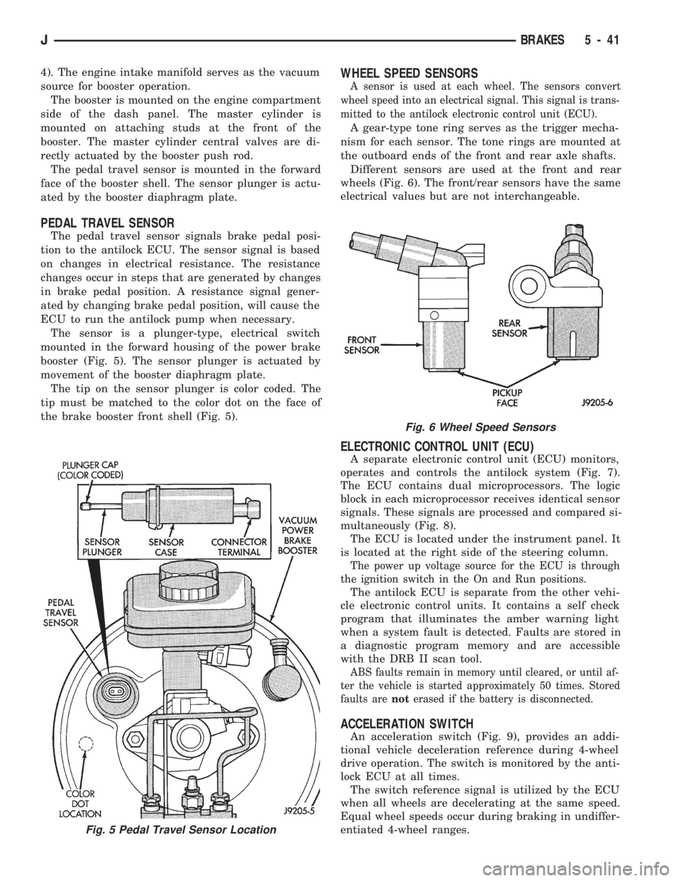
The sensor is a plunger-type, electrical switch
mounted in the forward housing of the power brake
booster (Fig. 5). The sensor plunger is actuated by
movement of the booster diaphragm plate.
The tip on the sensor plunger is color coded. The
tip must be matched to the color dot on the face of
the brake booster front shell (Fig. 5).
WHEEL SPEED SENSORS
A sensor is used at each wheel. The sensors convert
wheel speed into an electrical signal. This signal is trans-
mitted to the antilock electronic control unit (ECU).
A gear-type tone ring serves as the trigger mecha-
nism for each sensor. The tone rings are mounted at
the outboard ends of the front and rear axle shafts.
Different sensors are used at the front and rear
wheels (Fig. 6). The front/rear sensors have the same
electrical values but are not interchangeable.
ELECTRONIC CONTROL UNIT (ECU)
A separate electronic control unit (ECU) monitors,
operates and controls the antilock system (Fig. 7).
The ECU contains dual microprocessors. The logic
block in each microprocessor receives identical sensor
signals. These signals are processed and compared si-
multaneously (Fig. 8).
The ECU is located under the instrument panel. It
is located at the right side of the steering column.
The power up voltage source for the ECU is through
the ignition switch in the On and Run positions.
The antilock ECU is separate from the other vehi-
cle electronic control units. It contains a self check
program that illuminates the amber warning light
when a system fault is detected. Faults are stored in
a diagnostic program memory and are accessible
with the DRB II scan tool.
ABS faults remain in memory until cleared, or until af-
ter the vehicle is started approximately 50 times. Stored
faults arenoterased if the battery is disconnected.
ACCELERATION SWITCH
An acceleration switch (Fig. 9), provides an addi-
tional vehicle deceleration reference during 4-wheel
drive operation. The switch is monitored by the anti-
lock ECU at all times.
The switch reference signal is utilized by the ECU
when all wheels are decelerating at the same speed.
Equal wheel speeds occur during braking in undiffer-
entiated 4-wheel ranges.
Fig. 5 Pedal Travel Sensor Location
Fig. 6 Wheel Speed Sensors
JBRAKES 5 - 41
Page 208 of 1784
(5) Install lever cover. Secure cover with new riv-
ets, or original attaching screws.
(6) Raise vehicle.
(7) Connect tensioner to lever with retaining pin
and E-clip.
(8) Install nuts attaching lever support plate to le-
ver screws.
(9) Adjust parking brakes. Refer to procedure in
this section.
PARKING BRAKE CABLE TENSIONER
REPLACEMENT (XJ)
(1) Raise vehicle.
(2) Remove adjuster nut from tensioner rod. Secure
equalizer and cables to nearby chassis component
with wire.
(3) Remove nuts attaching lever assembly to sup-
port plate and floorpan.
(4) Lower vehicle.
(5) Remove console components and lever assembly
cover.
(6) Remove lever and tensioner assembly.
(7) Move cover and boot for access to tensioner re-
taining pin.
(8) Remove E-clip and pin that attach tensioner to
lever arm (Fig. 3).
(9) Remove tensioner from cover.
(10) Transfer boot to new tensioner if necessary.
(11) Attach tensioner to lever arm with pin and
E-clip.
(12) Verify that E-clip is fully engaged in pin (Fig.
3).(13) Align cover and seal on lever flange.
(14) Verify that tensioner boot is seated in cover
(Fig. 5).
(15) Install assembled lever and tensioner in floor-
pan.
(16) Install necessary console components.
(17) Adjust parking brakes as described in this sec-
tion.
PARKING BRAKE PEDAL REMOVAL (YJ)
(1) Raise vehicle.
(2) Loosen equalizer nuts until front cable is slack
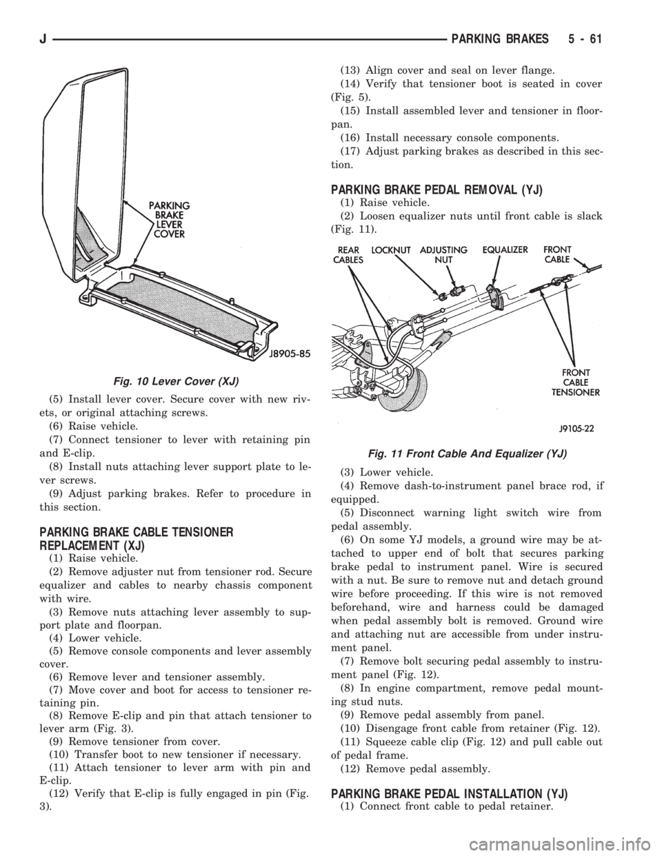
(Fig. 11).
(3) Lower vehicle.
(4) Remove dash-to-instrument panel brace rod, if
equipped.
(5) Disconnect warning light switch wire from
pedal assembly.
(6) On some YJ models, a ground wire may be at-
tached to upper end of bolt that secures parking
brake pedal to instrument panel. Wire is secured
with a nut. Be sure to remove nut and detach ground
wire before proceeding. If this wire is not removed
beforehand, wire and harness could be damaged
when pedal assembly bolt is removed. Ground wire
and attaching nut are accessible from under instru-
ment panel.
(7) Remove bolt securing pedal assembly to instru-
ment panel (Fig. 12).
(8) In engine compartment, remove pedal mount-
ing stud nuts.
(9) Remove pedal assembly from panel.
(10) Disengage front cable from retainer (Fig. 12).
(11) Squeeze cable clip (Fig. 12) and pull cable out
of pedal frame.
(12) Remove pedal assembly.
PARKING BRAKE PEDAL INSTALLATION (YJ)
(1) Connect front cable to pedal retainer.
Fig. 10 Lever Cover (XJ)
Fig. 11 Front Cable And Equalizer (YJ)
JPARKING BRAKES 5 - 61
Page 209 of 1784
(2) Position pedal assembly on panel and install
mounting stud nuts and pedal-to-dash bolt.
(3) Install ground wire on upper end of pedal-to-
dash bolt and secure wire with attaching nut.
(4) Connect warning light switch wire to pedal
connector.
(5) Install dash-to-instrument panel brace rod, if
equipped.
(6) Raise vehicle and adjust brake cables. Refer to
procedure in Service Adjustment section.
PARKING BRAKE REAR CABLE REPLACEMENT (XJ)
(1) Raise vehicle and loosen equalizer nuts until
rear cables are slack.
(2) Disengage cable from equalizer and remove ca-
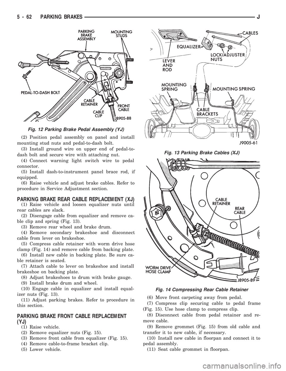
ble clip and spring (Fig. 13).
(3) Remove rear wheel and brake drum.
(4) Remove secondary brakeshoe and disconnect
cable from lever on brakeshoe.
(5) Compress cable retainer with worm drive hose
clamp (Fig. 14) and remove cable from backing plate.
(6) Install new cable in backing plate. Be sure ca-
ble retainer is seated.
(7) Attach cable to lever on brakeshoe and install
brakeshoe on backing plate.
(8) Adjust brakeshoes to drum with brake gauge.
(9) Install brake drum and wheel.
(10) Engage cable in equalizer and install equal-
izer nuts (Fig. 13).
(11) Adjust parking brakes. Refer to procedure in
this section.
PARKING BRAKE FRONT CABLE REPLACEMENT
(YJ)
(1) Raise vehicle.
(2) Remove equalizer nuts (Fig. 15).
(3) Remove front cable from equalizer (Fig. 15).
(4) Remove cable-to-frame bracket clip.
(5) Lower vehicle.(6) Move front carpeting away from pedal.
(7) Compress clip securing cable to pedal frame
(Fig. 15). Use hose clamp to compress clip.
(8) Disconnect cable from pedal retainer and re-
move cable.
(9) Remove grommet (Fig. 15) from old cable and
transfer it to new cable, if necessary.
(10) Install new cable in floorpan and connect it to
pedal assembly.
(11) Seat cable grommet in floorpan.
Fig. 12 Parking Brake Pedal Assembly (YJ)
Fig. 13 Parking Brake Cables (XJ)
Fig. 14 Compressing Rear Cable Retainer
5 - 62 PARKING BRAKESJ
Page 212 of 1784
BRAKE PEDAL AND BRAKELIGHT SWITCH
INDEX
page page
Brake Pedal Installation.................... 66
Brake Pedal Removal..................... 65
Brake Pedal Service...................... 65
Brakelight Switch Adjustment................ 66Brakelight Switch Installation................ 66
Brakelight Switch Removal................. 66
General Information....................... 65
GENERAL INFORMATION
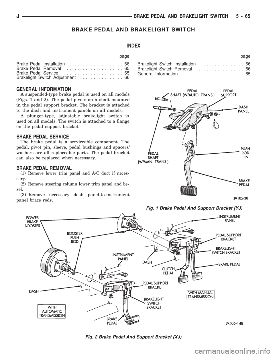
A suspended-type brake pedal is used on all models
(Figs. 1 and 2). The pedal pivots on a shaft mounted
in the pedal support bracket. The bracket is attached
to the dash and instrument panels on all models.
A plunger-type, adjustable brakelight switch is
used on all models. The switch is attached to a flange
on the pedal support bracket.
BRAKE PEDAL SERVICE
The brake pedal is a serviceable component. The
pedal, pivot pin, sleeve, pedal bushings and spacers/
washers are all replaceable parts. The pedal bracket
can also be replaced when necessary.
BRAKE PEDAL REMOVAL
(1) Remove lower trim panel and A/C duct if neces-
sary.
(2) Remove steering column lower trim panel and be-
zel.
(3) Remove necessary dash panel-to-instrument
panel brace rods.
Fig. 1 Brake Pedal And Support Bracket (YJ)
Fig. 2 Brake Pedal And Support Bracket (XJ)
JBRAKE PEDAL AND BRAKELIGHT SWITCH 5 - 65