1994 JEEP CHEROKEE gas type
[x] Cancel search: gas typePage 963 of 1784
line. You may encounter fuels containing 3 percent
or more methanol along with other alcohols called co-
solvents.
Problems that are the result of using methanol/gas-
oline blends are not the responsibility of Chrysler
Corporation. They may not be covered by the vehicle
warranty.
MTBE/ETBE
Gasoline and MTBE (Methyl Tertiary Butyl Ether)
blends are a mixture of unleaded gasoline and up to
15 percent MTBE. Gasoline and ETBE (Ethyl Ter-
tiary Butyl Ether) are blends of gasoline and up to
17 percent ETBE. Gasoline blended with MTBE or
ETBE may be used in your vehicle.CLEAN AIR GASOLINE
Many gasolines are now being blended that con-
tribute to cleaner air, especially in those areas of the
country where air pollution levels are high. These
new blends provide a cleaner burning fuel and some
are referred to asReformulated Gasoline.
In areas of the country where carbon monoxide lev-
els are high, gasolines are being treated with oxy-
genated materials such as MTBE, ETBE and
ethanol.
Chrysler Corporation supports these efforts toward
cleaner air and recommends that you use these gas-
olines as they become available.
FUEL DELIVERY SYSTEM
INDEX
page page
Fuel Filter............................... 8
Fuel Pressure Leak Down Test............... 7
Fuel Pressure Release Procedure............. 5
Fuel Pump Capacity Test................... 7
Fuel Pump Electrical Control................. 5Fuel Pump Module........................ 2
Fuel System Pressure Test.................. 5
Fuel Tubes/Lines/Hoses and Clamps........... 9
Quick-Connect Fittings..................... 9
FUEL PUMP MODULE
The fuel pump module is installed in the top of the
fuel tank. The fuel pump module contains the follow-
ing components:
²Electric fuel pump
²Fuel pump reservoir
²In-tank fuel filter
²Fuel gauge sending unit
²Fuel supply and return tube connections
The fuel pump used on all vehicles is a gear/rotor
type pump. It is driven by a permanent magnet 12
volt electric motor that is immersed in the fuel tank.
The electrical pump is integral with the fuel sender
unit. The pump/sender assembly is installed inside
the fuel tank.
The fuel pump has a check valve at the outlet end
that consists of a ball held against a seat by force ap-
plied from a spring. When the pump is operating,
fuel pressure overcomes spring pressure and forces
the ball off its seat, allowing fuel to flow. When the
pump is not operating, spring pressure forces the ball
back against the seat preventing fuel backflow
through the pump.
Fuel system pressure is maintained at approxi-
mately 214 kPa (31 psi). This is when the pump is
operating and vacuum is supplied to the fuel pres-
sure regulator. If vacuum is not supplied to the pres-
sure regulator, fuel pressure will be approximately
55-69 kPa (8-10 psi) higher. This may be due to a
broken or clogged vacuum line. When the fuel pumpis not operating, system fuel pressure of 131-269 kPa
(19-39 psi) is maintained. This is done by the fuel
pump outlet check valve and the vacuum assisted
fuel pressure regulator.
REMOVALÐXJ MODELS
The fuel pump/gauge sender unit assembly can be
removed from the fuel tank without removing the
tank from the vehicle.
WARNING: THE FUEL SYSTEM IS UNDER A CON-
STANT PRESSURE (EVEN WITH THE ENGINE OFF).
BEFORE SERVICING THE FUEL PUMP MODULE,
THE FUEL SYSTEM PRESSURE MUST BE RE-
LEASED. REFER TO THE FUEL PRESSURE RE-
LEASE PROCEDURE IN THIS GROUP.
WARNING: EXTINGUISH ALL TOBACCO SMOKING
PRODUCTS BEFORE SERVICING THE FUEL SYS-
TEM. KEEP OPEN FLAME AWAY FROM FUEL SYS-
TEM COMPONENTS.
(1) Remove fuel filler cap. Perform the Fuel Pres-
sure Release Procedure as outlined in this group.
(2) Disconnect negative battery cable.
(3) Using an approved portable gasoline siphon/
storage tank, drain fuel tank until fuel level is below
one quarter (1/4) full.
(4) Raise and support vehicle.
14 - 2 FUEL SYSTEMJ
Page 973 of 1784
FUEL TANKS
INDEX
page page
Fuel Gauge Sending Unit.................. 15
Fuel Tank.............................. 12
Fuel Tank Filler Tube Cap................. 12
Fuel Tank Pressure Relief/Rollover Valve...... 15General Information....................... 12
Heat Shields............................ 12
No-Lead Fuel Tank Filler Tube.............. 12
GENERAL INFORMATION
All vehicles pass a full 360 degree rollover test
without fuel leakage. To accomplish this, fuel and
vapor flow controls are required for all fuel tank con-
nections.
All models are equipped with a pressure relief/roll-
over valve mounted in the top of the fuel pump mod-
ule. The return line from the fuel pump to the fuel
tank contains a one-way check valve.
An evaporative control system prevents raw fuel
vapor from escaping into the atmosphere. Fuel va-
pors from the fuel tank are collected in the EVAP
canister. When the engine is operating, the vapors
are drawn into the intake manifold to be used in
combustion. Refer to Group 25, Emission Control
System for more information.
Inspect all hose/tube connections for completeness.
Be sure that leaks are not present. Replace any hose
that is cracked, scuffed, swelled, has rubbed against
other vehicle components or shows any other sign of
wear that could lead to failure. If it is necessary to
replace a hose, only hose marked EFM/EFI may be
used.
When installing hoses, be sure that they are routed
away from contact with other vehicle components.
The hose clamps used on fuel injected vehicles are
of a special rolled edge construction to prevent the
edge of the clamp from cutting into the hose. Only
these rolled edge type clamps may be used on this
system. Other types of clamps may cut into the hoses
and cause high pressure fuel leaks.
NO-LEAD FUEL TANK FILLER TUBE
All vehicles are designed to operate using Un-
leaded fuels. The diameter of the opening in the fuel
tank filler neck is sized to only accept unleaded fuel
nozzles. Gasoline station pumps for unleaded and
leaded fuels have different size nozzles. Leaded fuel
nozzles are larger in diameter than unleaded nozzles.
The fuel tank filler neck opening is also equipped
with a deflector, which the smaller unleaded nozzle
pushes back upon entering the filler neck. The de-
flector will prevent the larger diameter leaded fuel
nozzles from entering the filler neck and will deflect
fuel away from the filler neck. This happens if filling
of the tank with leaded fuel is attempted.
A label is attached to the instrument panel under
the fuel gauge that reads UNLEADED FUEL ONLY
as a reminder to the driver. A similar label is located
near the fuel tank filler.
FUEL TANK FILLER TUBE CAP
The loss of any fuel or vapor out of the filler neck
is prevented by the use of a safety filler cap. This
will release only under pressure of 10.9 to 13.45 kPa
(1.58 to 1.95 psi). The vacuum release is between .97
and 2.0 kPa (.14 and .29 psi). This cap must be re-
placed by a similar unit if replacement is necessary.
CAUTION: Remove the fuel tank filler tube cap prior
to removing or repairing fuel lines to relieve fuel
tank pressure.
HEAT SHIELDS
The sheet metal heat shields may have to be re-
moved when servicing the fuel tank, fuel lines or va-
por vent line. The heat shields must be installed to
protect the lines and tank from the heat of the ex-
haust system. Refer to Group 11, Exhaust System
and Intake Manifold for proper installation.
FUEL TANK
WARNING: THE FUEL SYSTEM IS UNDER CON-
STANT FUEL PRESSURE (EVEN WITH THE ENGINE
OFF) OF APPROXIMATELY 131-269 KPA (19-39
PSI). THIS PRESSURE MUST BE RELEASED BE-
FORE SERVICING FUEL TANK.
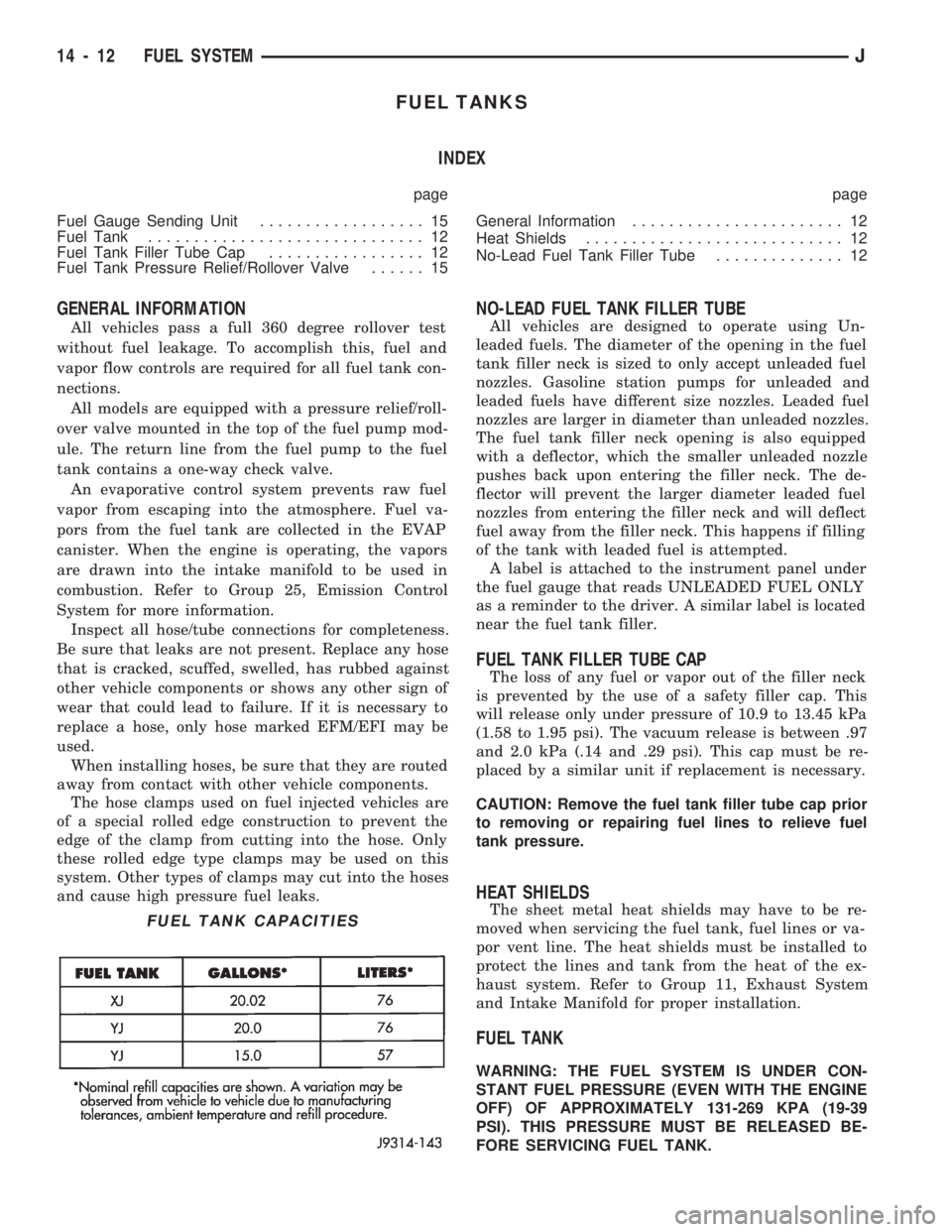
FUEL TANK CAPACITIES
14 - 12 FUEL SYSTEMJ
Page 1177 of 1784
30RH/32RH AUTOMATIC TRANSMISSION
INDEX
page page
General Information....................... 66
Parts Interchangeability.................... 66
Recommended Fluid...................... 66
Specifications and Band Adjustments......... 66Torque Converter........................ 66
Transmission Application................... 66
Transmission Controls and Components....... 66
Transmission Identification.................. 66
GENERAL INFORMATION
TRANSMISSION APPLICATION
Chrysler 30RH and 32RH automatic transmissions
are used in XJ/YJ models. Both transmissions are
three speed, automatics with a gear-type oil pump,
two clutches and bands and a planetary gear system
(Fig. 1). The 30RH is used with 2.5L engines and the
32RH is used with 4.0L engines.
TORQUE CONVERTER
A three element, torque converter is used for all
applications. The converter consists of the impeller,
stator, and turbine.
The converter used with all 30RH/32RH transmis-
sions is equipped with a converter clutch. The clutch
is engaged by an electrical solenoid and mechanical
clutch module on the valve body. The solenoid is op-
erated by the powertrain control module.
The impeller is connected to the engine crankshaft
through the front cover which is welded to the impel-
ler. The turbine is splined to the transmission input
shaft and the stator is splined to the transmission re-
action shaft.
The torque converter is a welded assembly and is
not a repairable component. The converter is serviced
as an assembly.
RECOMMENDED FLUID
The recommended (and preferred) fluid for 30RH/
32RH transmissions is Mopar ATF Plus, Type 7176.
Mopar Dexron II can be used but only if ATF Plus
is not available.
Transmission fluid capacity is approximately 17
pints (7.9 liters). This is the approximate amount of
fluid required to fill the transmission and torque con-
verter after overhaul.
TRANSMISSION IDENTIFICATION
The transmission identification numbers are
stamped on the left side of the case just above the oil
pan gasket surface (Fig. 2). The first set of numbers
is the transmission part number. The next set of code
numbers set is the date of build. The final set of code
numbers represents the transmission serial number.
SPECIFICATIONS AND BAND ADJUSTMENTS
Service specifications and torque values are located
at the end of this group. Refer to the specifications
during service operations.
The band adjustment specifications for 1994
transmissions are different. Refer to the front
and rear band adjustment procedures in the In-
Vehicle Service section for details.
PARTS INTERCHANGEABILITY
The 1994 version of the 30RH (A904) transmission
is similar to previous models in appearance only. The
current 30RH is quite different and interchanging
new/old parts is definitely not recommended. Differ-
ent component dimensions, fluid passages, input/out-
put shafts, cases, bands, valve bodies and governor
assemblies are just a few of the changed items. The
32RH transmission is also different from previous
models and the same recommendations apply here as
well.
CAUTION: On YJ models with a 2.5L engine and
30RH transmission, special bolts are used to attach
the driveplate to the crankshaft. These bolts have a
smaller hex head for torque converter clearance.
DO NOT interchange these bolts with similar size
bolts for any reason.
TRANSMISSION CONTROLS AND COMPONENTS
The transmission hydraulic control system per-
forms five basic functions, which are:
²pressure supply
²pressure regulation
²flow control
²clutch/band apply and release
²lubrication
Pressure Supply And Regulation
The oil pump generates the fluid working pressure
needed for operation and lubrication. The pump is
driven by the torque converter. The converter is con-
nected to the engine crankshaft through the drive-
plate.
The pressure regulator valve maintains operating
(line) pressure. The regulator valve is located in the
valve body. The amount of line pressure developed is
21 - 66 30RH/32RH AUTOMATIC TRANSMISSIONJ
Page 1211 of 1784
OIL FILTER REPLACEMENT
(1) Raise vehicle.
(2) Remove oil pan and drain fluid.
(3) Remove filter screws and remove oil filter (Fig.
9).
(4) Position new filter on valve body and install fil-
ter screws finger tight.
(5) Tighten filter screws to 4 Nzm (35 in. lbs.) with
inch pound torque wrench.
(6) Position new gasket on oil pan and install pan
on transmission. Tighten pan bolts to 17 Nzm (150 in.
lbs.) torque.
(7) Lower vehicle.
(8) Refill transmission with Mopar ATF Plus, Type
7176. Mopar Dexron II can be used if ATF Plus is not
readily available.
VALVE BODY REMOVAL
(1) Raise vehicle.
(2) Remove oil pan and drain fluid.
(3) Disconnect gearshift and throttle linkage at
transmission levers.
(4) Loosen clamp bolts and remove throttle and
manual valve levers from manual valve shaft.
(5) Disconnect park/neutral position switch wires
and remove switch and switch seal.
(6) Remove valve body oil filter.(7) Remove valve body attaching screws. Lower
valve body slightly and remove accumulator piston
and spring (Fig. 10). Rotate valve body down and
away from case. Pull it forward to disengage park
rod and remove valve body.
(8) Position valve body on bench or on repair stand
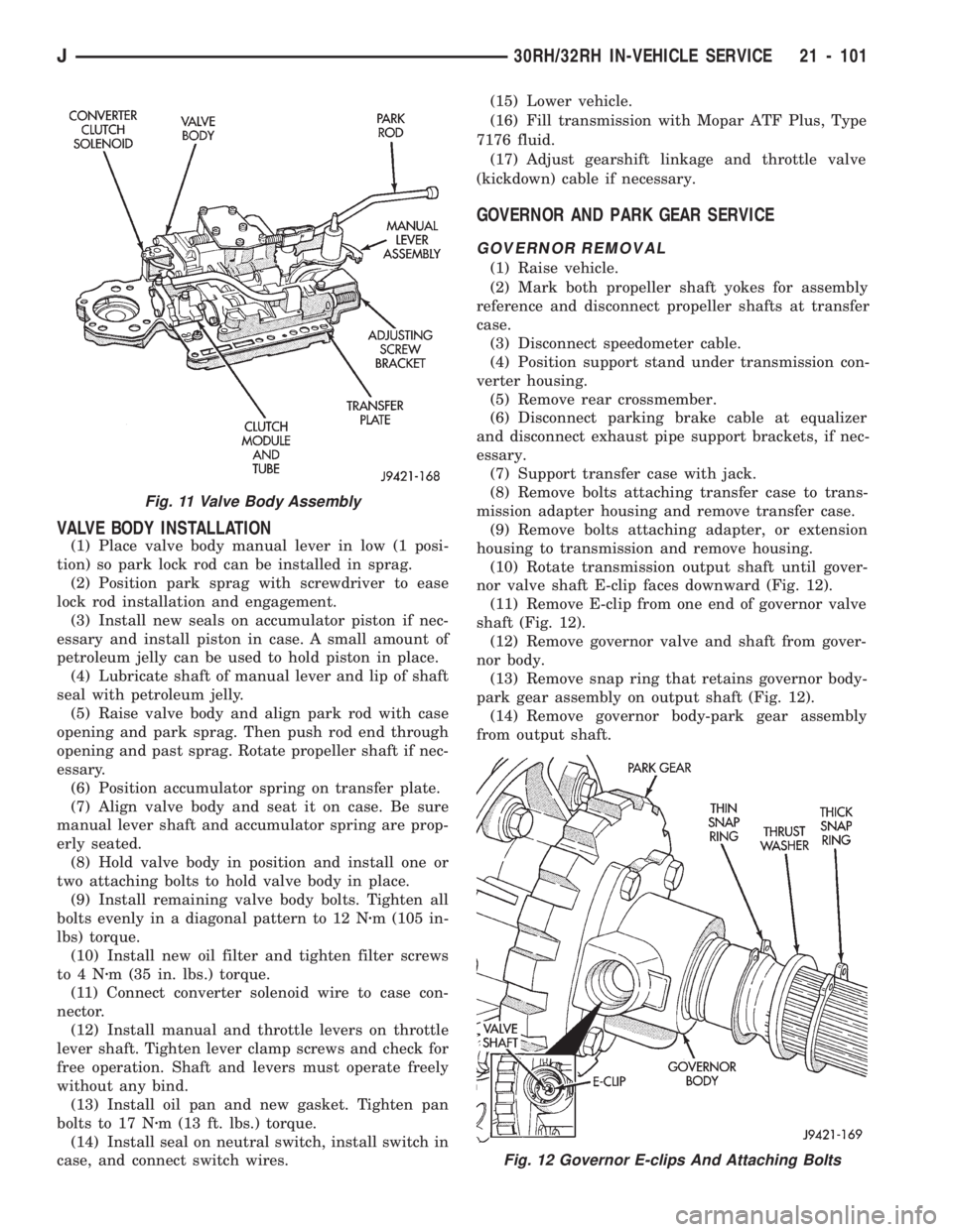
for disassembly, cleaning and inspection (Fig. 11).
VALVE BODY SERVICE
The valve body can be disassembled for cleaning
and inspection of the individual components. Valve
body service procedures are detailed in the overhaul
section.
The only serviceable valve body components are:
²park lock rod and E-clip
²switch valve and spring
²pressure adjusting screw bracket
²throttle valve lever
²manual lever
²manual lever shaft seal, washer, E-clip and detent
ball
²fluid filter
²converter clutch solenoid
The remaining valve body components are serviced
only as part of a complete valve body assembly.
Fig. 9 Oil Filter Screw Locations
Fig. 10 Accumulator Piston And Spring
Fig. 8 Rear Band Lever And Adjusting Screw
Location
21 - 100 30RH/32RH IN-VEHICLE SERVICEJ
Page 1212 of 1784
VALVE BODY INSTALLATION
(1) Place valve body manual lever in low (1 posi-
tion) so park lock rod can be installed in sprag.
(2) Position park sprag with screwdriver to ease
lock rod installation and engagement.
(3) Install new seals on accumulator piston if nec-
essary and install piston in case. A small amount of
petroleum jelly can be used to hold piston in place.
(4) Lubricate shaft of manual lever and lip of shaft
seal with petroleum jelly.
(5) Raise valve body and align park rod with case
opening and park sprag. Then push rod end through
opening and past sprag. Rotate propeller shaft if nec-
essary.
(6) Position accumulator spring on transfer plate.
(7) Align valve body and seat it on case. Be sure
manual lever shaft and accumulator spring are prop-
erly seated.
(8) Hold valve body in position and install one or
two attaching bolts to hold valve body in place.
(9) Install remaining valve body bolts. Tighten all
bolts evenly in a diagonal pattern to 12 Nzm (105 in-
lbs) torque.
(10) Install new oil filter and tighten filter screws
to4Nzm (35 in. lbs.) torque.
(11) Connect converter solenoid wire to case con-
nector.
(12) Install manual and throttle levers on throttle
lever shaft. Tighten lever clamp screws and check for
free operation. Shaft and levers must operate freely
without any bind.
(13) Install oil pan and new gasket. Tighten pan
bolts to 17 Nzm (13 ft. lbs.) torque.
(14) Install seal on neutral switch, install switch in
case, and connect switch wires.(15) Lower vehicle.
(16) Fill transmission with Mopar ATF Plus, Type
7176 fluid.
(17) Adjust gearshift linkage and throttle valve
(kickdown) cable if necessary.
GOVERNOR AND PARK GEAR SERVICE
GOVERNOR REMOVAL
(1) Raise vehicle.
(2) Mark both propeller shaft yokes for assembly
reference and disconnect propeller shafts at transfer
case.
(3) Disconnect speedometer cable.
(4) Position support stand under transmission con-
verter housing.
(5) Remove rear crossmember.
(6) Disconnect parking brake cable at equalizer
and disconnect exhaust pipe support brackets, if nec-
essary.
(7) Support transfer case with jack.
(8) Remove bolts attaching transfer case to trans-
mission adapter housing and remove transfer case.
(9) Remove bolts attaching adapter, or extension
housing to transmission and remove housing.
(10) Rotate transmission output shaft until gover-
nor valve shaft E-clip faces downward (Fig. 12).
(11) Remove E-clip from one end of governor valve
shaft (Fig. 12).
(12) Remove governor valve and shaft from gover-
nor body.
(13) Remove snap ring that retains governor body-
park gear assembly on output shaft (Fig. 12).
(14) Remove governor body-park gear assembly
from output shaft.
Fig. 12 Governor E-clips And Attaching Bolts
Fig. 11 Valve Body Assembly
J30RH/32RH IN-VEHICLE SERVICE 21 - 101
Page 1213 of 1784
GOVERNOR DISASSEMBLY
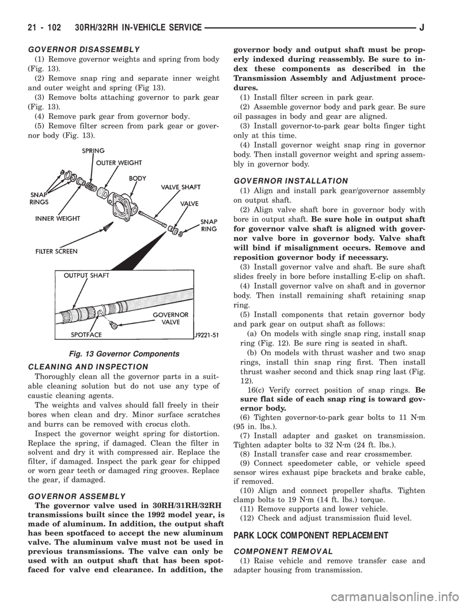
(1) Remove governor weights and spring from body
(Fig. 13).
(2) Remove snap ring and separate inner weight
and outer weight and spring (Fig 13).
(3) Remove bolts attaching governor to park gear
(Fig. 13).
(4) Remove park gear from governor body.
(5) Remove filter screen from park gear or gover-
nor body (Fig. 13).
CLEANING AND INSPECTION
Thoroughly clean all the governor parts in a suit-
able cleaning solution but do not use any type of
caustic cleaning agents.
The weights and valves should fall freely in their
bores when clean and dry. Minor surface scratches
and burrs can be removed with crocus cloth.
Inspect the governor weight spring for distortion.
Replace the spring, if damaged. Clean the filter in
solvent and dry it with compressed air. Replace the
filter, if damaged. Inspect the park gear for chipped
or worn gear teeth or damaged ring grooves. Replace
the gear, if damaged.
GOVERNOR ASSEMBLY
The governor valve used in 30RH/31RH/32RH
transmissions built since the 1992 model year, is
made of aluminum. In addition, the output shaft
has been spotfaced to accept the new aluminum
valve. The aluminum valve must not be used in
previous transmissions. The valve can only be
used with an output shaft that has been spot-
faced for valve end clearance. In addition, thegovernor body and output shaft must be prop-
erly indexed during reassembly. Be sure to in-
dex these components as described in the
Transmission Assembly and Adjustment proce-
dures.
(1) Install filter screen in park gear.
(2) Assemble governor body and park gear. Be sure
oil passages in body and gear are aligned.
(3) Install governor-to-park gear bolts finger tight
only at this time.
(4) Install governor weight snap ring in governor
body. Then install governor weight and spring assem-
bly in governor body.
GOVERNOR INSTALLATION
(1) Align and install park gear/governor assembly
on output shaft.
(2) Align valve shaft bore in governor body with
bore in output shaft.Be sure hole in output shaft
for governor valve shaft is aligned with gover-
nor valve bore in governor body. Valve shaft
will bind if misalignment occurs. Remove and
reposition governor body if necessary.
(3) Install governor valve and shaft. Be sure shaft
slides freely in bore before installing E-clip on shaft.
(4) Install governor valve on shaft and in governor
body. Then install remaining shaft retaining snap
ring.
(5) Install components that retain governor body
and park gear on output shaft as follows:
(a) On models with single snap ring, install snap
ring (Fig. 12). Be sure ring is seated in shaft.
(b) On models with thrust washer and two snap
rings, install thin snap ring first. Then install
thrust washer second and thick snap ring last (Fig.
12).
16(c) Verify correct position of snap rings.Be
sure flat side of each snap ring is toward gov-
ernor body.
(6) Tighten governor-to-park gear bolts to 11 Nzm
(95 in. lbs.).
(7) Install adapter and gasket on transmission.
Tighten adapter bolts to 32 Nzm (24 ft. lbs.).
(8) Install transfer case and rear crossmember.
(9) Connect speedometer cable, or vehicle speed
sensor wires exhaust pipe brackets and brake cable,
if removed.
(10) Align and connect propeller shafts. Tighten
clamp bolts to 19 Nzm (14 ft. lbs.) torque.
(11) Remove supports and lower vehicle.
(12) Check and adjust transmission fluid level.
PARK LOCK COMPONENT REPLACEMENT
COMPONENT REMOVAL
(1) Raise vehicle and remove transfer case and
adapter housing from transmission.
Fig. 13 Governor Components
21 - 102 30RH/32RH IN-VEHICLE SERVICEJ
Page 1229 of 1784
OVERHAUL SERVICE INFORMATION
Inspect the transmission bushings during overhaul.
Bushing condition is important as severely worn, or
scored bushings contribute to low pressures, clutch
slip and accelerated wear of other components.How-
ever, do not replace bushings as a matter of
course. Replace bushings only when they are
actually worn, or scored.
Use recommended tools to replace bushings. The
tools are sized and designed to remove, install and
seat bushings correctly. The bushing replacement
tools are included in Bushing Tool Set C-3887-B. The
tool set is manufactured by Miller Tool Co. and is
available through the dealer tool program.
Pre-sized service bushings are available for replace-
ment purposes. Only the sun gear bushings are not
serviced. Low cost of the sun gear assembly makes it
easier to simply replace the gear and bushings as an
assembly.
Heli-Coil inserts are recommended for repairing
damaged, stripped or worn threads in aluminum
parts. These inserts are available from most automo-
tive jobbers. Stainless steel inserts are preferred.
The use of crocus cloth is permissible where neces-
sary. When used on valves, use care to avoid round-
ing off sharp edges. Sharp edges are vital as they
prevent foreign matter from getting between the
valve and valve bore.
Do not reuse oil seals, gaskets, seal rings, or O-
rings during overhaul. Replace these parts as a mat-
ter of course. Also do not reuse snap rings or E-clips
that are bent or distorted. Replace these parts as
well.
Lubricate transmission parts with Mopar ATF
Plus, Type 7176 transmission fluid during overhaul
and assembly.Use petroleum jelly to hold parts like thrust wash-
ers in place during assembly. Use Ru-Glyde, Door
Eze, or similar products to lubricate piston seals and
O-rings to ease installation. Petroleum jelly can also
be used to prelubricate parts during reassembly if de-
sired.
TRANSMISSION CASE CLEANING AND
INSPECTION
Clean the case in a solvent tank. Flush the case
bores and fluid passages thoroughly with solvent.
Dry the case and all fluid passages with compressed
air. Be sure all solvent is removed from the case and
that all fluid passages are clear.
Do not use shop towels or rags to dry the case
(or any other transmission component) unless
they are made from lint-free materials. Lint will
readily adhere to case surfaces and transmission
components and will circulate throughout the
transmission after assembly. A sufficient quan-
tity of lint can block fluid passages and interfere
with valve body operation.
Inspect the case for cracks, porous spots, worn
bores, or damaged threads. Damaged threads can be
repaired with Helicoil thread inserts. However, the
case will have to be replaced if it exhibits any type of
damage or wear.
Lubricate the front band adjusting screw threads
with petroleum jelly and thread the screw part-way
into the case. Be sure the screw turns freely.
Remount the case in a repair stand after cleaning
and inspection.
OVERRUNNING CLUTCHÐLOW-REVERSE
DRUMÐREAR SUPPORT OVERHAUL
DISASSEMBLING OVERRUNNING CLUTCH/
LOW-REVERSE DRUM
If the clutch assembly came out with the low-re-
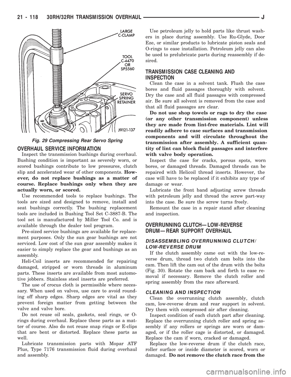
verse drum, thread two clutch cam bolts into the
cam. Then lift the cam out of the drum with the bolts
(Fig. 30). Rotate the cam back and forth to ease re-
moval if necessary. Remove the clutch roller and
spring assembly from the race afterward.
CLEANING AND INSPECTION
Clean the overrunning clutch assembly, clutch
cam, low-reverse drum and rear support in solvent.
Dry them with compressed air after cleaning.
Inspect condition of each clutch part after cleaning.
Replace the overrunning clutch roller and spring as-
sembly if any rollers or springs are worn or dam-
aged, or if the roller cage is distorted, or damaged.
Replace the cam if worn, cracked or damaged.
Replace the low-reverse drum if the clutch race,
roller surface or inside diameter is scored, worn or
damaged.Do not remove the clutch race from the
Fig. 29 Compressing Rear Servo Spring
21 - 118 30RH/32RH TRANSMISSION OVERHAULJ
Page 1252 of 1784
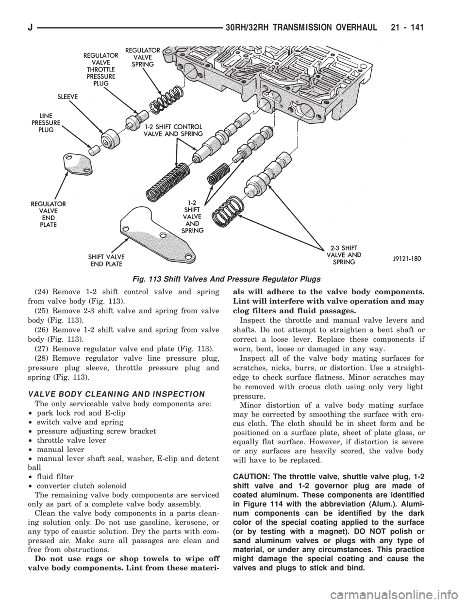
(24) Remove 1-2 shift control valve and spring
from valve body (Fig. 113).
(25) Remove 2-3 shift valve and spring from valve
body (Fig. 113).
(26) Remove 1-2 shift valve and spring from valve
body (Fig. 113).
(27) Remove regulator valve end plate (Fig. 113).
(28) Remove regulator valve line pressure plug,
pressure plug sleeve, throttle pressure plug and
spring (Fig. 113).
VALVE BODY CLEANING AND INSPECTION
The only serviceable valve body components are:
²park lock rod and E-clip
²switch valve and spring
²pressure adjusting screw bracket
²throttle valve lever
²manual lever
²manual lever shaft seal, washer, E-clip and detent
ball
²fluid filter
²converter clutch solenoid
The remaining valve body components are serviced
only as part of a complete valve body assembly.
Clean the valve body components in a parts clean-
ing solution only. Do not use gasoline, kerosene, or
any type of caustic solution. Dry the parts with com-
pressed air. Make sure all passages are clean and
free from obstructions.
Do not use rags or shop towels to wipe off
valve body components. Lint from these materi-als will adhere to the valve body components.
Lint will interfere with valve operation and may
clog filters and fluid passages.
Inspect the throttle and manual valve levers and
shafts. Do not attempt to straighten a bent shaft or
correct a loose lever. Replace these components if
worn, bent, loose or damaged in any way.
Inspect all of the valve body mating surfaces for
scratches, nicks, burrs, or distortion. Use a straight-
edge to check surface flatness. Minor scratches may
be removed with crocus cloth using only very light
pressure.
Minor distortion of a valve body mating surface
may be corrected by smoothing the surface with cro-
cus cloth. The cloth should be in sheet form and be
positioned on a surface plate, sheet of plate glass, or
equally flat surface. However, if distortion is severe
or any surfaces are heavily scored, the valve body
will have to be replaced.
CAUTION: The throttle valve, shuttle valve plug, 1-2
shift valve and 1-2 governor plug are made of
coated aluminum. These components are identified
in Figure 114 with the abbreviation (Alum.). Alumi-
num components can be identified by the dark
color of the special coating applied to the surface
(or by testing with a magnet). DO NOT polish or
sand aluminum valves or plugs with any type of
material, or under any circumstances. This practice
might damage the special coating and cause the
valves and plugs to stick and bind.
Fig. 113 Shift Valves And Pressure Regulator Plugs
J30RH/32RH TRANSMISSION OVERHAUL 21 - 141