1994 JEEP CHEROKEE check engine light
[x] Cancel search: check engine lightPage 252 of 1784

Leakage Test. Do this if it is certain that coolant is
being lost and no leaks can be detected.
²Drops Slowly: Shows a small leak or seepage is oc-
curring. Examine all connections for seepage or
slight leakage with a flashlight. Inspect the radiator,
hoses, gasket edges and heater. Seal any small leak
holes with a Sealer Lubricant or equivalent. Repair
leak holes and reinspect the system with pressure
applied.
²Drops Quickly: Shows that a serious leakage is oc-
curring. Examine the system for serious external
leakage. If no leaks are visible, inspect for internal
leakage. Large radiator leak holes should be repaired
by a reputable radiator repair shop.
INTERNAL LEAKAGE INSPECTION
Remove the oil pan drain plug and drain a small
amount of engine oil. Coolant, being heavier will
drain first, or operate engine to churn oil, then ex-
amine dipstick for water globules. Inspect the trans-
mission dipstick for water globules. Inspect the
transmission fluid cooler for leakage. Operate the en-
gine without the pressure cap on the radiator until
thermostat opens.
Attach a Pressure Tester to the filler neck. If pres-
sure builds up quickly, a leak exists as result of a
faulty cylinder head gasket or crack in the engine.
Repair as necessary.
WARNING: DO NOT ALLOW PRESSURE TO EX-
CEED 124 KPA (18 PSI). TURN THE ENGINE OFF.
TO RELEASE THE PRESSURE, ROCK THE TESTER
FROM SIDE TO SIDE. WHEN REMOVING THE
TESTER, DO NOT TURN THE TESTER MORE THAN
1/2 TURN IF THE SYSTEM IS UNDER PRESSURE.
If there is no immediate pressure increase, pump
the Pressure Tester until the indicated pressure is
within the system range. Vibration of the gauge
pointer indicates compression or combustion leakage
into the cooling system.WARNING: DO NOT DISCONNECT THE SPARK
PLUG WIRES WHILE THE ENGINE IS OPERATING.
CAUTION: Do not operate the engine with a spark
plug shorted for more than a minute. The catalytic
converter may be damaged.
Isolate the compression leak by shorting each
spark plug to the cylinder block. The gauge pointer
should stop or decrease vibration when spark plug
for leaking cylinder is shorted. This happens because
of the absence of combustion pressure.
COMBUSTION LEAKAGE TEST (WITHOUT
PRESSURE TESTER)
DO NOT WASTE reusable coolant. If the solution
is clean, drain the coolant into a clean container for
reuse.
WARNING: DO NOT REMOVE THE CYLINDER
BLOCK DRAIN PLUGS OR LOOSEN THE RADIATOR
DRAINCOCK WITH THE SYSTEM HOT AND UNDER
PRESSURE. SERIOUS BURNS FROM COOLANT
CAN OCCUR.
Drain sufficient coolant to allow for thermostat re-
moval. Refer to Thermostat Replacement. Disconnect
the water pump drive belt.
Disconnect the upper radiator hose from the ther-
mostat housing. Remove the housing and thermostat.
Install the thermostat housing.
Add coolant to the radiator to bring the level to
within 6.3 mm (1/4 in) of the top of the thermostat
housing.
CAUTION: Avoid overheating. Do not operate the
engine for an excessive period of time. Open the
draincock immediately after the test to eliminate
boil over of coolant.
Start the engine and accelerate rapidly three times
(to approximately 3000 rpm) while observing the
coolant. If internal engine combustion gases are leak-
ing into the cooling system, bubbles will appear in
the coolant. If bubbles do not appear, there is no in-
ternal combustion gas leakage.
COOLANT RESERVE/OVERFLOW SYSTEM
The system works along with the radiator pressure
cap. This is done by using thermal expansion and
contraction of the coolant to keep the coolant free of
trapped air. It provides:
²A volume for coolant expansion and contraction.
²A convenient and safe method for checking/adjust-
ing coolant level at atmospheric pressure. This is
done without removing the radiator pressure cap.
²Some reserve coolant to cover minor leaks and
evaporation or boiling losses.
Fig. 20 Pressurizing SystemÐTypical
JCOOLING SYSTEM 7 - 19
Page 260 of 1784
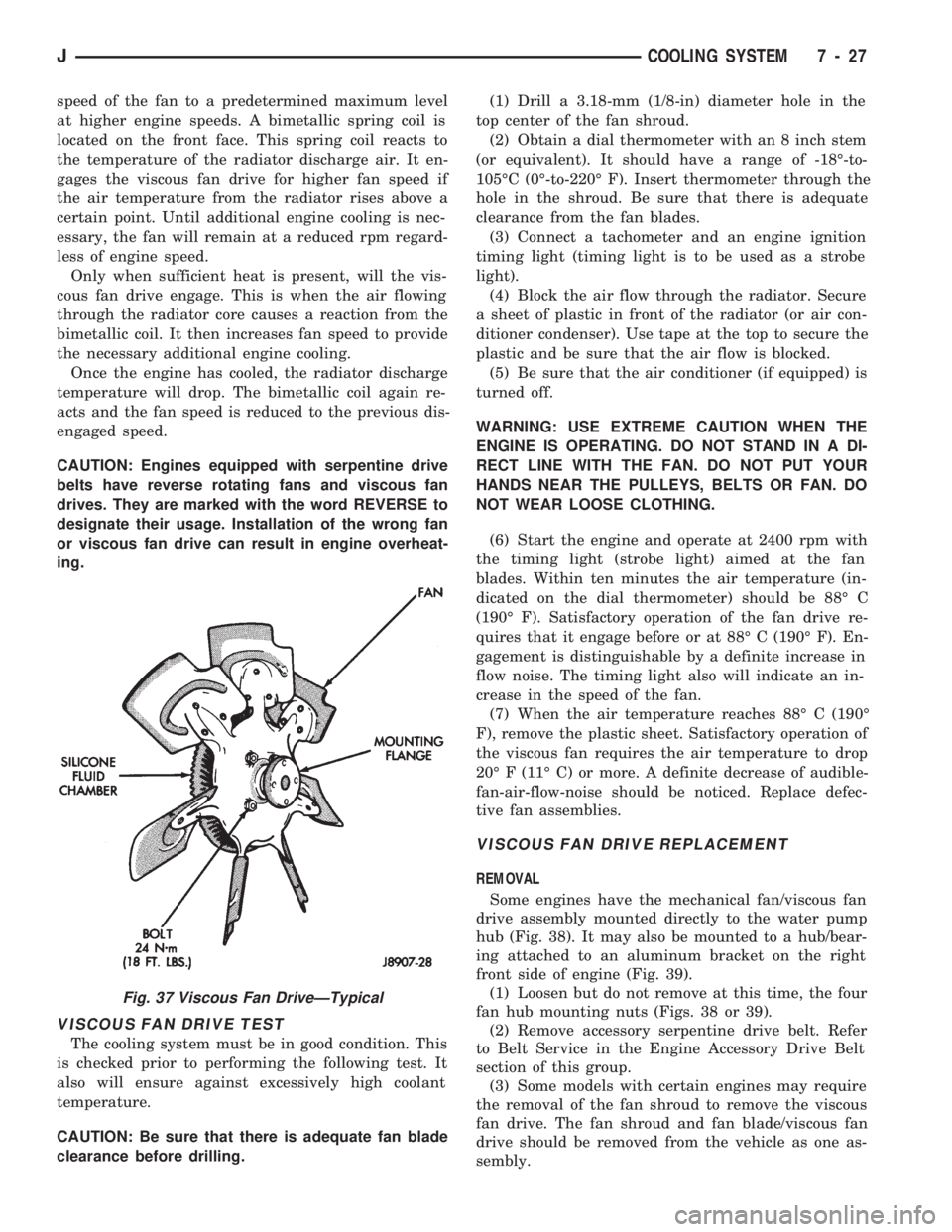
speed of the fan to a predetermined maximum level
at higher engine speeds. A bimetallic spring coil is
located on the front face. This spring coil reacts to
the temperature of the radiator discharge air. It en-
gages the viscous fan drive for higher fan speed if
the air temperature from the radiator rises above a
certain point. Until additional engine cooling is nec-
essary, the fan will remain at a reduced rpm regard-
less of engine speed.
Only when sufficient heat is present, will the vis-
cous fan drive engage. This is when the air flowing
through the radiator core causes a reaction from the
bimetallic coil. It then increases fan speed to provide
the necessary additional engine cooling.
Once the engine has cooled, the radiator discharge
temperature will drop. The bimetallic coil again re-
acts and the fan speed is reduced to the previous dis-
engaged speed.
CAUTION: Engines equipped with serpentine drive
belts have reverse rotating fans and viscous fan
drives. They are marked with the word REVERSE to
designate their usage. Installation of the wrong fan
or viscous fan drive can result in engine overheat-
ing.
VISCOUS FAN DRIVE TEST
The cooling system must be in good condition. This
is checked prior to performing the following test. It
also will ensure against excessively high coolant
temperature.
CAUTION: Be sure that there is adequate fan blade
clearance before drilling.(1) Drill a 3.18-mm (1/8-in) diameter hole in the
top center of the fan shroud.
(2) Obtain a dial thermometer with an 8 inch stem
(or equivalent). It should have a range of -18É-to-
105ÉC (0É-to-220É F). Insert thermometer through the
hole in the shroud. Be sure that there is adequate
clearance from the fan blades.
(3) Connect a tachometer and an engine ignition
timing light (timing light is to be used as a strobe
light).
(4) Block the air flow through the radiator. Secure
a sheet of plastic in front of the radiator (or air con-
ditioner condenser). Use tape at the top to secure the
plastic and be sure that the air flow is blocked.
(5) Be sure that the air conditioner (if equipped) is
turned off.
WARNING: USE EXTREME CAUTION WHEN THE
ENGINE IS OPERATING. DO NOT STAND IN A DI-
RECT LINE WITH THE FAN. DO NOT PUT YOUR
HANDS NEAR THE PULLEYS, BELTS OR FAN. DO
NOT WEAR LOOSE CLOTHING.
(6) Start the engine and operate at 2400 rpm with
the timing light (strobe light) aimed at the fan
blades. Within ten minutes the air temperature (in-
dicated on the dial thermometer) should be 88É C
(190É F). Satisfactory operation of the fan drive re-
quires that it engage before or at 88É C (190É F). En-
gagement is distinguishable by a definite increase in
flow noise. The timing light also will indicate an in-
crease in the speed of the fan.
(7) When the air temperature reaches 88É C (190É
F), remove the plastic sheet. Satisfactory operation of
the viscous fan requires the air temperature to drop
20É F (11É C) or more. A definite decrease of audible-
fan-air-flow-noise should be noticed. Replace defec-
tive fan assemblies.
VISCOUS FAN DRIVE REPLACEMENT
REMOVAL
Some engines have the mechanical fan/viscous fan
drive assembly mounted directly to the water pump
hub (Fig. 38). It may also be mounted to a hub/bear-
ing attached to an aluminum bracket on the right
front side of engine (Fig. 39).
(1) Loosen but do not remove at this time, the four
fan hub mounting nuts (Figs. 38 or 39).
(2) Remove accessory serpentine drive belt. Refer
to Belt Service in the Engine Accessory Drive Belt
section of this group.
(3) Some models with certain engines may require
the removal of the fan shroud to remove the viscous
fan drive. The fan shroud and fan blade/viscous fan
drive should be removed from the vehicle as one as-
sembly.
Fig. 37 Viscous Fan DriveÐTypical
JCOOLING SYSTEM 7 - 27
Page 288 of 1784

OPERATIONAL CHECK WITH VOLTMETER
When the ignition switch is turned to the ON po-
sition, battery potential will register on the voltme-
ter. During engine cranking a lower voltage will
appear on the meter. With the engine running, a
voltage reading higher than the first reading (igni-
tion in ON) should register.
DIAGNOSTIC PROCEDURES
If the indicator operates abnormally, or if an un-
dercharged or overcharged battery condition occurs,
the following procedures may be used to diagnose the
charging system.
Remember that an undercharged battery is often
caused by:
²accessories being left on overnight
²or by a defective switch which allows a bulb, such
as a liftgate or glove box light, to stay on (refer to
Ignition Off Draw Diagnosis).
VISUAL INSPECTION
²Inspect condition of battery cable terminals, bat-
tery posts, connections at engine block, starter motor
solenoid and relay. They should be clean and tight.
Repair as required.
²Inspect all fuses in the fuse block for tightness in
receptacles. They should be properly installed and
tight. Repair or replace as required.²Inspect the electrolyte level in the battery and add
water if necessary.
²Inspect generator mounting bolts for tightness. Re-
place or torque bolt as required. Refer to Torque
Specifications in Battery/Starter/Generator Service.
²Inspect generator drive belt condition and tension.
Tension or replace belt as required. Refer to Belt
Tension Specifications in Battery/Starter/Generator
Service.
²Inspect connection at generator B+ output. It
should be clean and tight. Repair as required.
GENERATOR OUTPUT WIRE RESISTANCE
TEST
Generator output wire resistance test will show
amount of voltage drop across generator output wire
between generator battery terminal and battery pos-
itive post.
PREPARATION
(1) Before starting test make sure vehicle has a
fully charged battery. Test and procedures on how to
check for a fully charged battery are shown in Bat-
tery Test Procedures.
(2) Turn OFF ignition switch.
(3) Disconnect negative cable from battery.
(4) Disconnect generator output wire from genera-
tor output battery terminal.
Fig. 2 Generator Output Wire Resistance Test (Typical)
JBATTERY/STARTING/CHARGING SYSTEMS DIAGNOSTICS 8A - 15
Page 325 of 1784
ENGINE COOLANT TEMPERATURE SENSOR TEST
To perform a complete test of this sensor and its
circuitry, refer to the DRB scan tool. Also refer to the
appropriate Powertrain Diagnostics Procedures man-
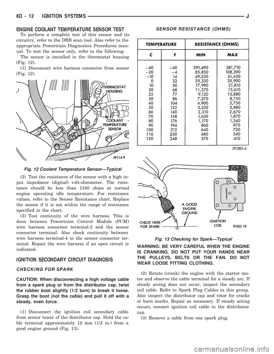
ual. To test the sensor only, refer to the following:
The sensor is installed in the thermostat housing
(Fig. 12).
(1) Disconnect wire harness connector from sensor
(Fig. 12).
(2) Test the resistance of the sensor with a high in-
put impedance (digital) volt-ohmmeter. The resis-
tance should be less than 1340 ohms at normal
engine operating idle temperature. For resistance
values, refer to the Sensor Resistance chart. Replace
the sensor if it is not within the range of resistance
specified in the chart.
(3) Test continuity of the wire harness. This is
done between Powertrain Control Module (PCM)
wire harness connector terminal-2 and the sensor
connector terminal. Also check continuity between
wire harness terminal-4 to the sensor connector ter-
minal. Repair the wire harness if an open circuit is
indicated.
IGNITION SECONDARY CIRCUIT DIAGNOSIS
CHECKING FOR SPARK
CAUTION: When disconnecting a high voltage cable
from a spark plug or from the distributor cap, twist
the rubber boot slightly (1/2 turn) to break it loose.
Grasp the boot (not the cable) and pull it off with a
steady, even force.
(1) Disconnect the ignition coil secondary cable
from center tower of the distributor cap. Hold the ca-
ble terminal approximately 12 mm (1/2 in.) from a
good engine ground (Fig. 13).WARNING: BE VERY CAREFUL WHEN THE ENGINE
IS CRANKING. DO NOT PUT YOUR HANDS NEAR
THE PULLEYS, BELTS OR THE FAN. DO NOT
WEAR LOOSE FITTING CLOTHING.
(2) Rotate (crank) the engine with the starter mo-
tor and observe the cable terminal for a steady arc. If
steady arcing does not occur, inspect the secondary
coil cable. Refer to Spark Plug Cables in this group.
Also inspect the distributor cap and rotor for cracks
or burn marks. Repair as necessary. If steady arcing
occurs, connect ignition coil cable to the distributor
cap.
(3) Remove a cable from one spark plug.
Fig. 12 Coolant Temperature SensorÐTypical
SENSOR RESISTANCE (OHMS)
Fig. 13 Checking for SparkÐTypical
8D - 12 IGNITION SYSTEMSJ
Page 333 of 1784
COMPONENT REMOVAL/INSTALLATION
INDEX
page page
Automatic Shut Down (ASD) Relay........... 20
Camshaft Position Sensor.................. 20
Crankshaft Position Sensor................. 21
Distributor.............................. 23
Engine Coolant Temperature Sensor.......... 22
General Information....................... 20
Ignition Coil............................. 26Intake Manifold Air Temperature Sensor....... 27
Manifold Absolute Pressure (MAP) Sensor..... 27
Oxygen (O2S) Sensor..................... 28
Powertrain Control Module (PCM)............ 28
Spark Plug Secondary Cables............... 29
Spark Plugs............................ 28
Throttle Position Sensor (TPS).............. 29
GENERAL INFORMATION
This section of the group, Component Removal/In-
stallation, will discuss the removal and installation
of ignition system components.
For basic ignition system diagnostics and service
adjustments, refer to the Diagnostics/Service Proce-
dures section of this group.
For system operation and component identification,
refer to the Component Identification/System Opera-
tion section of this group.
AUTOMATIC SHUT DOWN (ASD) RELAY
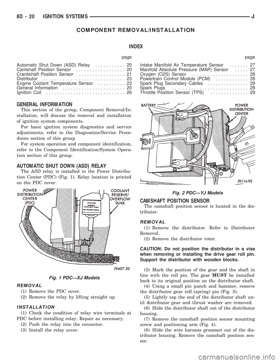
The ASD relay is installed in the Power Distribu-
tion Center (PDC) (Fig. 1). Relay location is printed
on the PDC cover.
REMOVAL
(1) Remove the PDC cover.
(2) Remove the relay by lifting straight up.
INSTALLATION
(1) Check the condition of relay wire terminals at
PDC before installing relay. Repair as necessary.
(2) Push the relay into the connector.
(3) Install the relay cover.
CAMSHAFT POSITION SENSOR
The camshaft position sensor is located in the dis-
tributor.
REMOVAL
(1) Remove the distributor. Refer to Distributor
Removal.
(2) Remove the distributor rotor.
CAUTION: Do not position the distributor in a vise
when removing or installing the drive gear roll pin.
Support the distributor with wooden blocks.
(3) Mark the position of the gear and the shaft in
line with the roll pin. The gearMUSTbe installed
back to its original position on the distributor shaft.
(4) Using a small pin punch and hammer, remove
the distributor gear roll (spring) pin (Fig. 3).
(5) Lightly tap the end of the distributor shaft un-
til distributor gear and thrust washer are removed.
(6) Slide the distributor shaft out of the distributor
housing.
(7) Remove the camshaft position sensor mounting
screw and positioning arm (Fig. 4).
(8) Slide the wire harness grommet out of the dis-
tributor housing. Remove the camshaft position sen-
sor.
Fig. 1 PDCÐXJ Models
Fig. 2 PDCÐYJ Models
8D - 20 IGNITION SYSTEMSJ
Page 342 of 1784
cleaning, file the center electrode flat with a small
point file or jewelers file before adjusting gap.
PLUG GAP ADJUSTMENT
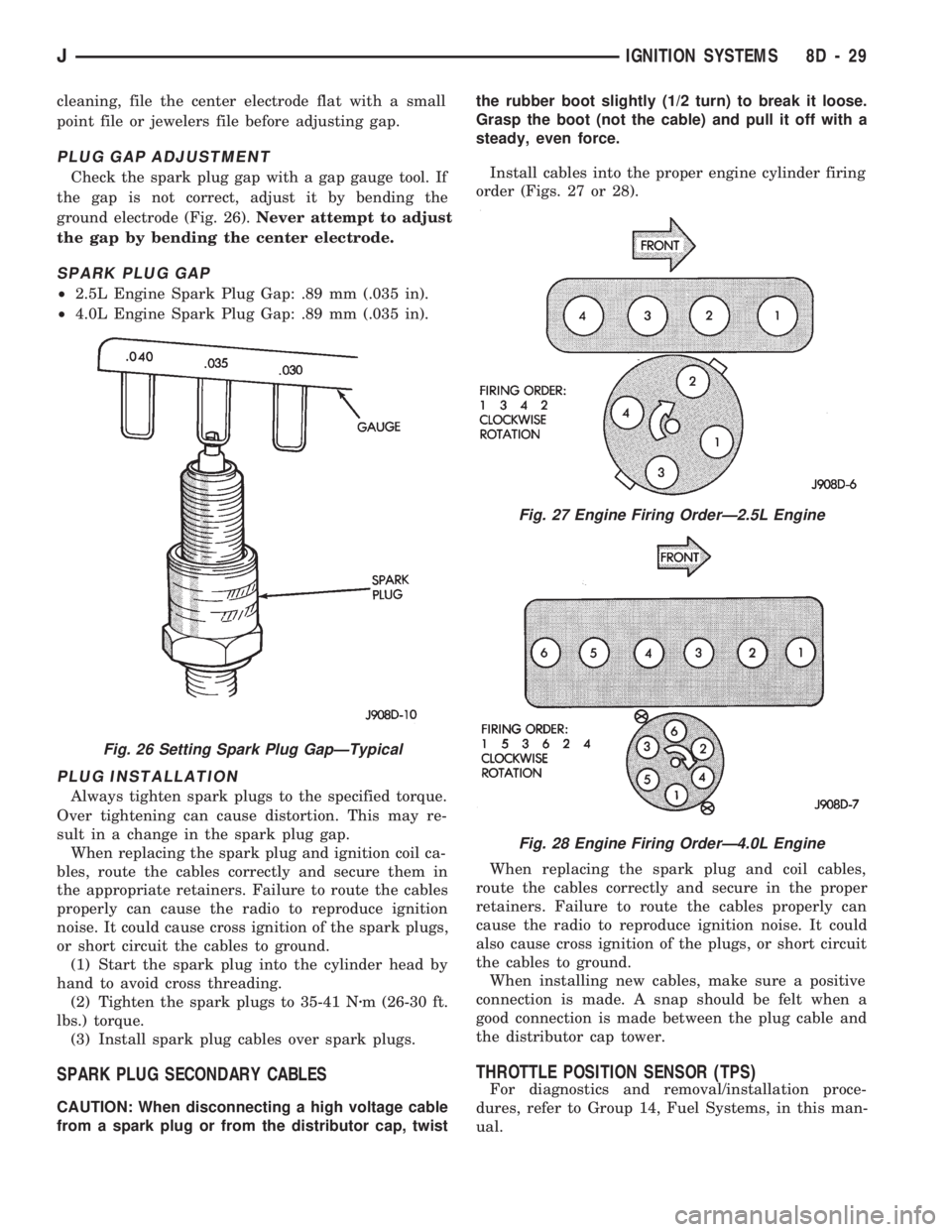
Check the spark plug gap with a gap gauge tool. If
the gap is not correct, adjust it by bending the
ground electrode (Fig. 26).Never attempt to adjust
the gap by bending the center electrode.
SPARK PLUG GAP
²2.5L Engine Spark Plug Gap: .89 mm (.035 in).
²4.0L Engine Spark Plug Gap: .89 mm (.035 in).
PLUG INSTALLATION
Always tighten spark plugs to the specified torque.
Over tightening can cause distortion. This may re-
sult in a change in the spark plug gap.
When replacing the spark plug and ignition coil ca-
bles, route the cables correctly and secure them in
the appropriate retainers. Failure to route the cables
properly can cause the radio to reproduce ignition
noise. It could cause cross ignition of the spark plugs,
or short circuit the cables to ground.
(1) Start the spark plug into the cylinder head by
hand to avoid cross threading.
(2) Tighten the spark plugs to 35-41 Nzm (26-30 ft.
lbs.) torque.
(3) Install spark plug cables over spark plugs.
SPARK PLUG SECONDARY CABLES
CAUTION: When disconnecting a high voltage cable
from a spark plug or from the distributor cap, twistthe rubber boot slightly (1/2 turn) to break it loose.
Grasp the boot (not the cable) and pull it off with a
steady, even force.
Install cables into the proper engine cylinder firing
order (Figs. 27 or 28).
When replacing the spark plug and coil cables,
route the cables correctly and secure in the proper
retainers. Failure to route the cables properly can
cause the radio to reproduce ignition noise. It could
also cause cross ignition of the plugs, or short circuit
the cables to ground.
When installing new cables, make sure a positive
connection is made. A snap should be felt when a
good connection is made between the plug cable and
the distributor cap tower.
THROTTLE POSITION SENSOR (TPS)
For diagnostics and removal/installation proce-
dures, refer to Group 14, Fuel Systems, in this man-
ual.
Fig. 26 Setting Spark Plug GapÐTypical
Fig. 27 Engine Firing OrderÐ2.5L Engine
Fig. 28 Engine Firing OrderÐ4.0L Engine
JIGNITION SYSTEMS 8D - 29
Page 348 of 1784

INSTRUMENT PANEL AND GAUGES
GROUP INDEX
page page
INSTRUMENT PANEL AND GAUGESÐXJ..... 1INSTRUMENT PANEL AND GAUGESÐYJ.... 14
INSTRUMENT PANEL AND GAUGESÐXJE
CONTENTS
page page
INSTRUMENT CLUSTER DIAGNOSIS........ 3
INSTRUMENT CLUSTER GENERAL INFORMATION.. 1
INSTRUMENT CLUSTER SERVICE PROCEDURES... 5
SPECIFICATIONS....................... 13
INSTRUMENT CLUSTER GENERAL INFORMATION
INDEX
page page
4WD Indicator Lamp........................ 2
Anti-Lock Brake Indicator Lamp............... 2
Brake Indicator Lamp....................... 2
Coolant Temperature Gauge................. 1
Coolant Temperature Indicator Lamp........... 1
Fuel Gauge.............................. 2
Low Fuel Warning Lamp..................... 2Malfunction Indicator Lamp (Check Engine)...... 2
Oil Pressure Gauge....................... 1
Oil Pressure Indicator Lamp.................. 1
Speedometer/Odometer System.............. 2
Tachometer.............................. 2
Upshift Indicator Lamp...................... 2
Voltmeter............................... 1
With the ignition switch in the ON or START posi-
tion, voltage supplied to the instrument cluster is lim-
ited by fuse #17. The voltage is supplied to all the
gauges and indicator lamps through the instrument
cluster printed circuit.
With the ignition switch in the OFF position, volt-
age is not supplied to the instrument cluster and the
gauges do not indicate any vehicle condition.
VOLTMETER
The voltmeter measures battery or generator out-
put voltage, whichever is greater.
OIL PRESSURE GAUGE
The oil pressure gauge pointer position is controlled
by a magnetic field created by electrical current flow
through the coils within the gauge. A change in current
flow will change the magnetic field which changes the
pointer position. The oil pressure sender is a variable
resistor that changes electrical resistance with a change
in oil pressure (values shown in Specifications chart).
OIL PRESSURE INDICATOR LAMP
Voltage is supplied to one side of the indicator bulb
and the oil pressure switch is connected to the other
side. When oil pressure is too low the switch closes
providing a path to ground, and the indicator bulb
lights.
COOLANT TEMPERATURE GAUGE
The coolant temperature gauge pointer position is
controlled by a magnetic field created by electrical
current flow through the coils within the gauge. A
change in current flow will change the magnetic field
which changes the pointer position. The coolant tem-
perature sensor is a thermistor that changes electri-
cal resistance with a change in coolant temperature
(values shown in Specifications chart).
COOLANT TEMPERATURE INDICATOR LAMP
Voltage is supplied to one side of the indicator bulb
and the coolant temperature switch is connected to the
JINSTRUMENT PANEL AND GAUGES 8E - 1
Page 349 of 1784
other side. When coolant temperature is too high the
switch closes providing a path to ground, and the indi-
cator bulb lights.
TACHOMETER
The tachometer displays the engine speed (RPM).
With the engine running, the tachometer receives an
engine speed signal from the Powertrain Control
Module pin 43 (values shown in Specifications chart).
SPEEDOMETER/ODOMETER SYSTEM
The speedometer/odometer system consists of an elec-
tric speedometer and pushbutton reset odometer
mounted in the cluster. The system also includes the
wire harness from the cluster to the vehicle speed sen-
sor at the transmission, and the adapter and pinion in
the transmission. A signal is sent from a transmission
mounted vehicle speed sensor to the speedometer/odom-
eter circuitry through the wiring harness. Refer to
Group 21 - Transmission for selecting the proper pinion,
and selecting and indexing the proper adapter.
FUEL GAUGE
The fuel gauge pointer position is controlled by a
magnetic field created by electrical current flow through
the coils within the gauge. A change in current flow will
change the magnetic field which changes the pointer po-
sition. The fuel level sender is a variable resistor that
changes electrical resistance with a change of the level
of fuel in the tank (values shown in Specifications
chart).
LOW FUEL WARNING LAMP
The low fuel warning lamp will light when the fuel
level falls below approximately 4 gallons. A low fuel
warning module controls when the lamp will light.
When the module senses 66.5 ohms or less from the
fuel level sender for 10 continuous seconds, the lamp
will light. The lamp will remain on until the module
senses 63.5 ohms or more from the fuel level sender
for 20 continuous seconds.
UPSHIFT INDICATOR LAMP
Vehicles equipped with manual transmissions have an
optional upshift indicator lamp. The lamp is controlled
by the Powertrain Control Module. The lamp lights to
indicate when the driver should shift to the next high-
est gear for best fuel economy. The Powertrain Control
Module will turn the lamp off after 3 to 5 seconds if the
upshift is not performed. The lamp will remain off until
the vehicle stops accelerating and is brought back to the
range of lamp operation or shifted into another gear.
The indicator lamp is normally illuminated when
the ignition switch is turned ON and is turned off
when the engine is started. The lamp will be lighted
during engine operation according to engine speed
and load.
BRAKE INDICATOR LAMP
The brake indicator lamp warns the driver that the
parking brake is applied or that hydraulic pressure in
the split brake system is unequal.
Voltage is supplied through the brake indicator
bulb to 3 switches. A path to ground for the current
is available if:
²The brake warning switch is closed (with unequal
brake system hydraulic pressures), or
²
The ignition switch is in the START position (to test
the bulb), or
²The park brake switch is closed (with the parking
brake applied).
ANTI-LOCK BRAKE SYSTEM (ABS) INDICATOR
LAMP
The anti-lock brake system (ABS) lamp lights to in-
dicate a system self-check is in process at vehicle
start-up. If light remains on after start-up or comes
on and stays on while driving, it may indicate that
the ABS system has detected a malfunction or has
become inoperative.
4WD INDICATOR LAMP
COMMAND-TRAC 4WD
The PART TIME lamp lights when the vehicle is en-
gaged in four-wheel drive mode. Voltage is supplied to
one side of the indicator bulb. A switch in the transfer
case area is connected to the other side of the indicator
bulb. When the switch is closed, a path to ground is pro-
vided and the indicator bulb lights.
SELECT-TRAC 4WD
The four-wheel drive icon or FULL TIME lamp
lights when the vehicle is engaged in full time four-
wheel drive mode. The PART TIME lamp lights when
the vehicle is in part time four-wheel drive mode.
Voltage is supplied to one side of the indicators.
Switches in the transfer case area are connected to
the other side of the indicator bulbs. When a switch
is closed, a path to ground is provided and the indi-
cator bulb lights.
MALFUNCTION INDICATOR LAMP (CHECK ENGINE)
The Malfunction Indicator Lamp (Check Engine)
lights each time the ignition switch is turned ON and
stays on for 3 seconds as a bulb test.
If the PCM receives an incorrect signal or no signal
from certain sensors or emission related systems the
lamp is turned on (pin 32 of PCM). This is a warning
that the PCM has recorded a system or sensor mal-
function. In some cases when a diagnostic trouble
code is declared the PCM will go into a limp-in mode
in an attempt to keep the system operating. It sig-
nals an immediate need for service.
The lamp also can be used to display diagnostic
trouble codes (DTC). Cycle the ignition switch ON,
OFF, ON, OFF, ON within 5 seconds. This will allow
any trouble codes stored in the PCM memory to be
displayed in a series of flashes representing digits.
8E - 2 XJ INSTRUMENT PANEL AND GAUGESJ