1994 JEEP CHEROKEE ECU
[x] Cancel search: ECUPage 170 of 1784
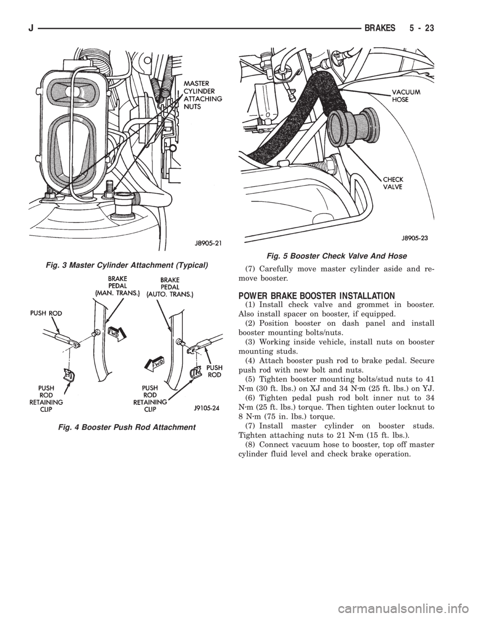
(7) Carefully move master cylinder aside and re-
move booster.
POWER BRAKE BOOSTER INSTALLATION
(1) Install check valve and grommet in booster.
Also install spacer on booster, if equipped.
(2) Position booster on dash panel and install
booster mounting bolts/nuts.
(3) Working inside vehicle, install nuts on booster
mounting studs.
(4) Attach booster push rod to brake pedal. Secure
push rod with new bolt and nuts.
(5) Tighten booster mounting bolts/stud nuts to 41
Nzm (30 ft. lbs.) on XJ and 34 Nzm (25 ft. lbs.) on YJ.
(6) Tighten pedal push rod bolt inner nut to 34
Nzm (25 ft. lbs.) torque. Then tighten outer locknut to
8Nzm (75 in. lbs.) torque.
(7) Install master cylinder on booster studs.
Tighten attaching nuts to 21 Nzm (15 ft. lbs.).
(8) Connect vacuum hose to booster, top off master
cylinder fluid level and check brake operation.
Fig. 3 Master Cylinder Attachment (Typical)
Fig. 4 Booster Push Rod Attachment
Fig. 5 Booster Check Valve And Hose
JBRAKES 5 - 23
Page 173 of 1784
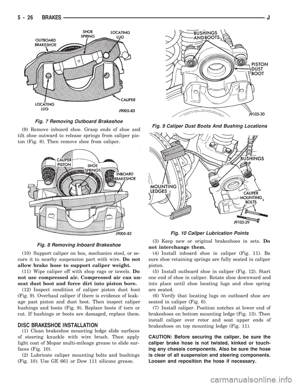
(9) Remove inboard shoe. Grasp ends of shoe and
tilt shoe outward to release springs from caliper pis-
ton (Fig. 8). Then remove shoe from caliper.
(10) Support caliper on box, mechanics stool, or se-
cure it to nearby suspension part with wire.Do not
allow brake hose to support caliper weight.
(11) Wipe caliper off with shop rags or towels.Do
not use compressed air. Compressed air can un-
seat dust boot and force dirt into piston bore.
(12) Inspect condition of caliper piston dust boot
(Fig. 9). Overhaul caliper if there is evidence of leak-
age past piston and dust boot. Then inspect caliper
bushings and boots (Fig. 9). Replace boots if torn or
cut. If bushings or boots are damaged, replace them.
DISC BRAKESHOE INSTALLATION
(1) Clean brakeshoe mounting ledge slide surfaces
of steering knuckle with wire brush. Then apply
light coat of Mopar multi-mileage grease to slide sur-
faces (Fig. 10).
(2) Lubricate caliper mounting bolts and bushings
(Fig. 10). Use GE 661 or Dow 111 silicone grease.(3) Keep new or original brakeshoes in sets.Do
not interchange them.
(4) Install inboard shoe in caliper (Fig. 11). Be
sure shoe retaining springs are fully seated in caliper
piston.
(5) Install outboard shoe in caliper (Fig. 12). Start
one end of shoe in caliper. Rotate shoe downward and
into place until shoe locating lugs and shoe spring
are seated.
(6) Verify that locating lugs on outboard shoe are
seated in caliper (Fig. 6).
(7) Install caliper. Position notches at lower end of
brakeshoes on bottom mounting ledge (Fig. 13). Then
install caliper over rotor and seat upper ends of
brakeshoes on top mounting ledge (Fig. 11).
CAUTION: Before securing the caliper, be sure the
caliper brake hose is not twisted, kinked or touch-
ing any chassis components. Also be sure the hose
is clear of all suspension and steering components.
Loosen and reposition the hose if necessary.
Fig. 7 Removing Outboard Brakeshoe
Fig. 8 Removing Inboard Brakeshoe
Fig. 9 Caliper Dust Boots And Bushing Locations
Fig. 10 Caliper Lubrication Points
5 - 26 BRAKESJ
Page 177 of 1784
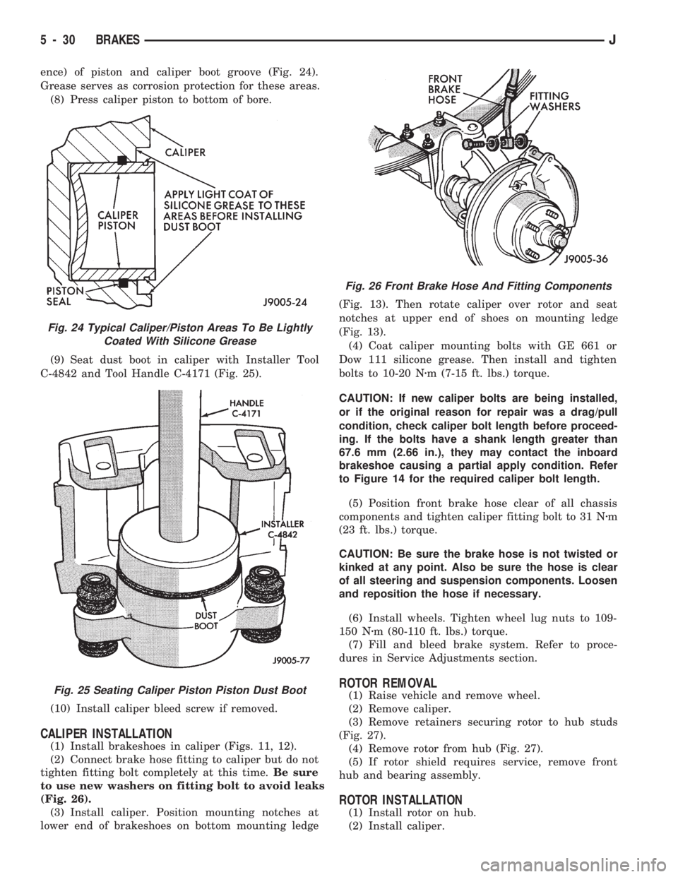
ence) of piston and caliper boot groove (Fig. 24).
Grease serves as corrosion protection for these areas.
(8) Press caliper piston to bottom of bore.
(9) Seat dust boot in caliper with Installer Tool
C-4842 and Tool Handle C-4171 (Fig. 25).
(10) Install caliper bleed screw if removed.
CALIPER INSTALLATION
(1) Install brakeshoes in caliper (Figs. 11, 12).
(2) Connect brake hose fitting to caliper but do not
tighten fitting bolt completely at this time.Be sure
to use new washers on fitting bolt to avoid leaks
(Fig. 26).
(3) Install caliper. Position mounting notches at
lower end of brakeshoes on bottom mounting ledge(Fig. 13). Then rotate caliper over rotor and seat
notches at upper end of shoes on mounting ledge
(Fig. 13).
(4) Coat caliper mounting bolts with GE 661 or
Dow 111 silicone grease. Then install and tighten
bolts to 10-20 Nzm (7-15 ft. lbs.) torque.
CAUTION: If new caliper bolts are being installed,
or if the original reason for repair was a drag/pull
condition, check caliper bolt length before proceed-
ing. If the bolts have a shank length greater than
67.6 mm (2.66 in.), they may contact the inboard
brakeshoe causing a partial apply condition. Refer
to Figure 14 for the required caliper bolt length.
(5) Position front brake hose clear of all chassis
components and tighten caliper fitting bolt to 31 Nzm
(23 ft. lbs.) torque.
CAUTION: Be sure the brake hose is not twisted or
kinked at any point. Also be sure the hose is clear
of all steering and suspension components. Loosen
and reposition the hose if necessary.
(6) Install wheels. Tighten wheel lug nuts to 109-
150 Nzm (80-110 ft. lbs.) torque.
(7) Fill and bleed brake system. Refer to proce-
dures in Service Adjustments section.
ROTOR REMOVAL
(1) Raise vehicle and remove wheel.
(2) Remove caliper.
(3) Remove retainers securing rotor to hub studs
(Fig. 27).
(4) Remove rotor from hub (Fig. 27).
(5) If rotor shield requires service, remove front
hub and bearing assembly.
ROTOR INSTALLATION
(1) Install rotor on hub.
(2) Install caliper.
Fig. 24 Typical Caliper/Piston Areas To Be Lightly
Coated With Silicone Grease
Fig. 25 Seating Caliper Piston Piston Dust Boot
Fig. 26 Front Brake Hose And Fitting Components
5 - 30 BRAKESJ
Page 178 of 1784
(3) Install new spring nuts on wheel studs.
(4) Install wheel and lower vehicle.
DISC BRAKE ROTOR THICKNESS
Rotor minimum usable thickness is 22.7 mm (0.89
in.). This dimension is either cast, or stamped on the
rotor hub, or outer edge.
Measure rotor thickness at the center of the brake-
shoe contact surface.
Replace the rotor if worn below minimum thick-
ness. Also replace the rotor if refinishing would re-
duce thickness below the allowable minimum.
DISC BRAKE ROTOR RUNOUT
Check rotor lateral runout whenever pedal pulsa-
tion, or rapid, uneven brakelining wear has occurred.
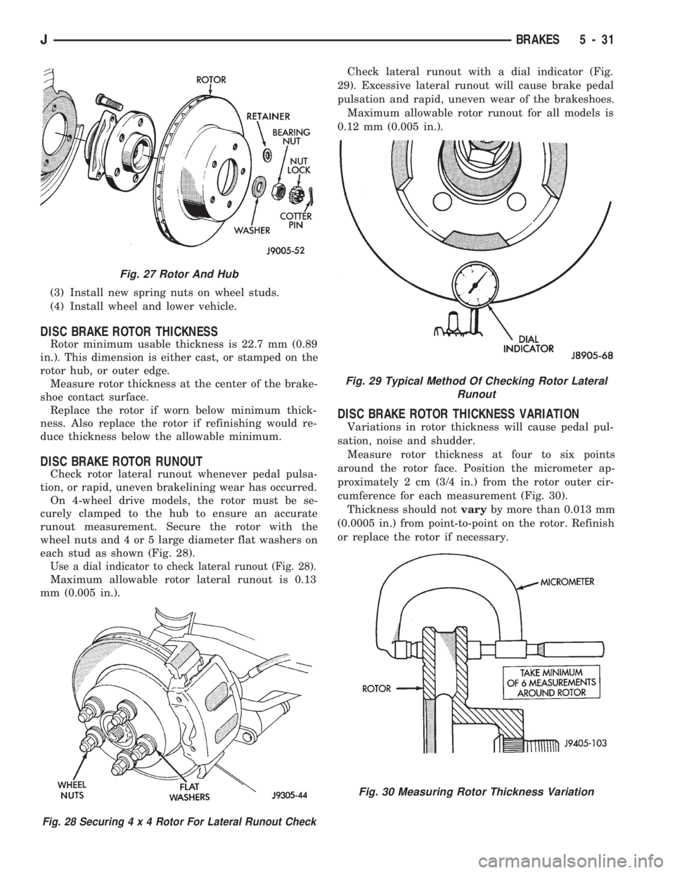
On 4-wheel drive models, the rotor must be se-
curely clamped to the hub to ensure an accurate
runout measurement. Secure the rotor with the
wheel nuts and 4 or 5 large diameter flat washers on
each stud as shown (Fig. 28).
Use a dial indicator to check lateral runout (Fig. 28).
Maximum allowable rotor lateral runout is 0.13
mm (0.005 in.).Check lateral runout with a dial indicator (Fig.
29). Excessive lateral runout will cause brake pedal
pulsation and rapid, uneven wear of the brakeshoes.
Maximum allowable rotor runout for all models is
0.12 mm (0.005 in.).
DISC BRAKE ROTOR THICKNESS VARIATION
Variations in rotor thickness will cause pedal pul-
sation, noise and shudder.
Measure rotor thickness at four to six points
around the rotor face. Position the micrometer ap-
proximately 2 cm (3/4 in.) from the rotor outer cir-
cumference for each measurement (Fig. 30).
Thickness should notvaryby more than 0.013 mm
(0.0005 in.) from point-to-point on the rotor. Refinish
or replace the rotor if necessary.
Fig. 27 Rotor And Hub
Fig. 28 Securing4x4Rotor For Lateral Runout Check
Fig. 29 Typical Method Of Checking Rotor Lateral
Runout
Fig. 30 Measuring Rotor Thickness Variation
JBRAKES 5 - 31
Page 181 of 1784
DRUM BRAKES
INDEX
page page
Brake Drum Refinishing.................... 37
Drum Brake Adjustment................... 35
Drum Brakeshoe Installation................ 34
Drum Brakeshoe Removal (Figs. 1 and 2)...... 34
Support Plate Replacement................. 37Wheel Cylinder Installation................. 37
Wheel Cylinder Overhaul (Figs. 8 and 9)....... 36
Wheel Cylinder Removal................... 36
Wheel Nut Tightening..................... 37
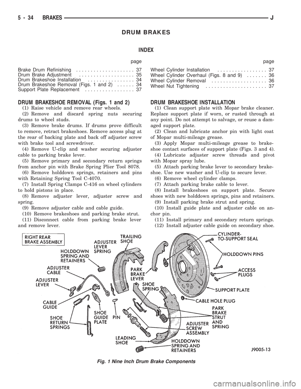
DRUM BRAKESHOE REMOVAL (Figs. 1 and 2)
(1) Raise vehicle and remove rear wheels.
(2) Remove and discard spring nuts securing
drums to wheel studs.
(3) Remove brake drums. If drums prove difficult
to remove, retract brakeshoes. Remove access plug at
the rear of backing plate and back off adjuster screw
with brake tool and screwdriver.
(4) Remove U-clip and washer securing adjuster
cable to parking brake lever.
(5) Remove primary and secondary return springs
from anchor pin with Brake Spring Plier Tool 8078.
(6) Remove holddown springs, retainers and pins
with Retaining Spring Tool C-4070.
(7) Install Spring Clamps C-416 on wheel cylinders
to hold pistons in place.
(8) Remove adjuster lever, adjuster screw and
spring.
(9) Remove adjuster cable and cable guide.
(10) Remove brakeshoes and parking brake strut.
(11) Disconnect cable from parking brake lever
and remove lever.
DRUM BRAKESHOE INSTALLATION
(1) Clean support plate with Mopar brake cleaner.
Replace support plate if worn, or rusted through at
any point. Do not attempt to salvage, or reuse a dam-
aged support plate.
(2) Clean and lubricate anchor pin with light coat
of Mopar multi-mileage grease.
(3) Apply Mopar multi-mileage grease to brake-
shoe contact surfaces of support plate (Figs. 3 and 4).
(4) Lubricate adjuster screw threads and pivot
with Mopar spray lube.
(5) Attach parking brake lever to secondary brake-
shoe. Use new washer and U-clip to secure lever.
(6) Remove wheel cylinder clamps.
(7) Attach parking brake cable to lever.
(8) Install brakeshoes on support plate. Secure
shoes with new holddown springs, pins and retainers.
(9) Install parking brake strut and spring.
(10) Install guide plate and adjuster cable on an-
chor pin.
(11) Install primary and secondary return springs.
(12) Install adjuster cable guide on secondary shoe.
Fig. 1 Nine Inch Drum Brake Components
5 - 34 BRAKESJ
Page 186 of 1784
ABS SYSTEM OPERATION
INDEX
page page
Acceleration Switch....................... 41
Combination Valve....................... 42
Electronic Control Unit (ECU)............... 41
General Information....................... 39
Hydraulic Control Unit (HCU)................ 39
Ignition Switch........................... 42Master Cylinder.......................... 40
Pedal Travel Sensor...................... 41
Power Brake Booster..................... 40
System Relays.......................... 42
System Warning Lights.................... 42
Wheel Speed Sensors..................... 41
GENERAL INFORMATION
The Jeep antilock brake system (ABS) is an elec-
tronically operated, all-wheel brake control system.
Major components include the master cylinder, vac-
uum power brake booster, ECU, hydraulic control
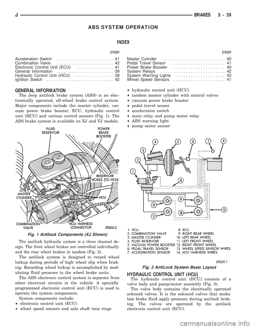
unit (HCU) and various control sensors (Fig. 1). The
ABS brake system is available on XJ and YJ models.
The antilock hydraulic system is a three channel de-
sign. The front wheel brakes are controlled individually
and the rear wheel brakes in tandem (Fig. 2).
The antilock system is designed to retard wheel
lockup during periods of high wheel slip when brak-
ing. Retarding wheel lockup is accomplished by mod-
ulating fluid pressure to the wheel brake units.
The ABS electronic control system is separate from
other electrical circuits in the vehicle. A specially
programmed electronic control unit (ECU) is used to
operate the system components.
System components include:
²electronic control unit (ECU)
²wheel speed sensors and axle shaft tone rings²hydraulic control unit (HCU)
²tandem master cylinder with central valves
²vacuum power brake booster
²pedal travel sensor
²acceleration switch
²main relay and pump motor relay
²ABS warning light
²pump motor sensor
HYDRAULIC CONTROL UNIT (HCU)
The hydraulic control unit (HCU) consists of a
valve body and pump/motor assembly (Fig. 3).
The valve body contains the electrically operated
solenoid valves. It is the solenoid valves that modu-
late brake fluid apply pressure during antilock brak-
ing. The valves are operated by the antilock
electronic control unit (ECU).
Fig. 1 Antilock Components (XJ Shown)
Fig. 2 AntiLock System Basic Layout
JBRAKES 5 - 39
Page 187 of 1784
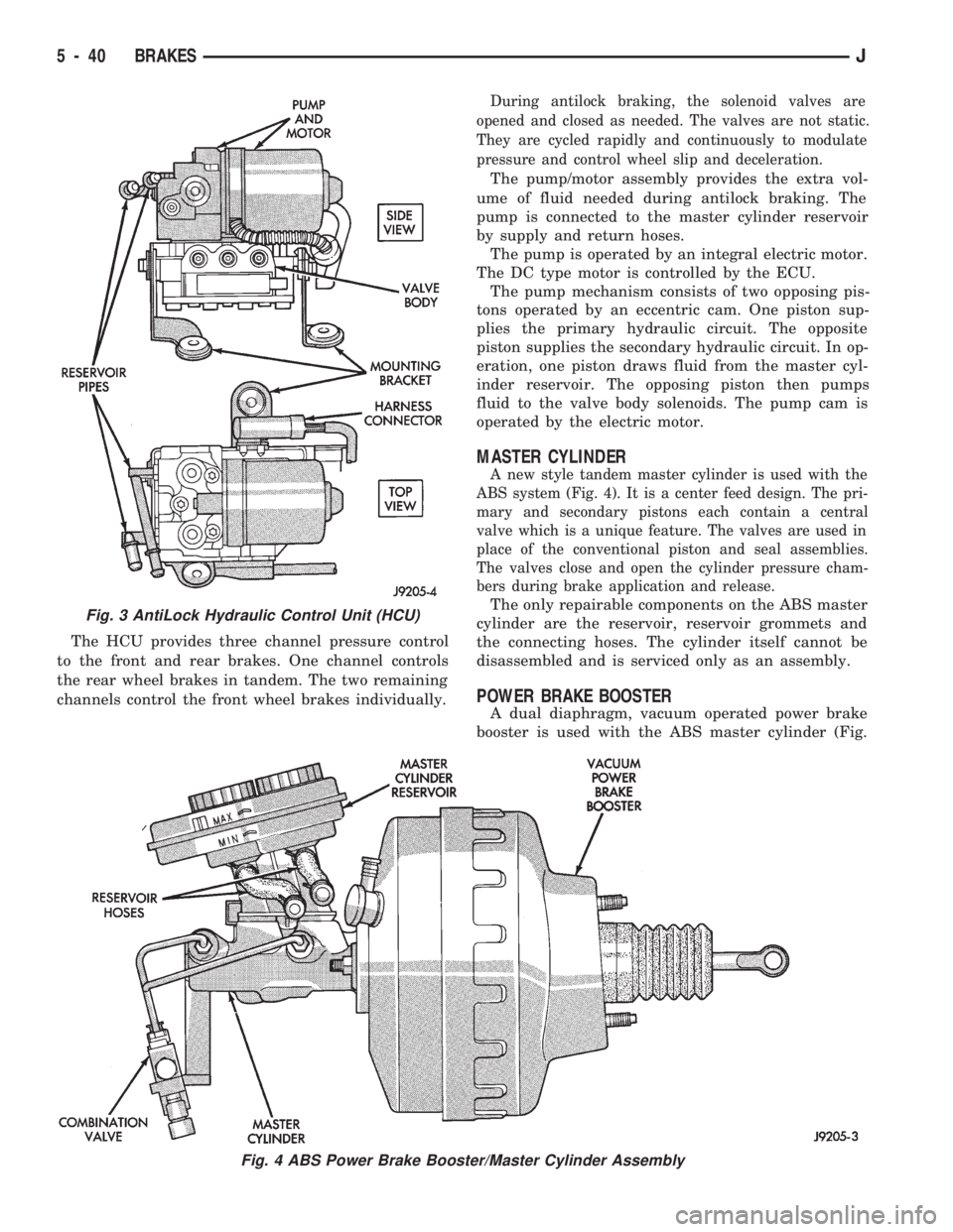
The HCU provides three channel pressure control
to the front and rear brakes. One channel controls
the rear wheel brakes in tandem. The two remaining
channels control the front wheel brakes individually.
During antilock braking, the solenoid valves are
opened and closed as needed. The valves are not static.
They are cycled rapidly and continuously to modulate
pressure and control wheel slip and deceleration.
The pump/motor assembly provides the extra vol-
ume of fluid needed during antilock braking. The
pump is connected to the master cylinder reservoir
by supply and return hoses.
The pump is operated by an integral electric motor.
The DC type motor is controlled by the ECU.
The pump mechanism consists of two opposing pis-
tons operated by an eccentric cam. One piston sup-
plies the primary hydraulic circuit. The opposite
piston supplies the secondary hydraulic circuit. In op-
eration, one piston draws fluid from the master cyl-
inder reservoir. The opposing piston then pumps
fluid to the valve body solenoids. The pump cam is
operated by the electric motor.
MASTER CYLINDER
A new style tandem master cylinder is used with the
ABS system (Fig. 4). It is a center feed design. The pri-
mary and secondary pistons each contain a central
valve which is a unique feature. The valves are used in
place of the conventional piston and seal assemblies.
The valves close and open the cylinder pressure cham-
bers during brake application and release.
The only repairable components on the ABS master
cylinder are the reservoir, reservoir grommets and
the connecting hoses. The cylinder itself cannot be
disassembled and is serviced only as an assembly.
POWER BRAKE BOOSTER
A dual diaphragm, vacuum operated power brake
booster is used with the ABS master cylinder (Fig.
Fig. 3 AntiLock Hydraulic Control Unit (HCU)
Fig. 4 ABS Power Brake Booster/Master Cylinder Assembly
5 - 40 BRAKESJ
Page 188 of 1784
4). The engine intake manifold serves as the vacuum
source for booster operation.
The booster is mounted on the engine compartment
side of the dash panel. The master cylinder is
mounted on attaching studs at the front of the
booster. The master cylinder central valves are di-
rectly actuated by the booster push rod.
The pedal travel sensor is mounted in the forward
face of the booster shell. The sensor plunger is actu-
ated by the booster diaphragm plate.
PEDAL TRAVEL SENSOR
The pedal travel sensor signals brake pedal posi-
tion to the antilock ECU. The sensor signal is based
on changes in electrical resistance. The resistance
changes occur in steps that are generated by changes
in brake pedal position. A resistance signal gener-
ated by changing brake pedal position, will cause the
ECU to run the antilock pump when necessary.
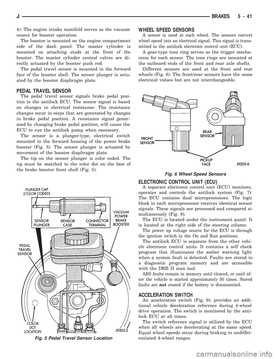
The sensor is a plunger-type, electrical switch
mounted in the forward housing of the power brake
booster (Fig. 5). The sensor plunger is actuated by
movement of the booster diaphragm plate.
The tip on the sensor plunger is color coded. The
tip must be matched to the color dot on the face of
the brake booster front shell (Fig. 5).
WHEEL SPEED SENSORS
A sensor is used at each wheel. The sensors convert
wheel speed into an electrical signal. This signal is trans-
mitted to the antilock electronic control unit (ECU).
A gear-type tone ring serves as the trigger mecha-
nism for each sensor. The tone rings are mounted at
the outboard ends of the front and rear axle shafts.
Different sensors are used at the front and rear
wheels (Fig. 6). The front/rear sensors have the same
electrical values but are not interchangeable.
ELECTRONIC CONTROL UNIT (ECU)
A separate electronic control unit (ECU) monitors,
operates and controls the antilock system (Fig. 7).
The ECU contains dual microprocessors. The logic
block in each microprocessor receives identical sensor
signals. These signals are processed and compared si-
multaneously (Fig. 8).
The ECU is located under the instrument panel. It
is located at the right side of the steering column.
The power up voltage source for the ECU is through
the ignition switch in the On and Run positions.
The antilock ECU is separate from the other vehi-
cle electronic control units. It contains a self check
program that illuminates the amber warning light
when a system fault is detected. Faults are stored in
a diagnostic program memory and are accessible
with the DRB II scan tool.
ABS faults remain in memory until cleared, or until af-
ter the vehicle is started approximately 50 times. Stored
faults arenoterased if the battery is disconnected.
ACCELERATION SWITCH
An acceleration switch (Fig. 9), provides an addi-
tional vehicle deceleration reference during 4-wheel
drive operation. The switch is monitored by the anti-
lock ECU at all times.
The switch reference signal is utilized by the ECU
when all wheels are decelerating at the same speed.
Equal wheel speeds occur during braking in undiffer-
entiated 4-wheel ranges.
Fig. 5 Pedal Travel Sensor Location
Fig. 6 Wheel Speed Sensors
JBRAKES 5 - 41