1994 JEEP CHEROKEE front
[x] Cancel search: frontPage 944 of 1784
XJ BUMPERS
INDEX
page page
Front Bumper............................ 3
Front Tow Hooks......................... 5Rear Bumper............................ 6
FRONT BUMPER
REMOVAL/DISASSEMBLY
(1) The bumper guards, end caps and tow hooks
can be removed from XJ front bumpers with the
bumper attached to the vehicle. Do not remove the
bumper from the vehicle if only these components re-
quire service.
If equipped with a brush guard, refer to the
Brush Guard Removal within Group 23ÐBody
Components.
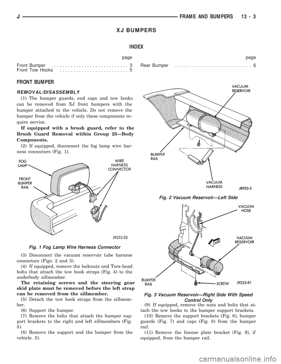
(2) If equipped, disconnect the fog lamp wire har-
ness connectors (Fig. 1).
(3) Disconnect the vacuum reservoir tube harness
connectors (Figs. 2 and 3).
(4) If equipped, remove the locknuts and Torx-head
bolts that attach the tow hook straps (Fig. 4) to the
underbody sillmember.
The retaining screws and the steering gear
skid plate must be removed before the left strap
can be removed from the sillmember.
(5) Detach the tow hook straps from the sillmem-
ber.
(6) Support the bumper.
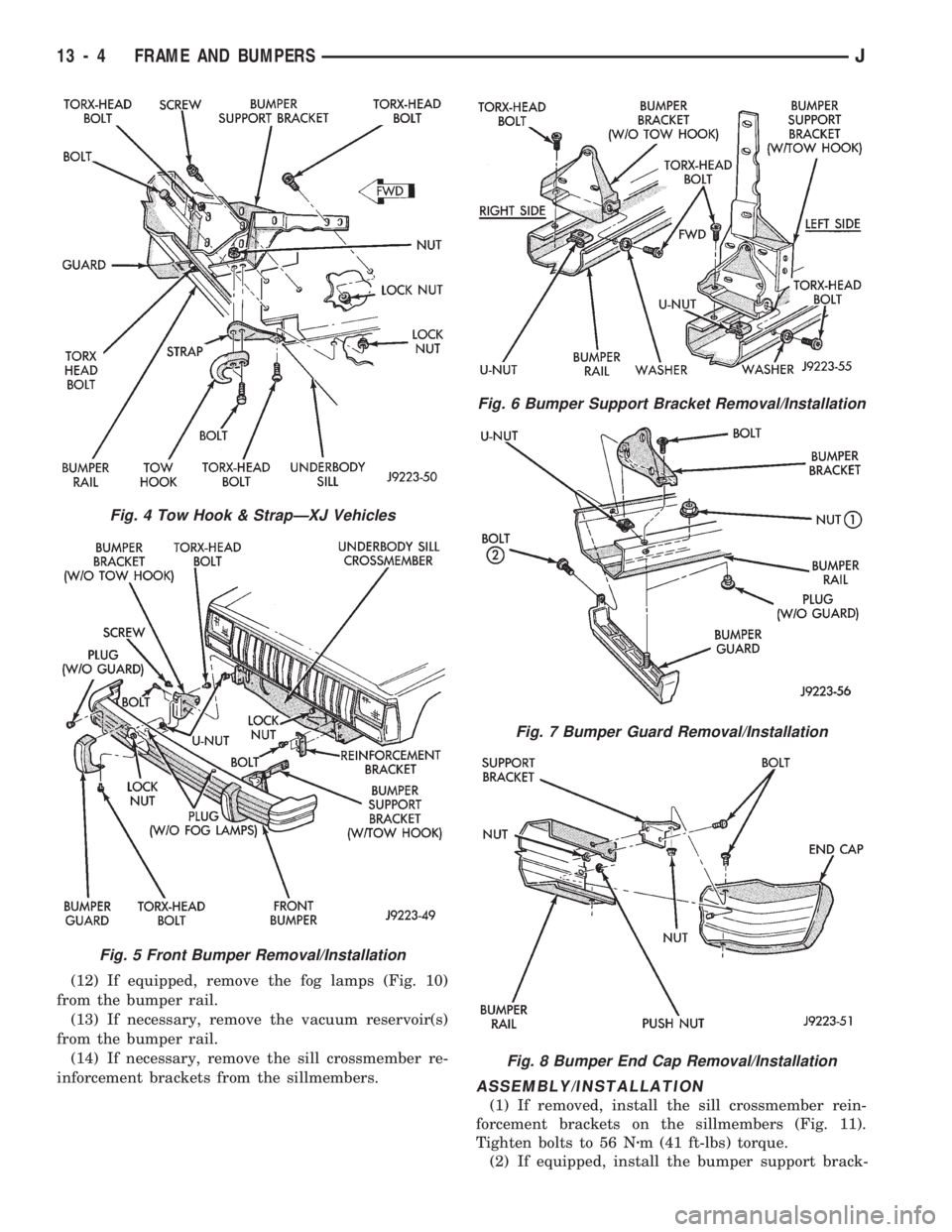
(7) Remove the bolts that attach the bumper sup-
port brackets to the right and left sillmembers (Fig.
5).
(8) Remove the support and the bumper from the
vehicle. 5).(9) If equipped, remove the nuts and bolts that at-
tach the tow hooks to the bumper support brackets.
(10) Remove the support brackets (Fig. 6), bumper
guards (Fig. 7) and caps (Fig. 8) from the bumper
rail.
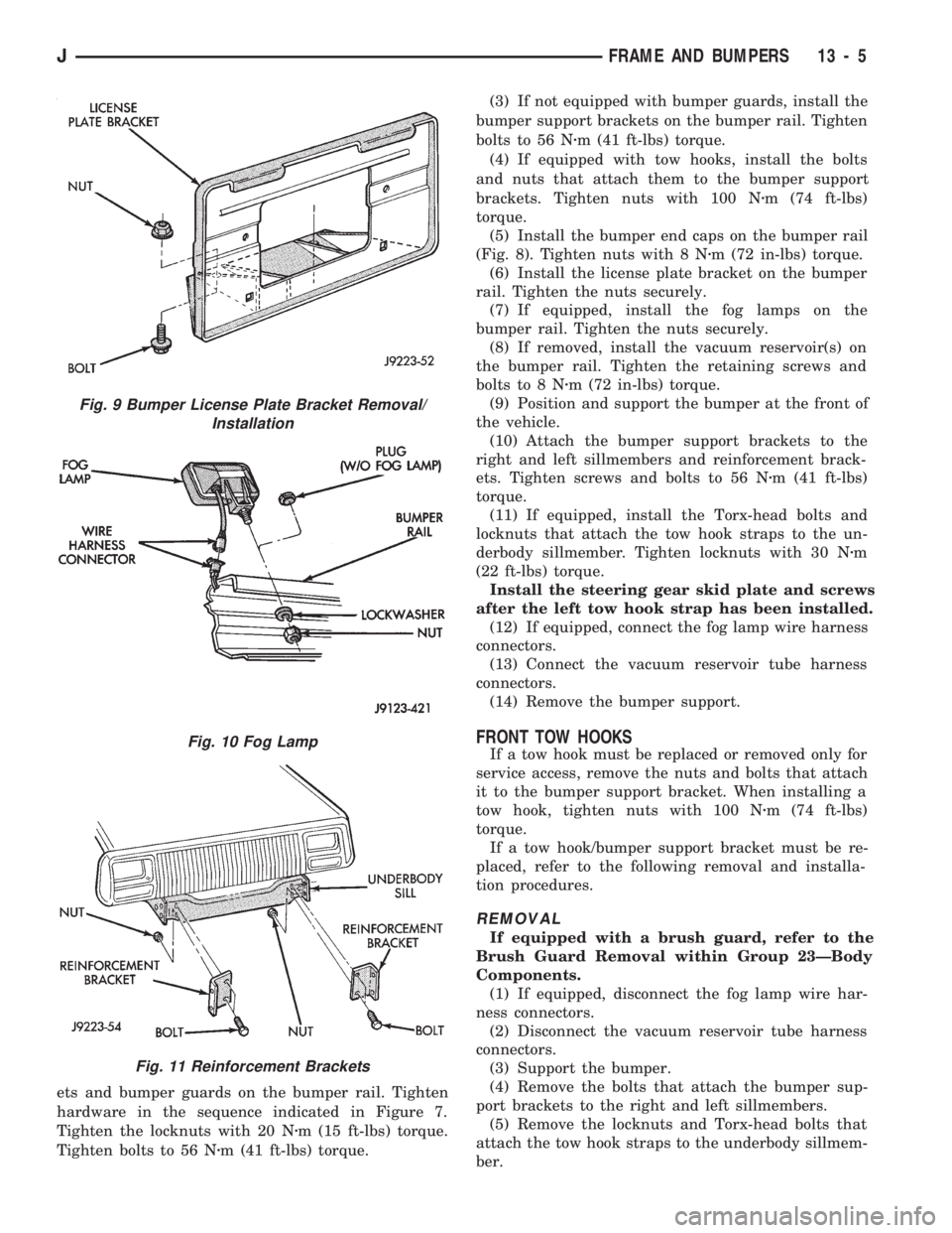
(11) Remove the license plate bracket (Fig. 9), if
equipped, from the bumper rail.
Fig. 1 Fog Lamp Wire Harness Connector
Fig. 2 Vacuum ReservoirÐLeft Side
Fig. 3 Vacuum ReservoirÐRight Side With Speed
Control Only
JFRAME AND BUMPERS 13 - 3
Page 945 of 1784
(12) If equipped, remove the fog lamps (Fig. 10)
from the bumper rail.
(13) If necessary, remove the vacuum reservoir(s)
from the bumper rail.
(14) If necessary, remove the sill crossmember re-
inforcement brackets from the sillmembers.
ASSEMBLY/INSTALLATION
(1) If removed, install the sill crossmember rein-
forcement brackets on the sillmembers (Fig. 11).
Tighten bolts to 56 Nzm (41 ft-lbs) torque.
(2) If equipped, install the bumper support brack-
Fig. 4 Tow Hook & StrapÐXJ Vehicles
Fig. 5 Front Bumper Removal/Installation
Fig. 6 Bumper Support Bracket Removal/Installation
Fig. 7 Bumper Guard Removal/Installation
Fig. 8 Bumper End Cap Removal/Installation
13 - 4 FRAME AND BUMPERSJ
Page 946 of 1784
ets and bumper guards on the bumper rail. Tighten
hardware in the sequence indicated in Figure 7.
Tighten the locknuts with 20 Nzm (15 ft-lbs) torque.
Tighten bolts to 56 Nzm (41 ft-lbs) torque.(3) If not equipped with bumper guards, install the
bumper support brackets on the bumper rail. Tighten
bolts to 56 Nzm (41 ft-lbs) torque.
(4) If equipped with tow hooks, install the bolts
and nuts that attach them to the bumper support
brackets. Tighten nuts with 100 Nzm (74 ft-lbs)
torque.
(5) Install the bumper end caps on the bumper rail
(Fig. 8). Tighten nuts with 8 Nzm (72 in-lbs) torque.
(6) Install the license plate bracket on the bumper
rail. Tighten the nuts securely.
(7) If equipped, install the fog lamps on the
bumper rail. Tighten the nuts securely.
(8) If removed, install the vacuum reservoir(s) on
the bumper rail. Tighten the retaining screws and
bolts to 8 Nzm (72 in-lbs) torque.
(9) Position and support the bumper at the front of
the vehicle.
(10) Attach the bumper support brackets to the
right and left sillmembers and reinforcement brack-
ets. Tighten screws and bolts to 56 Nzm (41 ft-lbs)
torque.
(11) If equipped, install the Torx-head bolts and
locknuts that attach the tow hook straps to the un-
derbody sillmember. Tighten locknuts with 30 Nzm
(22 ft-lbs) torque.
Install the steering gear skid plate and screws
after the left tow hook strap has been installed.
(12) If equipped, connect the fog lamp wire harness
connectors.
(13) Connect the vacuum reservoir tube harness
connectors.
(14) Remove the bumper support.
FRONT TOW HOOKS
If a tow hook must be replaced or removed only for
service access, remove the nuts and bolts that attach
it to the bumper support bracket. When installing a
tow hook, tighten nuts with 100 Nzm (74 ft-lbs)
torque.
If a tow hook/bumper support bracket must be re-
placed, refer to the following removal and installa-
tion procedures.
REMOVAL
If equipped with a brush guard, refer to the
Brush Guard Removal within Group 23ÐBody
Components.
(1) If equipped, disconnect the fog lamp wire har-
ness connectors.
(2) Disconnect the vacuum reservoir tube harness
connectors.
(3) Support the bumper.
(4) Remove the bolts that attach the bumper sup-
port brackets to the right and left sillmembers.
(5) Remove the locknuts and Torx-head bolts that
attach the tow hook straps to the underbody sillmem-
ber.
Fig. 9 Bumper License Plate Bracket Removal/
Installation
Fig. 10 Fog Lamp
Fig. 11 Reinforcement Brackets
JFRAME AND BUMPERS 13 - 5
Page 947 of 1784
The retaining screws and the steering gear
skid plate must be removed before the left strap
can be removed from the sillmember.
(6) Detach the tow hook straps from the sillmem-
ber.
(7) Remove the support and the bumper from the
vehicle.
(8) Remove the nuts and bolts that attach the tow
hooks to the bumper support brackets.
(9) Remove the tow hook from the bumper support
bracket (Fig. 4).
(10) Remove the support bracket from the bumper
rail.
INSTALLATION
(1) If equipped, install the bumper guard and
bumper support bracket on the bumper rail. Tighten
the retaining hardware in the sequence indicated in
Figure 7. Tighten locknuts to 20 Nzm (15 ft-lbs)
torque. Tighten bolts to 56 Nzm (41 ft-lbs) torque.
(2) If not equipped with bumper guards, install the
bumper support bracket on the bumper rail. Tighten
bolts to 56 Nzm (41 ft-lbs) torque.
(3) Position the tow hook at the support bracket.
Install the bolts and nuts that attach tow hook to the
bumper support bracket. (Fig. 4). Tighten nuts to 100
Nzm (74 ft-lbs) torque.
(4) Position and support the bumper at the front of
the vehicle.
(5) Attach the bumper support brackets to the
right and left sillmembers and reinforcement brack-
ets. Tighten screws and bolts to 56 Nzm (41 ft-lbs)
torque.
(6) If equipped, install the Torx-head bolts and
locknuts that attach the tow hook straps to the un-
derbody sillmember. Tighten locknuts to 30 Nzm (22
ft-lbs) torque.
Install the steering gear skid plate and screws
after the left tow hook strap has been installed.
(7) If equipped, connect the fog lamp wire harness
connectors. Connect the vacuum reservoir tube har-
ness connectors.
(8) Remove the bumper support.
REAR BUMPER
REMOVAL
(1) For vehicles equipped with a trailer hitch, re-
move the hitch before removing the bumper. If nec-
essary, refer to the removal procedure within Group
23ÐBody Components.
(2) Raise and support the rear of the vehicle.
(3) Support the bumper.
(4) Remove the bolts that attach the bumper sup-
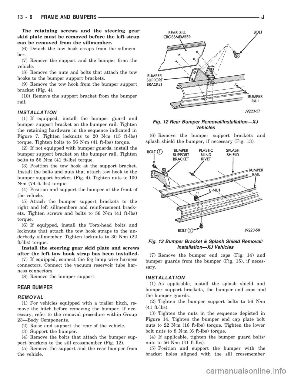
port brackets to the sill crossmember (Fig. 12).
(5) Remove the support and the rear bumper from
the vehicle.(6) Remove the bumper support brackets and
splash shield the bumper, if necessary (Fig. 13).
(7) Remove the bumper end caps (Fig. 14) and
bumper guards from the bumper (Fig. 15), if neces-
sary.
INSTALLATION
(1) As applicable, install the splash shield and
bumper support brackets, the bumper end caps and
the bumper guards.
(2) Tighten the bumper support bolts to 56 Nzm
(41 ft-lbs).
(3) Tighten the nuts in the sequence depicted in
Figure 14. Tighten the bumper end cap plate bolt
nuts to 22 Nzm (16 ft-lbs) torque. Tighten the lower
bolt nuts to 8 Nzm (6 ft-lbs) torque.
(4) If applicable, tighten the bumper guard bolts/
nuts to 56 Nzm (41 ft-lbs).
(5) Position and support the bumper with the
bracket holes aligned with the sill crossmember
Fig. 12 Rear Bumper Removal/InstallationÐXJ
Vehicles
Fig. 13 Bumper Bracket & Splash Shield Removal/
InstallationÐXJ Vehicles
13 - 6 FRAME AND BUMPERSJ
Page 951 of 1784

CONSTRUCTION
The frame is constructed of high-strength channel
steel siderails and crossmembers. The crossmembers
join the siderails and retain them in alignment in re-
lation to each other. This provides resistance to
frame twists and strains.
FRAME ALIGNMENT
INCORRECT ALIGNMENT
Incorrect frame alignment is usually a result of:
²collision impact, or
²the vehicle being operated with excessive loads, or
²loads not positioned in a properly distributed man-
ner on the vehicle.
A mis-aligned frame will affect front axle and/or
rear axle alignment. It can cause excessive wear and
mechanical failures in the powertrain. Window glass
cracks and door opening/closing problems. Vehicle
performance can also be impaired.
RE-ALIGNMENT
With collision damage, it is important that the ex-
istence of any frame alignment damage be deter-
mined. If necessary, the frame should be correctly re-
aligned. Refer to the reference dimensions listed on
frame alignment dimension chart (Fig. 4).
FRAME INSPECTION/MEASUREMENTS
INSPECTION
Before proceeding with measurements, inspect all
components for visible damage and other metal dam-
age. Also, inspect all connections for loose and miss-
ing hardware.
All damaged areas must be repaired and/or the
components replaced, as necessary.
MEASUREMENTS
Measure the frame for mis-alignment with the
body attached to the frame. Figure 4 provides the
alignment reference dimensions. The following infor-
mation applies to all measurements.
(1) Place the vehicle on a level surface.
(2) If the vehicle is loaded, ensure that the vehicle
weight plus the payload does not exceed the gross ve-
hicle weight rating. Also, ensure that the load is dis-
tributed in the vehicle as evenly as possible.
(3) Measure the tire inflation pressures and adjust
the pressure, if necessary.
HORIZONTAL OR DIAGONAL FRAME MEASUREMENTS
Determine the frame horizontal non-square devia-
tion(s) according to the following procedure.
(1) Select several reference points along one frame
siderail, preferably at the crossmember junctions.(2) Transfer these reference points to the surface/
floor with a plumb bob. Paper sheets can be attached
to the surface below the reference points for better
measurement accuracy.
(3) Locate the reference points on the other frame
siderail and transfer them to the surface/floor with
the same procedure as above.
(4) Move the vehicle away and measure between
all the reference points diagonally from and parallel
to the siderails (Fig. 5). The measurements should
not differ by more than 6 mm (1/4 in).
(5) Measure the distance between the two front
reference points and the distance between the two
rear reference points. Divide each distance in half
and indicate the two half-way points on the surface/
floor. Designate the front point as ``1'' and the rear
point as ``2'' (Fig. 5).
(6) Place a chalk-line between points 1 and 2 and
``snap'' the string.
(7) Determine how close the center line is to the
diagonal intersection points A, B, C, D, E, and F in
Figure 5.
(8) The reference marks on the surface/floor will
provide an illustrated indication of the degree of
frame misalignment.
(9) A reference point transferred from one frame
siderail may be 3 mm (1/8 in) ahead or behind the
reference point from the opposite siderail.
(10) Frame bow to the side should not exceed 3
mm per 2,540 mm (1/8 inch per 100 inches) in
length.
(11) The overall width of the frame should not
vary more than 3 mm (1/8 in) from reference point-
to-reference point.
(12) Repeat steps (1) through (11) after straighten-
ing the frame to evaluate the effectiveness.
TWIST AND PARALLEL FRAME MEASUREMENTS
Determine the amount of frame twist and siderail
deviation according to the following procedure.
(1) Mark the vertical measurement reference
points under the frame siderails at 305-mm (12-in)
intervals starting at the rear frame crossmember.
(2) Measure the vertical distance up from a level
surface to each reference point located under the left
and right frame siderails.
(3) The distance to a reference point under one
frame siderail should be 3 mm (1/8 in) greater or less
than the point under the opposite siderail.
(4) Plot the measured vertical distances to scale on
a sheet of graph paper. Plot the distances so that the
frame siderails are located adjacent to each other.
Join the vertical distance points.
13 - 10 FRAME AND BUMPERSJ
Page 955 of 1784

YJ BUMPERS AND FRAME ATTACHED COMPONENTS
INDEX
page page
Generator Splash Shield................... 14
Body.................................. 18
Engine Front Support Cushion............... 15
Frame Crossmember Cover................. 14
Front Bumper........................... 14
Fuel and Brake Fluid Tube Retainer Clip....... 16
Fuel Filter Shield and Bracket............... 17
Fuel Tank Skid Plate...................... 16Muffler and Tailpipe Heat Shields............ 17
Muffler/Tailpipe Hanger Bracket.............. 16
Rear Bumper............................ 18
Rear Jounce Bumper..................... 18
Service Information....................... 14
Tow Hooks............................. 14
Transfer Case Skid Plate.................. 15
SERVICE INFORMATION
In some cases, components in the following proce-
dures either support, or are hidden by other compo-
nents.
FRONT BUMPER
The YJ front bumper is a one-piece rail (Fig. 1). A
front crossmember cover (Fig. 1) is also installed on
all YJ vehicles.
BUMPER REMOVAL
(1) Disconnect and remove the fog lamps, if
equipped.
(2) Remove the nuts and bolts that retain the
bumper extensions to the bumper rail and remove
the extensions.
(3) Remove the nuts and bolts that attach the
bumper rail/tow hooks to the frame rails.(4) Remove the bumper rail from the frame rails.
BUMPER INSTALLATION
(1) Position the front bumper on the frame rails.
(2) Install the bolts and attach the front bumper
rail (and tow hooks, if equipped) to the frame rails.
(3) Tighten the bolts to 102 Nzm (75 ft-lbs) torque.
(4) Position the bumper extensions on the bumper
rail and install the retaining bolts.
(5) Tighten the bolts to 104 Nzm (77 ft-lbs) torque.
(6) Install the fog lamps, if equipped.
FRAME CROSSMEMBER COVER
REMOVAL
(1) Remove the screws that attach the crossmem-
ber cover and support to the frame rails.
(2) Remove the crossmember cover and support
from the frame rails.
INSTALLATION
(1) Position the support and crossmember cover on
the frame rails.
(2) Install the attaching screws.
(3) Tighten the screws to 8 Nzm (72 in-lbs) torque.
TOW HOOKS
REMOVAL
(1) Remove the two bolts that attach the tow hook
to the bumper rail and to the frame rail.
(2) Remove the tow hook.
INSTALLATION
(1) Position the tow hook on the bumper rail and
frame rail.
(2) Install the attaching bolts.
(3) Tighten the bolts to 102 Nzm (75 ft-lbs) torque.
GENERATOR SPLASH SHIELD
REMOVAL
(1) Remove the shield retaining nut and washer
(Fig. 2) from the engine oil pan stud (2.5L engines
only).
Fig. 1 Front Bumper Rail, Crossmember Cover &
Tow Hooks
13 - 14 FRAME AND BUMPERSJ
Page 956 of 1784
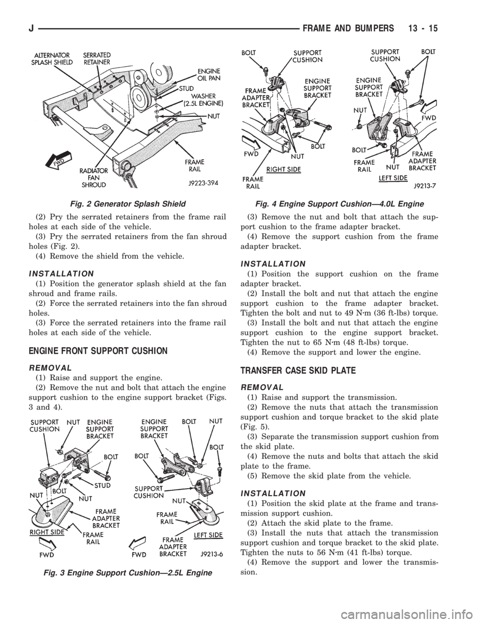
(2) Pry the serrated retainers from the frame rail
holes at each side of the vehicle.
(3) Pry the serrated retainers from the fan shroud
holes (Fig. 2).
(4) Remove the shield from the vehicle.
INSTALLATION
(1) Position the generator splash shield at the fan
shroud and frame rails.
(2) Force the serrated retainers into the fan shroud
holes.
(3) Force the serrated retainers into the frame rail
holes at each side of the vehicle.
ENGINE FRONT SUPPORT CUSHION
REMOVAL
(1) Raise and support the engine.
(2) Remove the nut and bolt that attach the engine
support cushion to the engine support bracket (Figs.
3 and 4).(3) Remove the nut and bolt that attach the sup-
port cushion to the frame adapter bracket.
(4) Remove the support cushion from the frame
adapter bracket.
INSTALLATION
(1) Position the support cushion on the frame
adapter bracket.
(2) Install the bolt and nut that attach the engine
support cushion to the frame adapter bracket.
Tighten the bolt and nut to 49 Nzm (36 ft-lbs) torque.
(3) Install the bolt and nut that attach the engine
support cushion to the engine support bracket.
Tighten the nut to 65 Nzm (48 ft-lbs) torque.
(4) Remove the support and lower the engine.
TRANSFER CASE SKID PLATE
REMOVAL
(1) Raise and support the transmission.
(2) Remove the nuts that attach the transmission
support cushion and torque bracket to the skid plate
(Fig. 5).
(3) Separate the transmission support cushion from
the skid plate.
(4) Remove the nuts and bolts that attach the skid
plate to the frame.
(5) Remove the skid plate from the vehicle.
INSTALLATION
(1) Position the skid plate at the frame and trans-
mission support cushion.
(2) Attach the skid plate to the frame.
(3) Install the nuts that attach the transmission
support cushion and torque bracket to the skid plate.
Tighten the nuts to 56 Nzm (41 ft-lbs) torque.
(4) Remove the support and lower the transmis-
sion.
Fig. 2 Generator Splash Shield
Fig. 3 Engine Support CushionÐ2.5L Engine
Fig. 4 Engine Support CushionÐ4.0L Engine
JFRAME AND BUMPERS 13 - 15
Page 961 of 1784
(1) Disconnect the battery negative cable.
(2) Disconnect all wire harness connectors that
connect body wire harnesses to the frame wire har-
nesses.
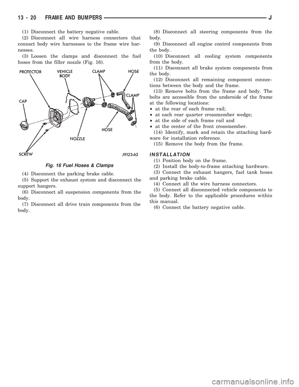
(3) Loosen the clamps and disconnect the fuel
hoses from the filler nozzle (Fig. 16).
(4) Disconnect the parking brake cable.
(5) Support the exhaust system and disconnect the
support hangers.
(6) Disconnect all suspension components from the
body.
(7) Disconnect all drive train components from the
body.(8) Disconnect all steering components from the
body.
(9) Disconnect all engine control components from
the body.
(10) Disconnect all cooling system components
from the body.
(11) Disconnect all brake system components from
the body.
(12) Disconnect all remaining component connec-
tions between the body and the frame.
(13) Remove bolts from the frame and body. The
bolts are accessible from the underside of the frame
at the following locations:
²at the rear of each frame rail;
²at each rear quarter crossmember wedge;
²at the side of each frame rail and
²at the center of the front crossmember.
(14) Identify, mark and retain the attaching hard-
ware for installation reference.
(15) Remove the body from the frame.
INSTALLATION
(1) Position body on the frame.
(2) Install the body-to-frame attaching hardware.
(3) Connect the exhaust hangers, fuel tank hoses
and parking brake cable.
(4) Connect all the wire harness connectors.
(5) Connect all disconnected vehicle components to
the body. Refer to the applicable procedures within
this manual.
(6) Connect the battery negative cable.
Fig. 16 Fuel Hoses & Clamps
13 - 20 FRAME AND BUMPERSJ