1994 JEEP CHEROKEE front
[x] Cancel search: frontPage 1085 of 1784
(11) Disconnect the following items from the steer-
ing column connectors:
²Ignition switch wire harness
²Dimmer switch wire harness
²Turn signal switch wire harness
²Windshield wiper wire harness
²Cruise control wire harness (if equipped)
²Park-lock cable (if equipped)
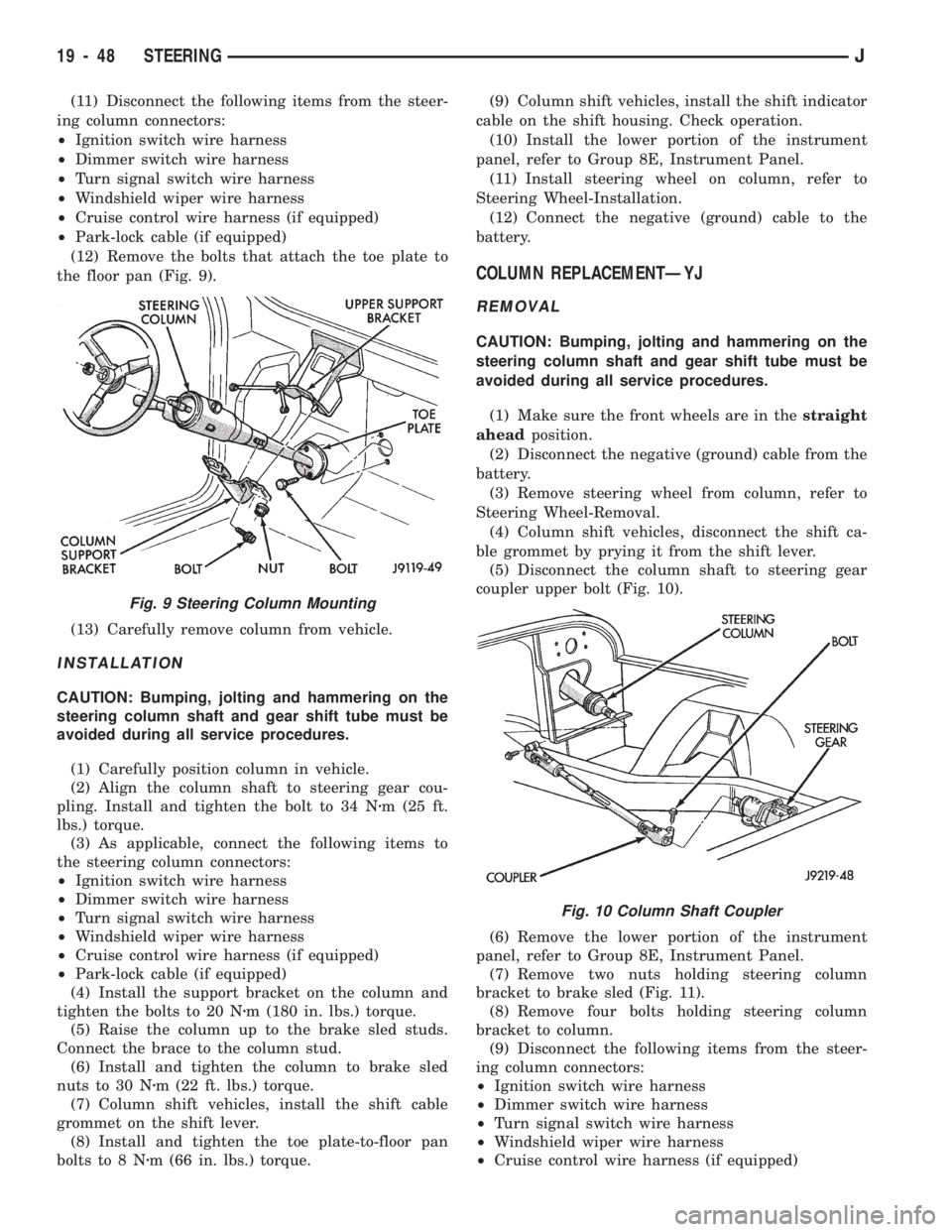
(12) Remove the bolts that attach the toe plate to
the floor pan (Fig. 9).
(13) Carefully remove column from vehicle.
INSTALLATION
CAUTION: Bumping, jolting and hammering on the
steering column shaft and gear shift tube must be
avoided during all service procedures.
(1) Carefully position column in vehicle.
(2) Align the column shaft to steering gear cou-
pling. Install and tighten the bolt to 34 Nzm (25 ft.
lbs.) torque.
(3) As applicable, connect the following items to
the steering column connectors:
²Ignition switch wire harness
²Dimmer switch wire harness
²Turn signal switch wire harness
²Windshield wiper wire harness
²Cruise control wire harness (if equipped)
²Park-lock cable (if equipped)
(4) Install the support bracket on the column and
tighten the bolts to 20 Nzm (180 in. lbs.) torque.
(5) Raise the column up to the brake sled studs.
Connect the brace to the column stud.
(6) Install and tighten the column to brake sled
nuts to 30 Nzm (22 ft. lbs.) torque.
(7) Column shift vehicles, install the shift cable
grommet on the shift lever.
(8) Install and tighten the toe plate-to-floor pan
bolts to 8 Nzm (66 in. lbs.) torque.(9) Column shift vehicles, install the shift indicator
cable on the shift housing. Check operation.
(10) Install the lower portion of the instrument
panel, refer to Group 8E, Instrument Panel.
(11) Install steering wheel on column, refer to
Steering Wheel-Installation.
(12) Connect the negative (ground) cable to the
battery.
COLUMN REPLACEMENTÐYJ
REMOVAL
CAUTION: Bumping, jolting and hammering on the
steering column shaft and gear shift tube must be
avoided during all service procedures.
(1) Make sure the front wheels are in thestraight
aheadposition.
(2) Disconnect the negative (ground) cable from the
battery.
(3) Remove steering wheel from column, refer to
Steering Wheel-Removal.
(4) Column shift vehicles, disconnect the shift ca-
ble grommet by prying it from the shift lever.
(5) Disconnect the column shaft to steering gear
coupler upper bolt (Fig. 10).
(6) Remove the lower portion of the instrument
panel, refer to Group 8E, Instrument Panel.
(7) Remove two nuts holding steering column
bracket to brake sled (Fig. 11).
(8) Remove four bolts holding steering column
bracket to column.
(9) Disconnect the following items from the steer-
ing column connectors:
²Ignition switch wire harness
²Dimmer switch wire harness
²Turn signal switch wire harness
²Windshield wiper wire harness
²Cruise control wire harness (if equipped)
Fig. 9 Steering Column Mounting
Fig. 10 Column Shaft Coupler
19 - 48 STEERINGJ
Page 1091 of 1784
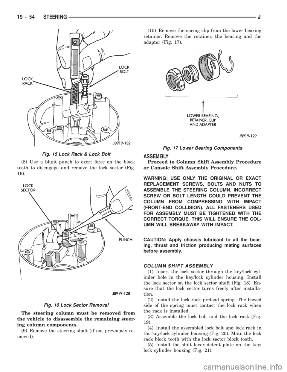
(8) Use a blunt punch to exert force on the block
tooth to disengage and remove the lock sector (Fig.
16).
The steering column must be removed from
the vehicle to disassemble the remaining steer-
ing column components.
(9) Remove the steering shaft (if not previously re-
moved).(10) Remove the spring clip from the lower bearing
retainer. Remove the retainer, the bearing and the
adapter (Fig. 17).
ASSEMBLY
Proceed to Column Shift Assembly Procedure
or Console Shift Assembly Procedure.
WARNING: USE ONLY THE ORIGINAL OR EXACT
REPLACEMENT SCREWS, BOLTS AND NUTS TO
ASSEMBLE THE STEERING COLUMN. INCORRECT
SCREW OR BOLT LENGTH COULD PREVENT THE
COLUMN FROM COMPRESSING WITH IMPACT
(FRONT-END COLLISION). ALL FASTENERS USED
FOR ASSEMBLY MUST BE TIGHTENED WITH THE
CORRECT TORQUE. THIS WILL ENSURE THE COL-
UMN WILL BREAKAWAY WITH IMPACT.
CAUTION: Apply chassis lubricant to all the bear-
ing, thrust and friction producing mating surfaces
before assembly.
COLUMN SHIFT ASSEMBLY
(1) Insert the lock sector through the key/lock cyl-
inder hole in the key/lock cylinder housing. Install
the lock sector on the lock sector shaft (Fig. 18). En-
sure that the lock sector turns freely after installa-
tion.
(2) Install the lock rack preload spring. The bowed
side of the spring must contact the lock rack when
the rack is installed.
(3) Assemble the lock bolt and the lock rack (Fig.
19).
(4) Install the assembled lock bolt and lock rack in
the key/lock cylinder housing (Fig. 20). Mate the lock
rack block tooth with the lock sector block tooth.
(5) Install the shift lever detent plate on the key/
lock cylinder housing (Fig. 21).
Fig. 17 Lower Bearing Components
Fig. 15 Lock Rack & Lock Bolt
Fig. 16 Lock Sector Removal
19 - 54 STEERINGJ
Page 1096 of 1784
TILT STEERING COLUMN
DISASSEMBLY
(1) Remove the steering column from the vehicle,
if necessary. Refer to the removal procedure.
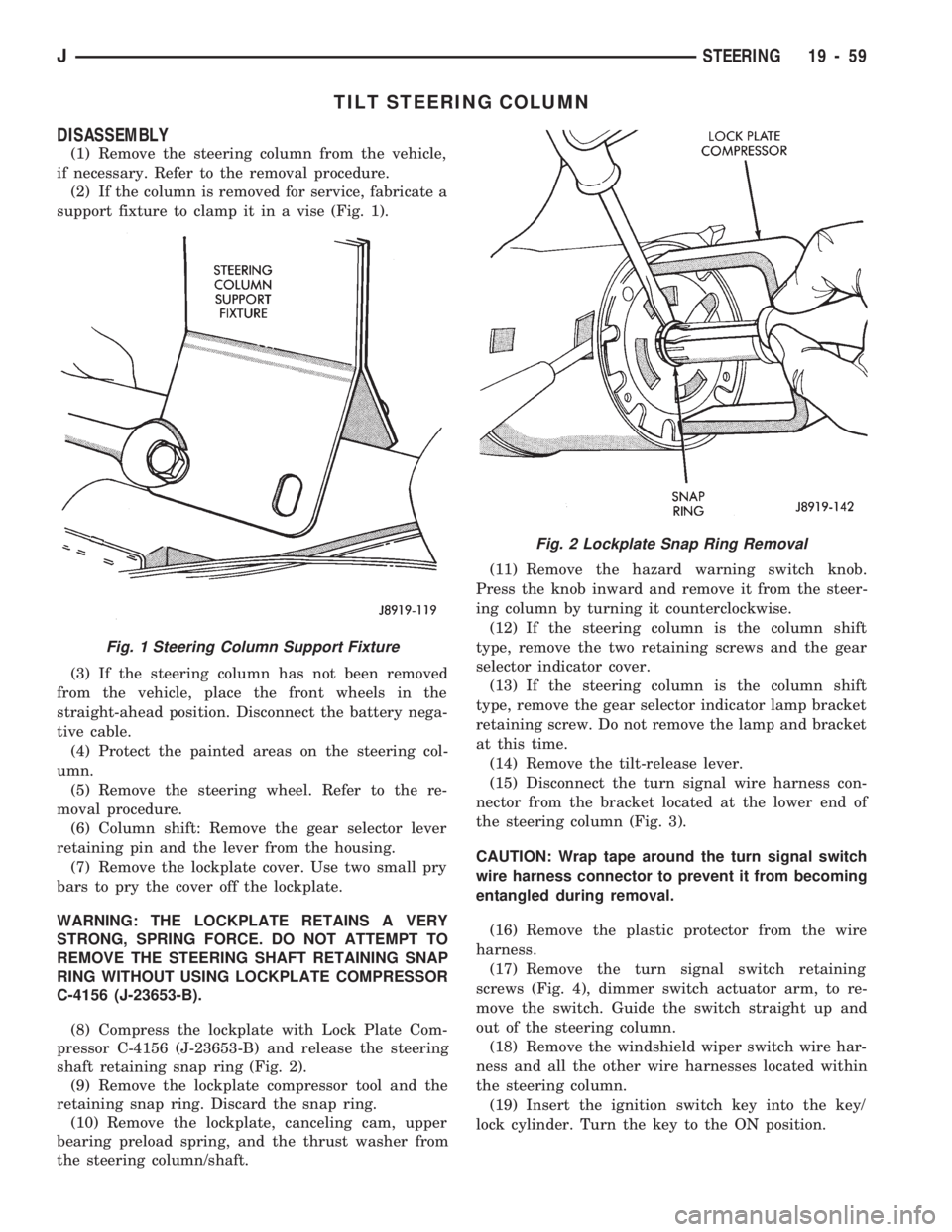
(2) If the column is removed for service, fabricate a
support fixture to clamp it in a vise (Fig. 1).
(3) If the steering column has not been removed
from the vehicle, place the front wheels in the
straight-ahead position. Disconnect the battery nega-
tive cable.
(4) Protect the painted areas on the steering col-
umn.
(5) Remove the steering wheel. Refer to the re-
moval procedure.
(6) Column shift: Remove the gear selector lever
retaining pin and the lever from the housing.
(7) Remove the lockplate cover. Use two small pry
bars to pry the cover off the lockplate.
WARNING: THE LOCKPLATE RETAINS A VERY
STRONG, SPRING FORCE. DO NOT ATTEMPT TO
REMOVE THE STEERING SHAFT RETAINING SNAP
RING WITHOUT USING LOCKPLATE COMPRESSOR
C-4156 (J-23653-B).
(8) Compress the lockplate with Lock Plate Com-
pressor C-4156 (J-23653-B) and release the steering
shaft retaining snap ring (Fig. 2).
(9) Remove the lockplate compressor tool and the
retaining snap ring. Discard the snap ring.
(10) Remove the lockplate, canceling cam, upper
bearing preload spring, and the thrust washer from
the steering column/shaft.(11) Remove the hazard warning switch knob.
Press the knob inward and remove it from the steer-
ing column by turning it counterclockwise.
(12) If the steering column is the column shift
type, remove the two retaining screws and the gear
selector indicator cover.
(13) If the steering column is the column shift
type, remove the gear selector indicator lamp bracket
retaining screw. Do not remove the lamp and bracket
at this time.
(14) Remove the tilt-release lever.
(15) Disconnect the turn signal wire harness con-
nector from the bracket located at the lower end of
the steering column (Fig. 3).
CAUTION: Wrap tape around the turn signal switch
wire harness connector to prevent it from becoming
entangled during removal.
(16) Remove the plastic protector from the wire
harness.
(17) Remove the turn signal switch retaining
screws (Fig. 4), dimmer switch actuator arm, to re-
move the switch. Guide the switch straight up and
out of the steering column.
(18) Remove the windshield wiper switch wire har-
ness and all the other wire harnesses located within
the steering column.
(19) Insert the ignition switch key into the key/
lock cylinder. Turn the key to the ON position.
Fig. 1 Steering Column Support Fixture
Fig. 2 Lockplate Snap Ring Removal
JSTEERING 19 - 59
Page 1101 of 1784
ASSEMBLY
WARNING: USE ONLY THE ORIGINAL OR EXACT
REPLACEMENT SCREWS, BOLTS AND NUTS TO
ASSEMBLE THE STEERING COLUMN. INCORRECT
SCREW OR BOLT LENGTH COULD PREVENT THE
COLUMN FROM COMPRESSING WITH IMPACT
(FRONT-END COLLISION). ALL FASTENERS USED
FOR ASSEMBLY MUST BE TIGHTENED WITH THE
CORRECT TORQUE. THIS WILL ENSURE THE COL-
UMN WILL BREAKAWAY WITH IMPACT.CAUTION: Apply chassis lubricant to all the bear-
ing, thrust and friction producing mating surfaces
before assembly.
COLUMN SHIFT ASSEMBLY
(1) Install the shift bowl on the steering column
jacket.
(2) Install the shift tube spring, wave washer and
retainer plate in the shift bowl.
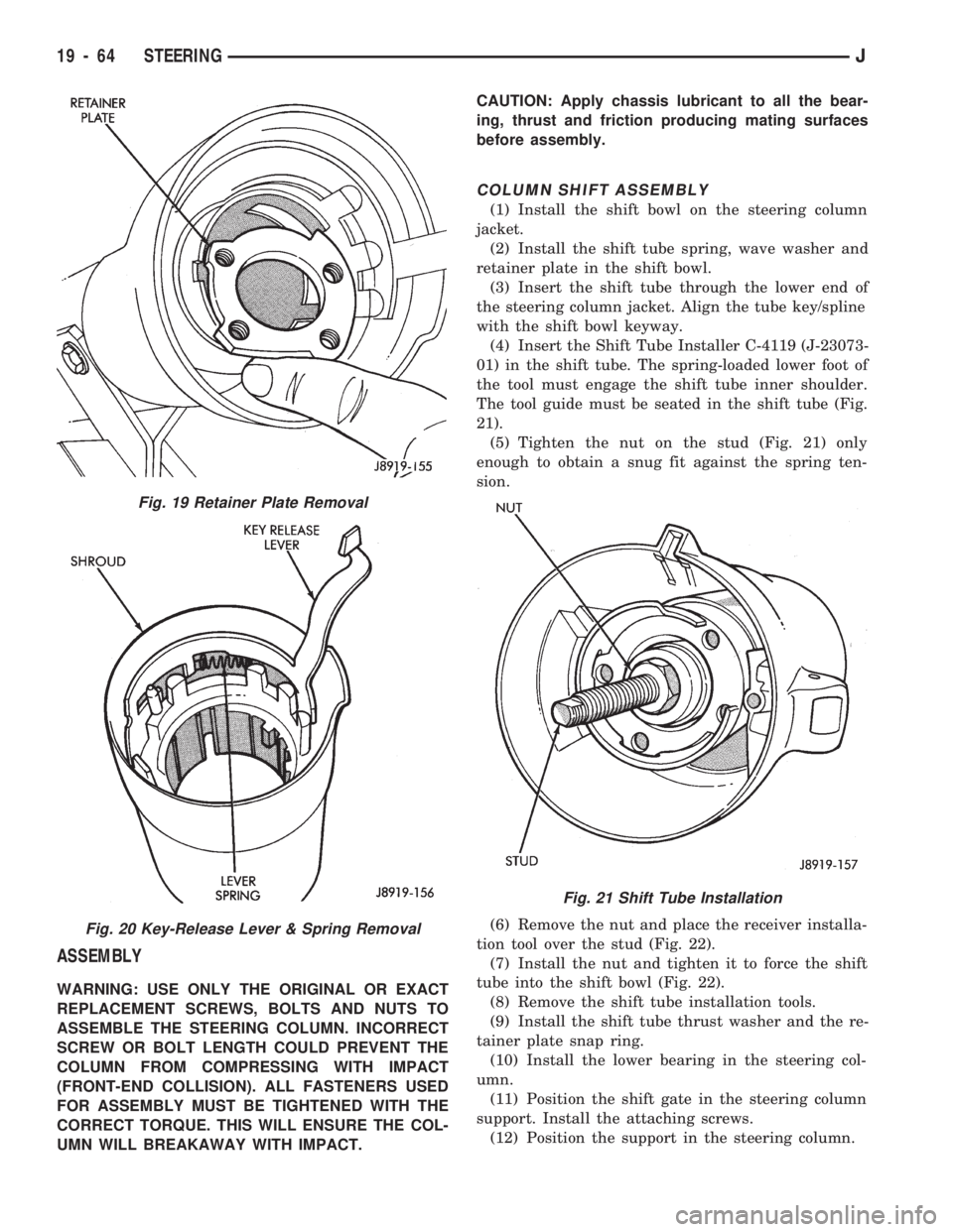
(3) Insert the shift tube through the lower end of
the steering column jacket. Align the tube key/spline
with the shift bowl keyway.
(4) Insert the Shift Tube Installer C-4119 (J-23073-
01) in the shift tube. The spring-loaded lower foot of
the tool must engage the shift tube inner shoulder.
The tool guide must be seated in the shift tube (Fig.
21).
(5) Tighten the nut on the stud (Fig. 21) only
enough to obtain a snug fit against the spring ten-
sion.
(6) Remove the nut and place the receiver installa-
tion tool over the stud (Fig. 22).
(7) Install the nut and tighten it to force the shift
tube into the shift bowl (Fig. 22).
(8) Remove the shift tube installation tools.
(9) Install the shift tube thrust washer and the re-
tainer plate snap ring.
(10) Install the lower bearing in the steering col-
umn.
(11) Position the shift gate in the steering column
support. Install the attaching screws.
(12) Position the support in the steering column.
Fig. 19 Retainer Plate Removal
Fig. 20 Key-Release Lever & Spring Removal
Fig. 21 Shift Tube Installation
19 - 64 STEERINGJ
Page 1108 of 1784
PUMP REPLACEMENT
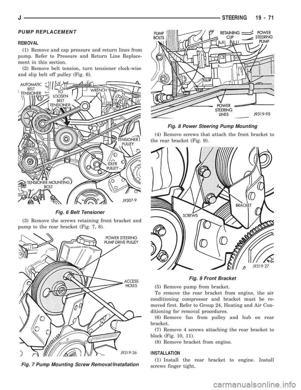
REMOVAL
(1) Remove and cap pressure and return lines from
pump. Refer to Pressure and Return Line Replace-
ment in this section.
(2) Remove belt tension, turn tensioner clock-wise
and slip belt off pulley (Fig. 6).
(3) Remove the screws retaining front bracket and
pump to the rear bracket (Fig. 7, 8).(4) Remove screws that attach the front bracket to
the rear bracket (Fig. 9).
(5) Remove pump from bracket.
To remove the rear bracket from engine, the air
conditioning compressor and bracket must be re-
moved first. Refer to Group 24, Heating and Air Con-
ditioning for removal procedures.
(6) Remove fan from pulley and hub on rear
bracket.
(7) Remove 4 screws attaching the rear bracket to
block (Fig. 10, 11).
(8) Remove bracket from engine.
INSTALLATION
(1) Install the rear bracket to engine. Install
screws finger tight.
Fig. 6 Belt Tensioner
Fig. 7 Pump Mounting Screw Removal/Installation
Fig. 8 Power Steering Pump Mounting
Fig. 9 Front Bracket
JSTEERING 19 - 71
Page 1109 of 1784
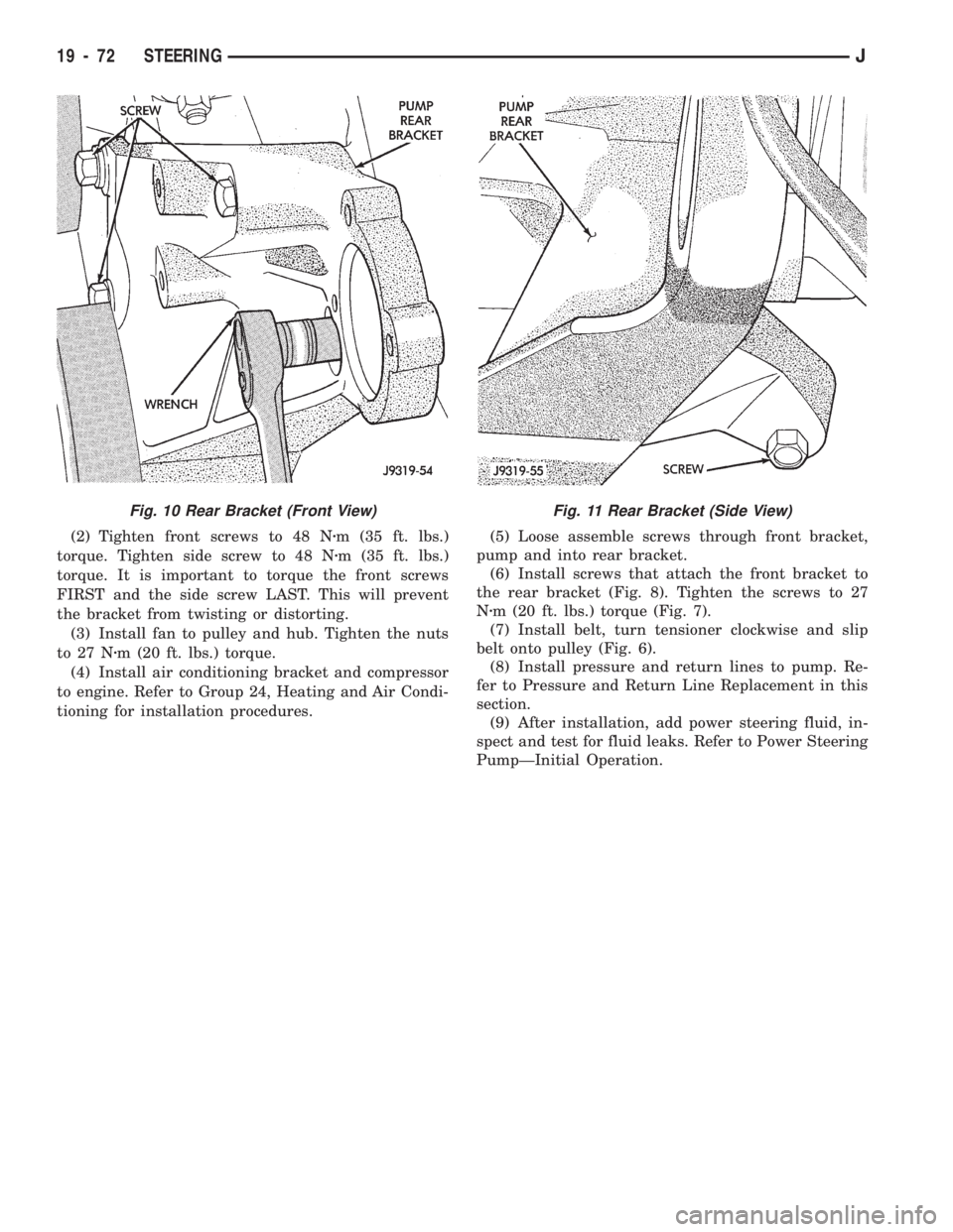
(2) Tighten front screws to 48 Nzm (35 ft. lbs.)
torque. Tighten side screw to 48 Nzm (35 ft. lbs.)
torque. It is important to torque the front screws
FIRST and the side screw LAST. This will prevent
the bracket from twisting or distorting.
(3) Install fan to pulley and hub. Tighten the nuts
to 27 Nzm (20 ft. lbs.) torque.
(4) Install air conditioning bracket and compressor
to engine. Refer to Group 24, Heating and Air Condi-
tioning for installation procedures.(5) Loose assemble screws through front bracket,
pump and into rear bracket.
(6) Install screws that attach the front bracket to
the rear bracket (Fig. 8). Tighten the screws to 27
Nzm (20 ft. lbs.) torque (Fig. 7).
(7) Install belt, turn tensioner clockwise and slip
belt onto pulley (Fig. 6).
(8) Install pressure and return lines to pump. Re-
fer to Pressure and Return Line Replacement in this
section.
(9) After installation, add power steering fluid, in-
spect and test for fluid leaks. Refer to Power Steering
PumpÐInitial Operation.
Fig. 11 Rear Bracket (Side View)Fig. 10 Rear Bracket (Front View)
19 - 72 STEERINGJ
Page 1113 of 1784
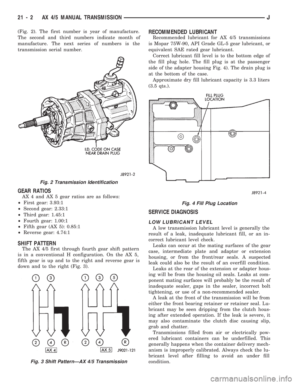
(Fig. 2). The first number is year of manufacture.
The second and third numbers indicate month of
manufacture. The next series of numbers is the
transmission serial number.
GEAR RATIOS
AX 4 and AX 5 gear ratios are as follows:
²First gear: 3.93:1
²Second gear: 2.33:1
²Third gear: 1.45:1
²Fourth gear: 1.00:1
²Fifth gear (AX 5): 0.85:1
²Reverse gear: 4.74:1
SHIFT PATTERN
The AX 4/5 first through fourth gear shift pattern
is in a conventional H configuration. On the AX 5,
fifth gear is up and to the right and reverse gear is
down and to the right (Fig. 3).
RECOMMENDED LUBRICANT
Recommended lubricant for AX 4/5 transmissions
is Mopar 75W-90, API Grade GL-5 gear lubricant, or
equivalent SAE rated gear lubricant.
Correct lubricant fill level is to the bottom edge of
the fill plug hole. The fill plug is at the passenger
side of the adapter housing Fig. 4). The drain plug is
at the bottom of the case.
Approximate dry fill lubricant capacity is 3.3 liters
(3.5 qts.).
SERVICE DIAGNOSIS
LOW LUBRICANT LEVEL
A low transmission lubricant level is generally the
result of a leak, inadequate lubricant fill, or an in-
correct lubricant level check.
Leaks can occur at the mating surfaces of the gear
case, intermediate plate and adaptor or extension
housing, or from the front/rear seals. A suspected
leak could also be the result of an overfill condition.
Leaks at the rear of the extension or adapter hous-
ing will be from the housing oil seals. Leaks at com-
ponent mating surfaces will probably be the result of
inadequate sealer, gaps in the sealer, incorrect bolt
tightening, or use of a non-recommended sealer.
A leak at the front of the transmission will be from
either the front bearing retainer or retainer seal. Lu-
bricant may be seen dripping from the clutch hous-
ing after extended operation. If the leak is severe, it
may also contaminate the clutch disc causing slip,
grab and chatter.
Transmissions filled from air or electrically pow-
ered lubricant containers can be underfilled. This
generally happens when the container delivery mech-
anism is improperly calibrated. Always check the lu-
bricant level after filling to avoid an under fill
condition.
Fig. 2 Transmission Identification
Fig. 3 Shift PatternÐAX 4/5 Transmission
Fig. 4 Fill Plug Location
21 - 2 AX 4/5 MANUAL TRANSMISSIONJ
Page 1115 of 1784
(6) Remove slave cylinder from clutch housing.
(7) Disconnect transmission shift lever as follows:
(a) Lower transmission-transfer case assembly ap-
proximately 7-8 cm (3 in.) for access to shift lever.
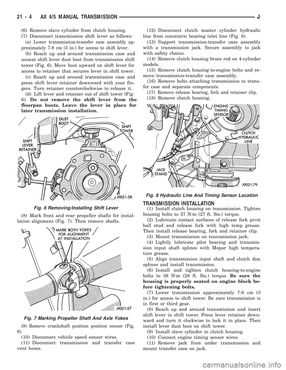
(b) Reach up and around transmission case and
unseat shift lever dust boot from transmission shift
tower (Fig. 6). Move boot upward on shift lever for
access to retainer that secures lever in shift tower.
(c) Reach up and around transmission case and
press shift lever retainer downward with your fin-
gers. Turn retainer counterclockwise to release it.
(d) Lift lever and retainer out of shift tower (Fig.
6).Do not remove the shift lever from the
floorpan boots. Leave the lever in place for
later transmission installation.
(8) Mark front and rear propeller shafts for instal-
lation alignment (Fig. 7). Then remove shafts.
(9) Remove crankshaft position position sensor (Fig.
8).
(10) Disconnect vehicle speed sensor wires.
(11) Disconnect transmission and transfer case
vent hoses.(12) Disconnect clutch master cylinder hydraulic
line from concentric bearing inlet line (Fig. 8).
(13) Support transmission-transfer case assembly
with a transmission jack. Secure assembly to jack
with safety chains.
(14) Remove clutch housing brace rod on 4-cylinder
models.
(15) Remove clutch housing-to-engine bolts and re-
move transmission-transfer case assembly.
(16) Remove bolts attaching transmission to trans-
fer case and separate components.
(17) Remove release bearing, fork and retainer clip.
(18) Remove clutch housing.
TRANSMISSION INSTALLATION
(1) Install clutch housing on transmission. Tighten
housing bolts to 37 Nzm (27 ft. lbs.) torque.
(2) Lubricate contact surfaces of release fork pivot
ball stud and release fork with high temp grease.
Then install release bearing, fork and retainer clip.
(3) Mount transmission on transmission jack.
(4) Lightly lubricate pilot bearing and transmis-
sion input shaft splines with Mopar high tempera-
ture grease.
(5) Align transmission input shaft and clutch disc
splines and install transmission.
(6) Install and tighten clutch housing-to-engine
bolts to 38 Nzm (28 ft. lbs.) torque.Be sure the
housing is properly seated on engine block be-
fore tightening bolts.
(7) Lower transmission approximately 7-8 cm (3
in.) for access to shift tower. Be sure transmission is
in first or third gear.
(8) Reach up and around transmission and insert
shift lever in shift tower. Press lever retainer down-
ward and turn it clockwise to lock it in place. Then
install lever dust boot on shift tower.
(9) Install slave cylinder in clutch housing.
(10) Connect engine timing sensor wires.
(11) Remove jack from under transmission and
mount transfer case on jack.Fig. 6 Removing/Installing Shift Lever
Fig. 7 Marking Propeller Shaft And Axle Yokes
Fig. 8 Hydraulic Line And Timing Sensor Location
21 - 4 AX 4/5 MANUAL TRANSMISSIONJ