Page 1378 of 1784

outer diameter is 47.2 mm (1.858 in.) and inside di-
ameter is 28.1 mm (1.106 in.).
(66) Lubricate and install replacement O-ring on
oil pump body.
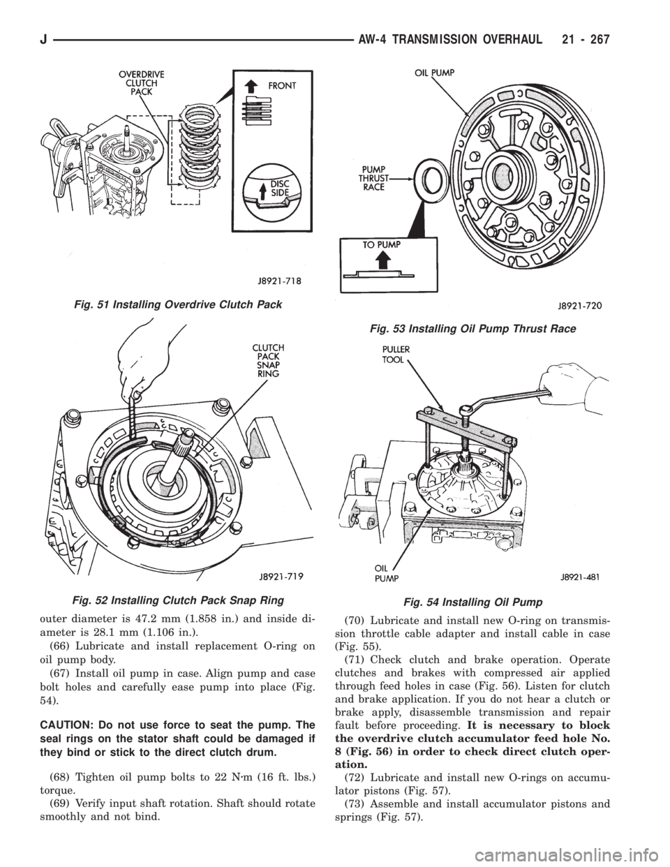
(67) Install oil pump in case. Align pump and case
bolt holes and carefully ease pump into place (Fig.
54).
CAUTION: Do not use force to seat the pump. The
seal rings on the stator shaft could be damaged if
they bind or stick to the direct clutch drum.
(68) Tighten oil pump bolts to 22 Nzm (16 ft. lbs.)
torque.
(69) Verify input shaft rotation. Shaft should rotate
smoothly and not bind.(70) Lubricate and install new O-ring on transmis-
sion throttle cable adapter and install cable in case
(Fig. 55).
(71) Check clutch and brake operation. Operate
clutches and brakes with compressed air applied
through feed holes in case (Fig. 56). Listen for clutch
and brake application. If you do not hear a clutch or
brake apply, disassemble transmission and repair
fault before proceeding.It is necessary to block
the overdrive clutch accumulator feed hole No.
8 (Fig. 56) in order to check direct clutch oper-
ation.
(72) Lubricate and install new O-rings on accumu-
lator pistons (Fig. 57).
(73) Assemble and install accumulator pistons and
springs (Fig. 57).
Fig. 53 Installing Oil Pump Thrust Race
Fig. 54 Installing Oil Pump
Fig. 51 Installing Overdrive Clutch Pack
Fig. 52 Installing Clutch Pack Snap Ring
JAW-4 TRANSMISSION OVERHAUL 21 - 267
Page 1379 of 1784
(74) Install new check ball body and spring (Fig.
58).
(75) Position valve body on case (Fig. 59).
(76) Install detent spring (Fig. 59).
(77) Align manual valve, detent spring and shift
sector (Fig. 59).
(78) Connect transmission throttle cable to throttle
valve cam (Fig. 60).
(79) Install and tighten valve body-to-case bolts to
10 Nzm (7 ft. lbs.) torque.(80) Connect valve body solenoid wires to solenoids
(Fig. 61).
(81) Install new O-ring on solenoid harness
adapter and secure adapter to case.
Fig. 57 Accumulator Piston And Spring Installation
Fig. 58 Installing Check Ball Body And Spring
Fig. 55 Installing Transmission Throttle Cable
Fig. 56 Clutch And Brake Feed Hole Locations
21 - 268 AW-4 TRANSMISSION OVERHAULJ
Page 1382 of 1784

valve shaft. Tighten lever attaching nut to 16 Nzm
(12 ft. lbs.) torque.
(99) Install retaining clamp for wire harness and
throttle cable (Fig. 69).
(100) Install torque converter.
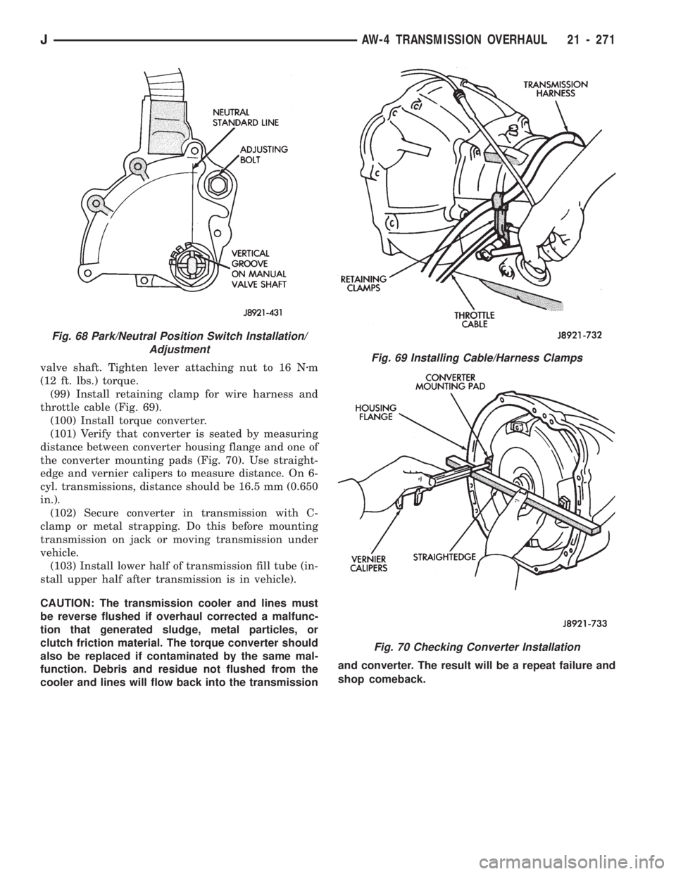
(101) Verify that converter is seated by measuring
distance between converter housing flange and one of
the converter mounting pads (Fig. 70). Use straight-
edge and vernier calipers to measure distance. On 6-
cyl. transmissions, distance should be 16.5 mm (0.650
in.).
(102) Secure converter in transmission with C-
clamp or metal strapping. Do this before mounting
transmission on jack or moving transmission under
vehicle.
(103) Install lower half of transmission fill tube (in-
stall upper half after transmission is in vehicle).
CAUTION: The transmission cooler and lines must
be reverse flushed if overhaul corrected a malfunc-
tion that generated sludge, metal particles, or
clutch friction material. The torque converter should
also be replaced if contaminated by the same mal-
function. Debris and residue not flushed from the
cooler and lines will flow back into the transmissionand converter. The result will be a repeat failure and
shop comeback.Fig. 69 Installing Cable/Harness Clamps
Fig. 70 Checking Converter Installation
Fig. 68 Park/Neutral Position Switch Installation/
Adjustment
JAW-4 TRANSMISSION OVERHAUL 21 - 271
Page 1412 of 1784
(29) Remove mode fork and mainshaft as assembly
(Fig. 22).
(30) Remove mode shift sleeve and mode fork as-
sembly from mainshaft (Fig. 23). Note position of
mode sleeve in fork and remove sleeve.(31) Remove intermediate clutch shaft snap ring
(Fig. 24).
(32) Remove clutch shaft thrust ring (Fig. 25).
Fig. 22 Removing Mode Fork And Mainshaft
Fig. 23 Removing Mode Fork And Sleeve
Fig. 24 Removing Intermediate Clutch Shaft Snap
Ring
Fig. 25 Removing Clutch Shaft Thrust Ring
JNP242 TRANSFER CASE 21 - 301
Page 1413 of 1784
(33) Remove intermediate clutch shaft (Fig. 26).
(34) Remove differential snap ring (Fig. 27).(35) Remove differential (Fig. 28).
(36) Remove differential needle bearings and both
needle bearing thrust washers from mainshaft.
(37) Slide low range fork pin out of shift sector slot
(Fig. 29)
Fig. 26 Removing Intermediate Clutch Shaft
Fig. 27 Removing Differential Snap Ring
Fig. 28 Differential Removal
Fig. 29 Disengage Low Range Fork
21 - 302 NP242 TRANSFER CASEJ
Page 1422 of 1784
(31) Install first mainshaft bearing spacer on
mainshaft (Fig. 61).
(32) Install bearing rollers on mainshaft (Fig. 61).
Coat bearing rollers with generous quantity of
petroleum jelly to hold them in place.
(33) Install remaining bearing spacer on mainshaft
(Fig. 61). Do not displace any bearings while installing
spacer.
(34) Install the differential (Fig. 62).Do not dis-
place the mainshaft bearings when installing
the differential.(35) Install the differential snap ring (Fig. 63).
(36) Install the intermediate clutch shaft (Fig. 64).
Fig. 61 Installing Mainshaft Bearing Rollers and
Spacers
Fig. 62 Differential Installation
Fig. 63 Installing Differential Snap Ring
Fig. 64 Installing Intermediate Clutch Shaft
JNP242 TRANSFER CASE 21 - 311
Page 1423 of 1784
(37) Install clutch shaft thrust washer (Fig. 65).
(38) Install clutch shaft snap ring (Fig. 66).
(39) Inspect mode fork assembly (Fig. 67). Replace
pads and bushing if necessary. Replace fork tube if
bushings inside tube are worn or damaged. Also
check springs and slider bracket (Fig. 67). Replace
worn, damaged components.(40) Install mode sleeve in mode fork (Fig. 68).
Then install assembled sleeve and fork on mainshaft.
Be sure mode sleeve splines are engaged in differen-
tial splines.
Fig. 65 Installing Clutch Shaft Thrust Washer
Fig. 66 Installing Clutch Shaft Snap Ring
Fig. 67 Inspect Mode Fork Assembly
Fig. 68 Installing Mode Fork And Sleeve
21 - 312 NP242 TRANSFER CASEJ
Page 1436 of 1784
AW-4 OIL PUMP WEAR LIMITS
AW-4 CLUTCH DISC AND PLATE THICKNESS
JTRANSMISSION/TRANSFER CASE SPECIFICATIONS 21 - 325